

Hotpoint Ariston CISKBH 6024 IX/1/HA Operating Instructions Manual
Operating Instructions
HOB
Contents
Installation, 2-3
Positioning
Electrical connection
Disposal
Description of the appliance, 4
Radiant zones
The control knobs
Extendable cooking zone control
Precautions and tips, 5
Practical advice on using the appliance
General safety
Care and maintenance, 6
Switching the appliance off
Cleaning the appliance
Disassembling the hob
GB
English,1
GB
CISKBH 6004 IX/1/HA
CISKBH 6024 DO IX/HA
CISKBH 6024 DO IX/1/HA
RS
Русский, 7
2
GB
Installation
Before operating your new appliance please read this
instruction booklet carefully. It contains important
information concerning the safe operation, installation
and maintenance of the appliance.
Please keep these operating instructions for future
reference. Pass them on to possible new owners of the
appliance.
Positioning
Keep all packaging materials out of the reach of children.
It may present a choking or suffocation hazard (see
Precautions and tips).
The appliance must be installed by a qualified
professional in accordance with the instructions provided.
Incorrect installation may damage property or cause harm
to people or animals.
Built-in appliance
Use the appropriate cabinet to ensure that the appliance
functions properly.
The supporting surface must be heat-resistant up to
a temperature of approximately 100°C.
If the appliance is to be installed above an oven, the
oven must have a forced ventilation cooling system.
Avoid installing the hob above a dishwasher: if this
cannot be avoided, place a waterproof separation
device between the two appliances.
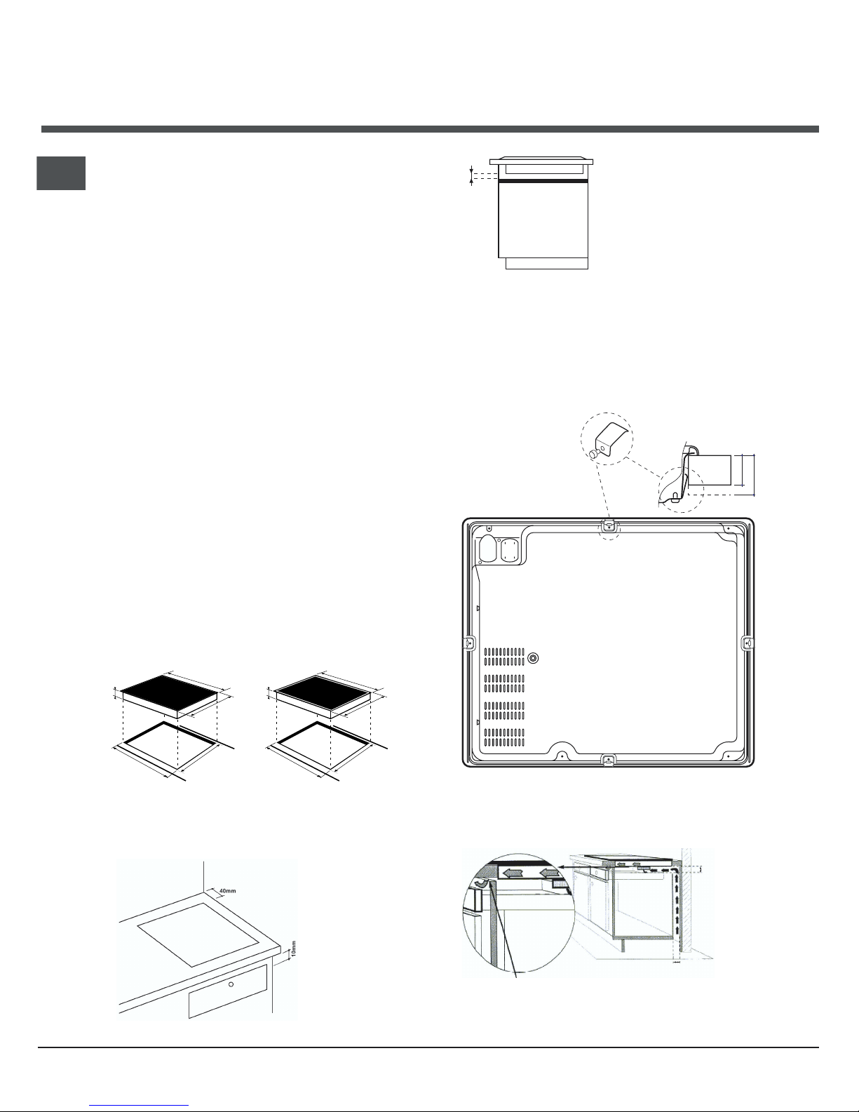
Depending on the hob you want to install, the
cabinet must have the following dimensions (see
figure):
Ventilation
To allow adequate ventilation and to avoid overheating
of the surrounding surfaces the hob should be positioned
as follows:
At a minimum of
40 mm from the
back panel and
600 mm from any
other vertical
surfaces.
So that a minimum
distance of 10 mm is
maintained between the
installation cavity and the
cabinet underneath.
Fixing
The appliance must be installed on a perfectly level
supporting surface.
Any deformities caused by improper fixing could change
the features and the operation of the hob.
560 +/- 1
490 +/- 1
48
590
520
560 +/- 1
490 +/- 1
48
574
504
10 mm
Distance to
keep between the
cut-out slot and
the cabinet
FRONT OF HOB
KITCHEN
WORKTOP
30
40
REAR SPRING ASSEMBLY
HOB FROM BELOW
40 mm min.
40mm
Opening of at least 5 mm
on the overall width
measurement of the surface.
Above an empty cabinet or a drawer
A space of at least 40 mm, or an opening of 5 mm on
the width measurement of the cabinet, should be created.
GB
3
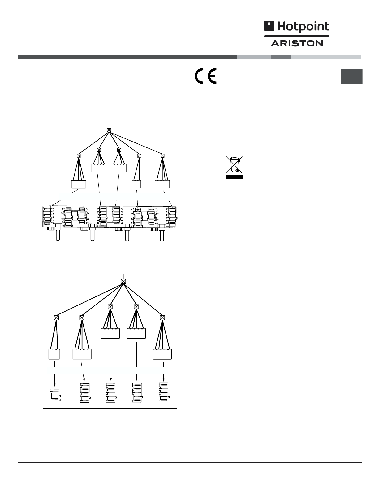
Connecting the hob to the oven
This appliance can only work if it has been connected to
a specific oven, listed on the sheet included in the
documents pouch.
CISKBH 6004/1/HA
CISKBH 6024 DO/HA-CISKBH 6024 DO/1/HA
This appliance conforms to the following
European Economic Community
directives:
- 73/23/EEC dated 19/02/73 (Low Voltage) and
subsequent amendments;
- 89/336/EEC dated 03/05/89 (Electromagnetic
Compatibility) and subsequent amendments;
- 93/68/EEC dated 22/07/93 and subsequent
amendments.
Disposal
When disposing of packaging material: observe
local legislation so that the packaging may be
reused.
The European Directive 2002/96/EC relating to Waste
Electrical and Electronic Equipment (WEEE) states
that household appliances should not be disposed of
using the normal solid urban waste cycle. Exhausted
appliances should be collected separately in order to
optimise the cost of re-using and recycling the
materials inside the machine, while preventing
potential damage to the atmosphere and to public
health. The crossed-out dustbin is marked on all
products to remind the owner of their obligations
regarding separated waste collection.
For further information relating to the correct disposal
of exhausted household appliances, owners may
contact the public service provided or their local
dealer.
BUILT-IN CERAMIC HOBS
OVEN
WHITE RED YELLOW BLUE GREEN
BUILT-IN CERAMIC HOBS
OVEN
WHITE RED YELLOWBLUE GREEN
4
GB
Description
of the appliance
Radiant zones
This type of burner consists of several coils that guarantee the even distribution of heat over the bottom of the
pan and ensure the success of all cooking on low heat: simmering, sauces or reheating.
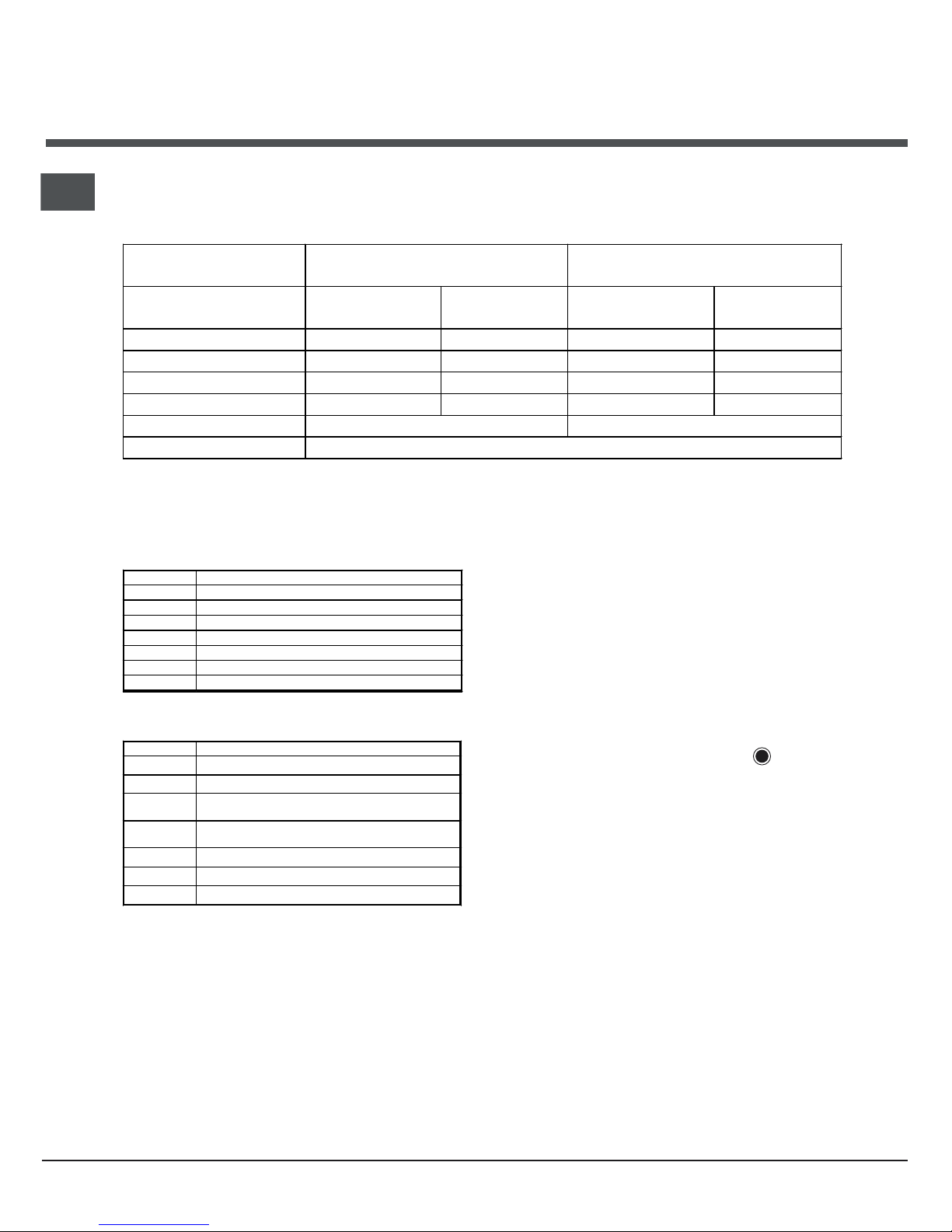
HOBS
CISKBH 6024 DO/HA
CISKBH 6024 DO/1/HA
CISKBH 6004/1/HA
Cooking zones
Power
(in W)
Diameter
(in mm)
Power
(in W)
Diameter
(in mm)
Back left
R 1200 140 R 2100 210
Front left
RD 1000/2200 210 R 1200 140
Back right
RO 1000/1800 180 R 1200 140
Front right
R 1400 160 R 1700 180
Overall power 6600 6400
R = simple radiant, RO = oval radiant, RD = dual radiant
The tables below feature information on how to use the zones to their full potential.
CISKBH 6024 DO/HA - CISKBH 6024 DO/1/HA
Power Type of dish
1 Melted butter or chocolate
2/3 Reheating liquids
4/5 Preparation of creams and sauces
6/7 Cooking stews, blanquette, desserts
8/9 Cooking pasta and rice
10/11 Sealing meat, fish, omelettes
12 Fried food
CISKBH 6004/1/HA
Power Type of dish
0 off
1 cooking greens, fish
2
steaming potatoes, cooking soups, chickpeas,
beans
3
steaming potatoes, cooking soups, chickpeas,
beans
4 for roasting (moderate)
5 for roasting (high)
6 for browning, to bring large volumes to the boil
As long as the temperature of the cooking zones
remains above 60°C, even after use, the residual
heat indicators stay on to prevent the risk of burns.
The control knobs
These are situated on the oven control panel and
allow for the continuous control of the power setting
of each cooking zone (from 1 to 12 or from 1 to 6).
Extendable cooking zone control
Extendable cooking zones (concentric or oval) are
indicated on the glass hob surface by a dual heating
zone.
To use the smaller zone only, set the control knob to
between 1 and 12 according to the desired heating
power.
To use the large zone, set the knob to
and then
adjust it to the desired heating power.
 Loading...