

Page 1
XBC 901 GH TC
XBM 181 GH TC S
XBM 181 GH TC D
XBM 211 GH TC S
XBM 21 1 GH TC D
Piano di cottura
Istruzioni per l'installazione e l'uso 1
Hob
Instructions for installation and use 8
CH
Plan de cuisson
Instruction pour l'installation et l'emploi 15
CH
Kochplatte
Informationen für installation un gebrauch 22
kookplaat
Gebruiksaanwijzingen voor de plaatsing en gebruik 29
Planos de cocción
Instrucciones para la instalación y uso 36
Planos de cozedura
Instruções para a instalação e o uso 43
Page 2

Complimenti!
Avete acquistato un elettrodomestico costruito con tecnologie avanzate e materiali di qualità. Utilizzandolo avrete modo di
apprezzarne la funzionalità e la sicurezza, caratteristiche costanti della nostra produzione.
INDICE
Avvertenze................................................................................................................…………………................... pag. 1
Descrizione del piano di cottura..................................………………………..........………………………............…......“ 2
Istruzioni per l’uso - Bruciatori gas............................…………………………………………………....................…......“ 3
Pulizia e manutenzione................................................................……………………………………............................“ 3-4
Istruzioni per l’installatore..................................................…………..………………………......................….........…..“ 4
Posizionamento.........................................................................................................................................................“ 4
Installazione dei piani di cottura..........................................................……………………………………….................“ 5
Collegamento alimentazione gas........................................................……………………………………….................“ 6
Adattamento ai diversi tipi di gas..........................................................…………………………………………............“ 6
Regolazione minimi..............................................................................………………………………..…………..........“ 6
Collegamento elettrico..........................................................................…………………………………………............“ 6-7
Caratteristiche dei bruciatori ed ugelli.............................................…………………………………………..................“ 7
QUESTE ISTRUZIONI SONO V ALIDE SOLO PER I PAESI DI DESTINAZIONE I CUI SIMBOLI FIGURANO SUL LIBRETTO
E SULLA TARGA MATRICOLA DELL’APPARECCHIO.
A VVERTENZE
1. Questo apparecchio è stato concepito per essere
utilizzato da privati per un uso di tipo non
professionale all’interno di abitazione comune.
2. Leggere attentamente le avvertenze contenute nel
presente libretto istruzioni, in quanto forniscono
importanti indicazioni riguardanti la sicurezza di
installazione, d’uso e di manutenzione. Conservare
con cura questo libretto per ogni eventuale
consultazione.
3. Dopo aver tolto l’imballaggio assicurarsi dell’integrità
dell’apparecchio. In caso di dubbio non utilizzare
l’apparecchio e rivolgersi a personale professionalmente
qualificato.
4. Non lasciare l’apparecchio inutilmente inserito. Spegnere
l’interruttore generale dell’apparecchio quando lo stesso
non è utilizzato e chiudere il rubinetto del gas.
5. È necessario che tutte le operazioni relative
all’installazione e alla regolazione vengano eseguite da
personale qualificato, secondo le norme in vigore. Le
istruzioni specifiche sono descritte nella sezione riservata
all’installatore.
6. Verificare periodicamente il buono stato del tubo di
collegamento gas e farlo sostituire da personale qualificato
non appena presenta qualche anomalia.
7. Il cavo di alimentazione ed il tubo di collegamento gas di
questo apparecchio non devono essere sostituiti
dall’utente. In caso di danneggiamento e di eventuale
sostituzione rivolgersi esclusivamente ad un centro di
assistenza tecnica autorizzato.
8. Prima di collegare l’apparecchio accertarsi che i dati sulla
targhetta caratteristiche (su parte inferiore
dell’apparecchio e su ultima pagina libretto) siano
rispondenti a quelli della rete di distribuzione elettrica e
gas.
9. Verificare che la portata elettrica dell’impianto e delle
prese di corrente siano adeguate alla potenza massima
dell’apparecchio indicata sulla targhetta. In caso di
dubbio rivolgersi ad una persona professionalmente
qualificata.
10. I bruciatori e le griglie rimangono caldi per lungo tempo
dopo l’uso. Fare attenzione a non toccarli.
1 1. Sui bruciatori non devono essere poste pentole instabili
o deformate onde evitare incidenti per rovesciamento.
12. Non utilizzare liquidi infiammabili in vicinanza
dell’apparecchio quando è in uso.
1
Page 3
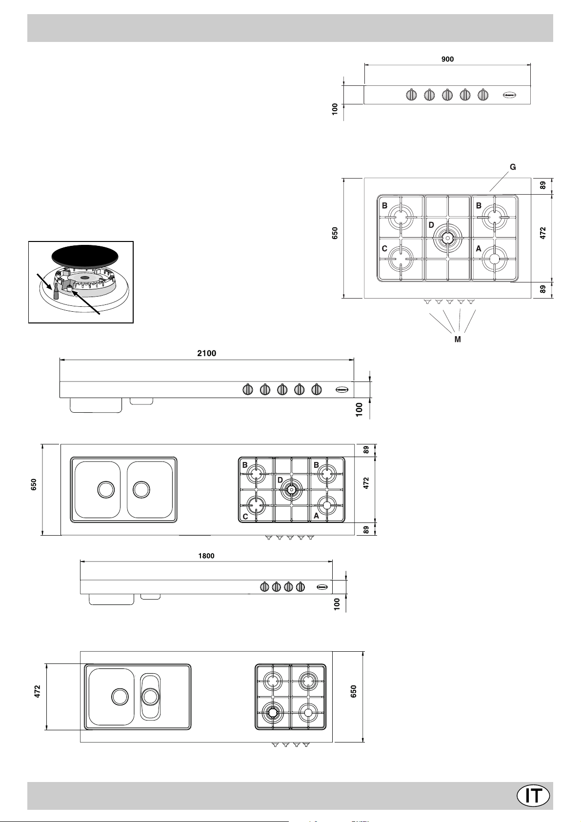
DESCRIZIONE DEI PIANI DI COTTURA
A Bruciatore gas Ausiliario
B Bruciatore gas Semirapido
C Bruciatore gas Rapido
D Bruciatore gas Tripla Corona
G Griglie di appoggio per recipienti di cottura
M Manopole di comando dei bruciatori gas
F Dispositivo di sicurezza (presente solo su al-
cuni modelli) - Interviene in caso di spegnimento accidentale della fiamma (trabocco di liquidi,
correnti d'aria, ...) bloccando l'erogazione del gas
al bruciatore.
E Candela di accensione dei bruciatori gas
F
E
XBC 901 GH TC
XBM 211 GH TC
* disponibile anche in versione sx (zona cottura a sinistra)
XBM 181 GH TC
2
Page 4
ISTRUZIONI PER L'USO
Bruciatori gas
Sono di diverse dimensioni e potenze. Scegliete quello più
adatto al diametro del recipiente da utilizzare.
Il bruciatore prescelto può essere regolato dalla manopola
"M" corrispondente come segue:
Rubinetto chiuso
Apertura massima
Apertura minima
Nelle vicinanze delle manopole i simboli ( ) indicano la
posizione sul piano del bruciatore relativo.
Inoltre, nelle vicinanze delle manopole i simboli indicano la
posizione sul piano del bruciatore relativo.
I bruciatori sono dotati di sicurezza contro fughe di gas a
termocoppia. Questo dispositivo provvede a bloccare l’uscita
del gas nel caso che la fiamma del bruciatore si spenga
durante il funzionamento.
Per accendere uno dei bruciatori procedere come segue:
• ruotare la manopola corrispondente in senso antiorario
fino al simbolo della fiamma grande;
• premere la manopola a fondo per azionare l’accensione
automatica del gas;
• mantenere la manopola premuta per circa 10 secondi con
la fiamma accesa per consentire il riscaldamento della
termocoppia di sicurezza;
• rilasciare la manopola, verificando che l’accensione sia
avvenuta in modo stabile. In caso contrario, ripetere
l’operazione.
Per avere la potenza minima ruotare la manopola verso il
simbolo della fiamma piccola. Sono possibili regolazioni
intermedie, posizionando la manopola tra il simbolo di
fiamma grande e quello della fiamma piccola.
Per spegnere il bruciatore ruotare la manopola in senso
orario fino alla posizione di chiuso " " .
Importante:
• Non azionare il dispositivo di accensione automatica per
più di 15 secondi consecutivi.
• In alcuni casi la difficoltà di accensione è dovuta ad
eventuale aria che può trovarsi all’interno del condotto
del gas.
• Nel caso di uno spegnimento accidentale della fiamma dei
bruciatori, il gas continua ad uscire per qualche istante
prima che intervenga il dispositivo di sicurezza. Chiudere
la manopola di comando e non ritentare l’accensione per
almeno 1 minuto, lasciando così dileguare il gas uscito
che può essere pericoloso.
• Quando l’apparecchiatura non è in funzione controllare che
le manopole siano in posizione di chiuso " ". Si consiglia
inoltre di chiudere il rubinetto principale del condotto di
alimentazione del gas.
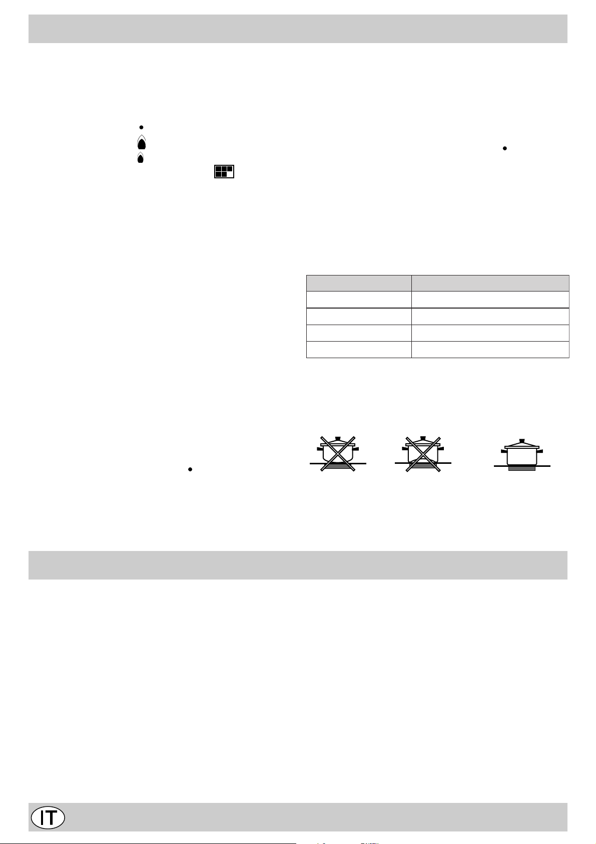
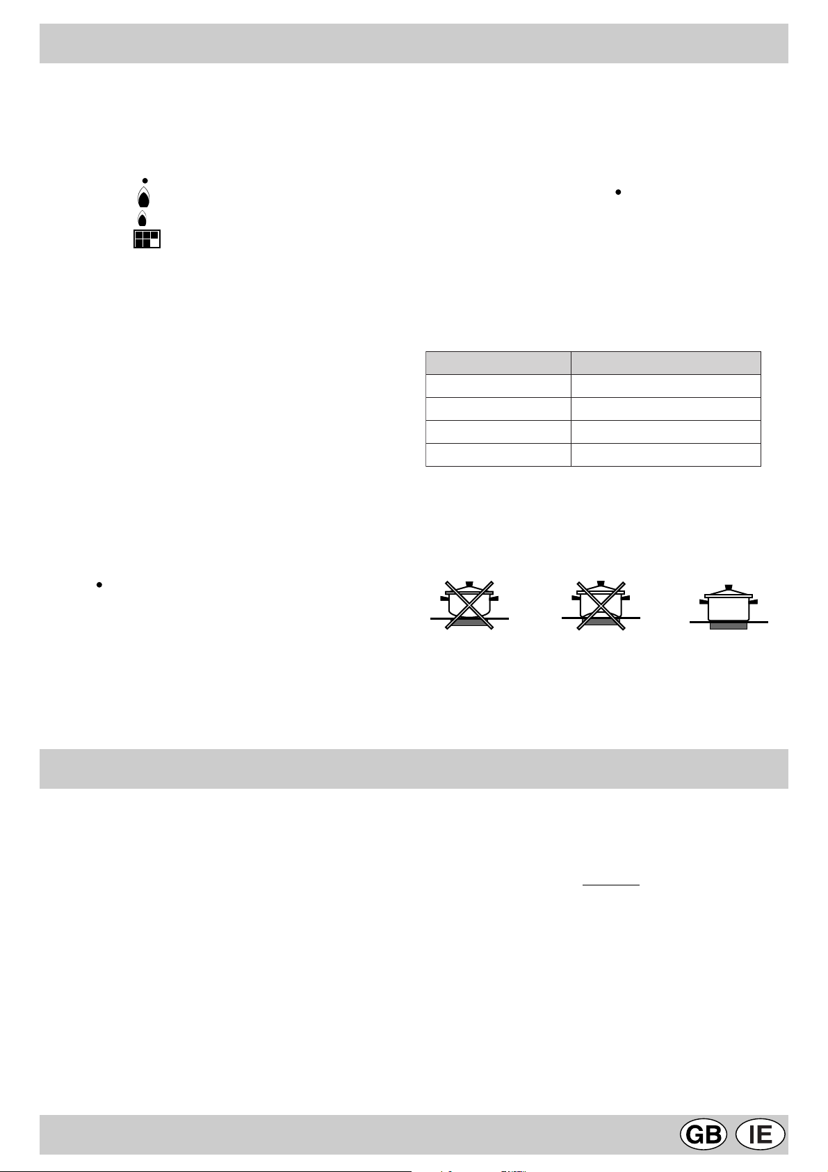
Uso dei bruciatori
Per ottenere dai bruciatori il massimo rendimento si consiglia
adoperare solo pentole di diametro adatto al bruciatore
utilizzato, evitando che la fiamma fuoriesca dal fondo della
pentola (vedi tabella seguente).
Inoltre, quando un liquido inizia a bollire, si consiglia di ridurre
la fiamma quanto basta per mantenere l’ebollizione.
erotaicurB .mcnialotnepalledortemaiD
.A oirailisuA
.B odiparimeS
.C odipaR
.D anoroCalpirT
Al fine di ottenere il massimo rendimento è utile ricordare
quanto segue:
Sui bruciatori possono essere utilizzati tutti i tipi di casseruole. L’importante è che il fondo sia perfettamente piano.
41a6ad
02a51ad
62a12ad
62a42ad
PULIZIA E MANUTENZIONE
Per una lunga durata dell’apparecchiatura è indispensabile
eseguire frequentemente una accurata pulizia generale,
tenendo conto che:
• L’apparecchiatura deve essere disinserita
elettricamente prima di iniziare la pulizia.
• Evitare di effettuare pulizie sulle parti ancora calde
dell’apparecchiatura.
• Le parti smaltate, cromate ed in vetro, vanno lavate con
acqua tiepida senza usare polveri abrasive e sostanze
corrosive che potrebbero rovinarle.
• Le parti in acciaio e soprattutto le zone con i simboli
serigrafati non devono essere pulite con diluenti o detersivi
abrasivi; utilizzare preferibilmente solo un panno morbido
inumidito con acqua tiepida e detersivo liquido per piatti
(passare il panno eseguendo il movimento nello stesso
senso della satinatura dell'acciaio).
Per lo sporco difficile è consentito l'uso di alcool denaturato.
L'acciaio inox può rimanere macchiato se rimane a contatto per lungo tempo con acqua fortemente calcarea o
con detergenti aggressivi (contenenti fosforo). Si consiglia quindi di sciacquare sempre abbondantemente e di
asciugare accuratamente con una pelle di daino.
• Dopo la pulizia è possibile eseguire eventuali trattamenti
per risaltare la lucentezza dell' acciaio e prevenire eventuali
ingiallimenti; a tal proposito si consiglia l'utilizzo
dell'apposita "crema specifica per la cura dell'acciaio" in
dotazione e richiedibile presso i nostri Centri Assistenza.
• Evitare di lasciare sulle parti smaltate o verniciate dei liquidi
acidi (aceto, succo di limone, detergenti aggressivi, ecc.)
• Gli elementi mobili dei bruciatori del piano di cottura
3
Page 5
vanno lavati frequentemente con acqua calda e detersivo
avendo cura di eliminare le eventuali incrostazioni.
Controllare che le fessure di uscita del gas non siano
otturate. Asciugarli accuratamente prima di riutilizzarli.
• Eseguire frequentemente la pulizia della parte terminale
delle candelette di accensione automatica del piano di
cottura.
ISTRUZIONI PER L'INSTALLATORE
Ingrassaggio dei rubinetti
Con il tempo può verificarsi il caso di un rubinetto che si
blocchi o presenti difficoltà nella rotazione, pertanto sarà necessario provvedere alla pulizia interna e alla sostituzione
del grasso. Questa operazione deve essere effettuata da
un tecnico autorizzato dal costruttore.
Le istruzioni che seguono sono rivolte all’installatore
qualificato affinché compia le operazioni di installazione,
regolazione e manutenzione tecnica nel modo più corretto e
secondo le norme in vigore.
Importante: qualsiasi intervento di regolazione,
manutenzione, ecc. deve essere eseguito con il piano
elettricamente disinserito. Qualora sia necessario
mantenerlo collegato elettricamente, si dovranno prendere
le massime precauzioni.
I piani di cottura hanno le seguenti caratteristiche tecniche:
-Categoria II 2H3+ -Classe 1
Posizionamento
Questa apparecchiatura può essere installata e funzionare
solo in locali permanentemente ventilati secondo le
prescrizioni delle Norme UNI-CIG 7129 e 7131 in vigore.
Devono essere osservati i seguenti requisiti:
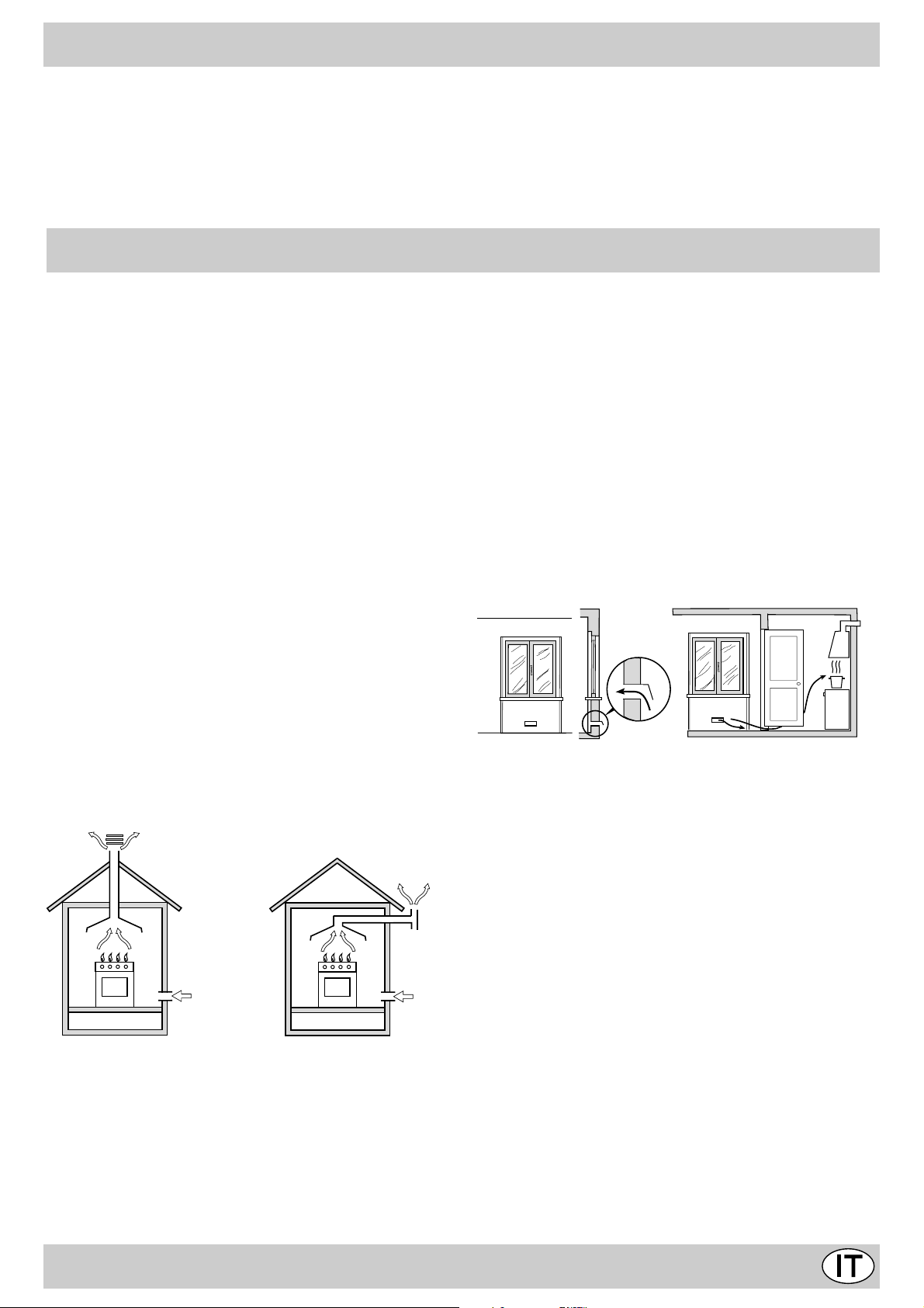
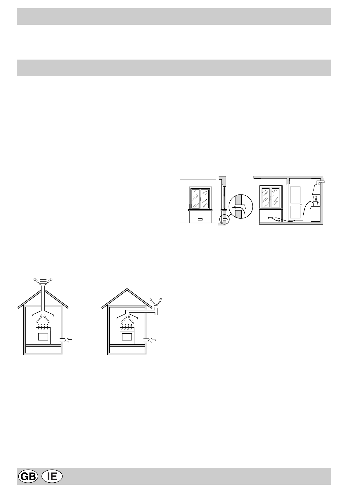
• L’apparecchio deve scaricare i prodotti della combustione
in una apposita cappa, che deve essere collegata ad un
camino, canna fumaria o direttamente all’esterno (fig.1).
• Se non è possibile l’applicazione di una cappa, è permesso
l’uso di un elettroventilatore, installato su finestra o su
parete affacciate all’esterno, da mettere in funzione
contemporaneamente all’apparecchio.
fig.1
ventilazione singoli o collettivi ramificati conformi alla norma
UNI-CIG 7129. L’aria deve essere prelevata direttamente
dall’esterno, lontana da fonti di inquinamento. L’apertura di
aerazione dovrà avere le seguenti caratteristiche (fig.2A):
• avere una sezione libera totale netta di passaggio di almeno
6 cm² per ogni kW di portata termica nominale
dell’apparecchio, con un minimo di 100 cm² (la portata
termica è rilevabile nella targhetta segnaletica);
• essere realizzata in modo che le bocche di apertura, sia
all’interno che all’esterno della parete, non possano venire
ostruite;
• essere protette ad esempio con griglie, reti metalliche, ecc.
in modo da non ridurre la sezione utile suindicata;
• essere situate ad una altezza prossima al livello del
pavimento.
Particolare A Locale Locale da
adiacente ventilare
A
Esempi di aperture di ventilazione Maggiorazione della fessura fra
per l’aria comburente porta e pavimento
fig. 2A fig. 2B
L’afflusso dell’aria può essere ottenuto anche da un locale
adiacente purché questo locale non sia una camera da letto
o un ambiente con pericolo di incendio quali rimesse, garage,
magazzini di materiale combustibile, ecc., e che sia ventilato
in conformità alla norma UNI-CIG 7129.
In camino o in canna fumaria ramificata Direttamente all’esterno
(riservata agli apparecchi di cottura)
Ventilazione ambiente cucina
É necessario che nell’ambiente dove viene installato
l’apparecchio possa affluire una quantità di aria pari a quanta
ne viene richiesta dalla regolare combustione del gas e dalla
ventilazione dell’ambiente. L’afflusso naturale dell’aria deve
avvenire attraverso aperture permanenti praticate su pareti
del locale che danno verso l’esterno, oppure da condotti di
Il flusso dell’aria dal locale adiacente a quello da ventilare
deve avvenire liberamente attraverso aperture permanenti,
di sezione non minore di quella suindicata. Tali aperture
potranno anche essere ricavate maggiorando la fessura tra
porta e pavimento (fig.2B). Se per l’evacuazione dei prodotti
della combustione viene usato un elettroventilatore, l’apertura
di ventilazione dovrà essere aumentata in funzione della
massima portata d’aria dello stesso. L’elettroventilatore dovrà
avere una portata sufficiente a garantire un ricambio orario
di aria pari a 3÷5 volte il volume del locale. Un utilizzo
intensivo e prolungato dell’apparecchio può necessitare di
un’aerazione supplementare, per esempio l’apertura di una
finestra o un’aerazione più efficace aumentando la potenza
di aspirazione dell’elettroventilatore se esso esiste. Gli
apparecchi sprovvisti di dispositivo di sicurezza per assenza
di fiamma possono essere utilizzati solo in ambienti con
ventilazione maggiorata con una sezione minima di apertura
di aerazione 200 cm² (D.M. 21-04-94).
4
Page 6
I gas di petrolio liquefatti, più pesanti dell’aria, ristagnano
verso il basso. Quindi i locali contenenti bombole di GPL
devono avere delle aperture verso l’esterno al livello del
pavimento, così da permettere l’evacuazione dal basso delle
eventuali fughe di gas. Inoltre non depositare bombole di
GPL (anche vuote) in locali a livello più basso del suolo; è
opportuno tenere nel locale solo la bombola in utilizzo,
collegata lontana da sorgenti di calore che possano portarla
ad una temperatura superiore a 50 °C.
Installazione dei piani di cottura
È necessario prendere le opportune precauzioni al fine di
assicurare una installazione rispondente alle norme
antinfortunistiche in vigore (CEI-UNI-CIG) per l’allacciamento
elettrico e gas.
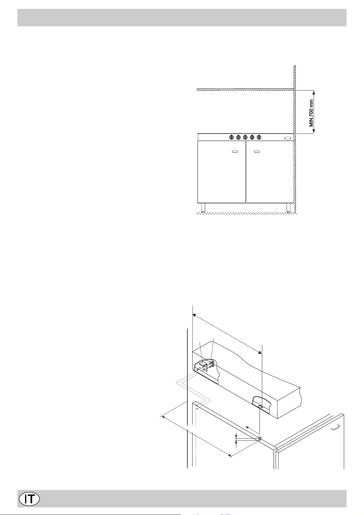
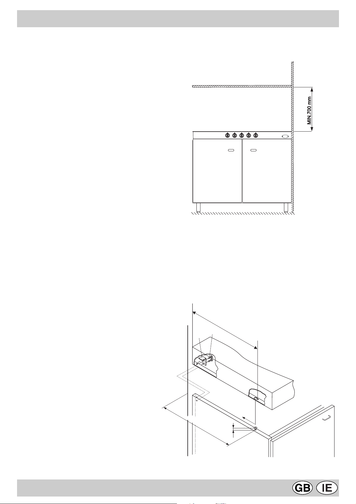
Per il buon funzionamento dei piani di cottura da appoggio
installati nei mobili devono essere rispettate le distanze
minime indicate in fig.3. Inoltre, le superfici adiacenti e la
parete posteriore devono essere idonee per resistere ad una
sovratemperatura di 65°C.
Fissaggio al mobile
Per il fissaggio dei piani eseguire le seguenti operazioni
(fig. 4);
• avvitare al mobile 2 viti "A" (in dotazione) con le distanze
dalla parete posteriore indicate in figura, lasciando le teste
delle viti sporgenti 1,5 mm dal legno;
• agganciare il piano alle 2 viti "A" e spingerlo all'indietro;
• fissarlo al mobile nella parte posteriore usando le 2
squadrette "B" e le quattro viti "C" in dotazione.
fig.3
XmmX
mm
C
B
XmmX
mm
mm
1.5 mm1.5
5
A
fig.4
Page 7
Collegamento alimentazione gas
• Il collegamento dell’apparecchio alla tubazione o alla
bombola del gas deve essere effettuato secondo le
prescrizioni delle norme in vigore (UNI-CIG 7129 e 7131)
solo dopo essersi accertati che l’apparecchiatura è regolata
per il tipo di gas con cui sarà alimentata.
• Questo apparecchio è predisposto per funzionare con il
gas indicato nell’etichetta posta sul piano stesso. Nel caso
che il gas distribuito non corrisponda a quello per cui
l’apparecchio è predisposto, procedere alla sostituzione
degli ugelli corrispondenti (in dotazione), consultando il
paragrafo “Adattamento ai diversi tipi di gas”.
• Per un sicuro funzionamento, per un adeguato uso
dell’energia e maggiore durata dell’apparecchiatura,
assicurarsi che la pressione di alimentazione rispetti i valori
indicati nella tabella 1 “Caratteristiche dei bruciatori ed
ugelli”, altrimenti installare sulla tubazione di ingresso un
apposito regolatore di pressione secondo la norma UNICIG 7430.
• Effettuare Il collegamento in modo da non provocare
sollecitazioni di nessun genere sull’apparecchio.
Collegare al raccordo orientabile (filettato ½"G maschio),
posto nel lato posteriore destro dell’apparecchio (fig.5), per
mezzo di tubo metallico rigido e a raccordi conformi alla
norma UNI-CIG 7129, oppure con tubo flessibile metallico a
parete continua conforme alla norma UNI-CIG 9891, la cui
massima estensione non deve superare i 2000 mm.
• rimontare le parti eseguendo all’inverso le operazioni.
• al termine dell’operazione, sostituite la vecchia etichetta
taratura con quella corrispondente al nuovo gas d’utilizzo,
reperibile presso i Nostri Centri Assistenza Tecnica.
A
fig.6
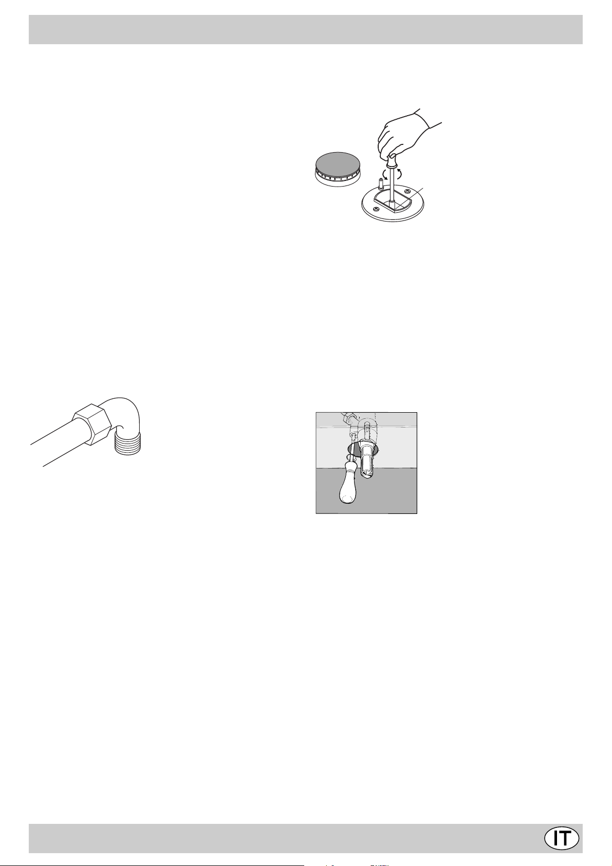
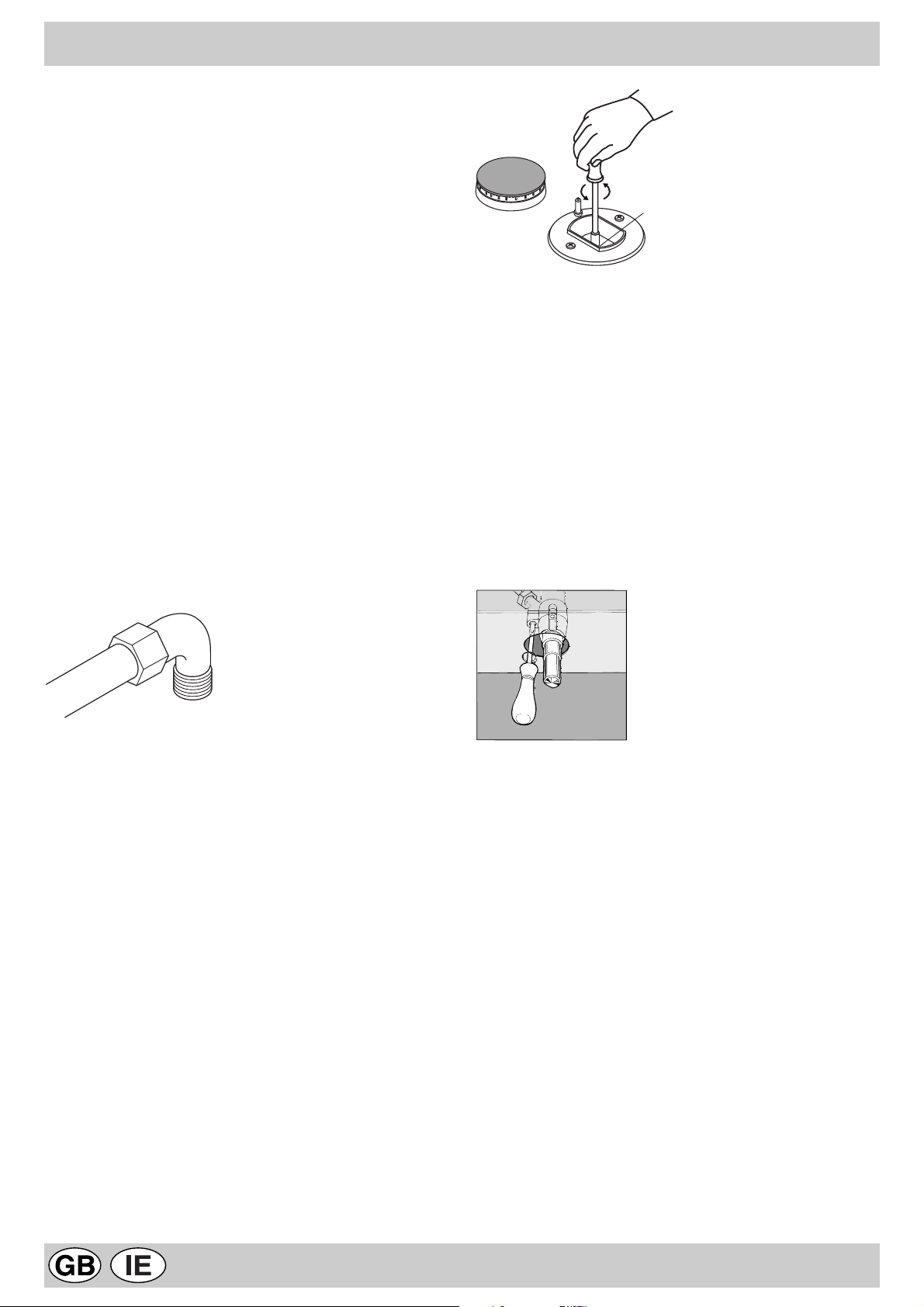
Regolazione minimi
• Con il bruciatore acceso, portare il rubinetto sulla posizione di minimo;
• togliere la manopola (fig.7) ed agire con un cacciavite sulla vite di regolazione posta all’interno o di fianco all’astina
del rubinetto fino ad ottenere una piccola fiamma regolare
(svitando la vite il minimo aumenta, avvitandola diminuisce).
N.B.: nel caso dei gas liquidi, la vite di regolazione dovrà
essere avvitata a fondo.
• verificare che ruotando rapidamente la manopola dalla posizione di massimo a quella di minimo non si abbiano
spegnimenti dei bruciatori.
fig.5
Nel caso sia necessario ruotare il raccordo, sostituire
tassativamente la guarnizione di tenuta (in dotazione con
l’apparecchio).
Ad installazione ultimata accertarsi che la tenuta del circuito
gas, delle connessioni interne e dei rubinetti sia perfetta
impiegando una soluzione saponosa (mai una fiamma).
Verificare inoltre che il tubo di collegamento non possa venire
a contatto con parti mobili in grado di danneggiarlo o
schiacciarlo.
Accertarsi che la conduttura del gas naturale sia sufficiente
per alimentare l’apparecchio quando tutti i bruciatori sono in
funzione.
Importante: Per effettuare l’allacciamento con gas liquido
(in bombola), interporre un regolatore di pressione conforme
alla norma UNI-CIG 7432-75.
Adattamento ai diversi tipi di gas
Per adattare il piano ad un tipo di gas diverso da quello per
il quale esso è predisposto (indicato sulla etichetta fissata
nella parte superiore del piano o sull'imballo), occorre sostituire gli ugelli dei bruciatori effettuando le seguenti operazioni:
• togliere le griglie del piano e sfilare i bruciatori dalle loro
sedi;
• svitare gli ugelli (fig.6), servendosi di una chiave a tubo da
7 mm. e sostituirli con quelli adatti al nuovo tipo di gas
(vedi tabella 1 “Caratteristiche dei bruciatori ed ugelli”).
fig.7
Collegamento elettrico
È OBBLIGATORIO IL COLLEGAMENTO A TERRA
DELL’APPARECCHIATURA.
I piani sono predisposti per il funzionamento con corrente
alternata alla tensione e frequenza di alimentazione indicate
sulla targhetta caratteristiche (posta sotto il piano o alla fine
del libretto istruzioni). Accertarsi che il valore locale della
tensione di alimentazione sia lo stesso di quello indicato sulla
targhetta.
Allacciamento del cavo alimentazione elettrico alla rete
Per i modelli privi di spina, montare sul cavo una spina
normalizzata per il carico indicato sulla targhetta
caratteristiche e collegarla ad una adeguata presa di
corrente.
Desiderando un collegamento diretto alla rete è necessario
interporre tra l’apparecchio e la rete un interruttore onnipolare
con apertura minima tra i contatti di 3 mm, dimensionato al
carico e rispondente alle norme in vigore.
6
Page 8
Il filo di terra giallo-verde non deve essere interrotto
dall’interruttore.
Il cavo di alimentazione deve essere posizionato in modo
che non raggiunga in nessun punto una temperatura
superiore di 50 °C a quella ambiente.
Nel caso di installazione sopra un forno da incasso
l’allacciamento elettrico del piano e quello del forno devono
essere realizzati separatamente, sia per ragioni di sicurezza
elettrica, sia per facilitare l’eventuale estraibilità del forno.
Non utilizzare riduzioni, adattatori o derivatori in quanto essi
potrebbero provocare riscaldamenti o bruciature.
Prima di effettuare l’allacciamento accertarsi che:
• la valvola limitatrice e l’impianto domestico possano
sopportare il carico dell’apparecchiatura (vedi targhetta
caratteristiche);
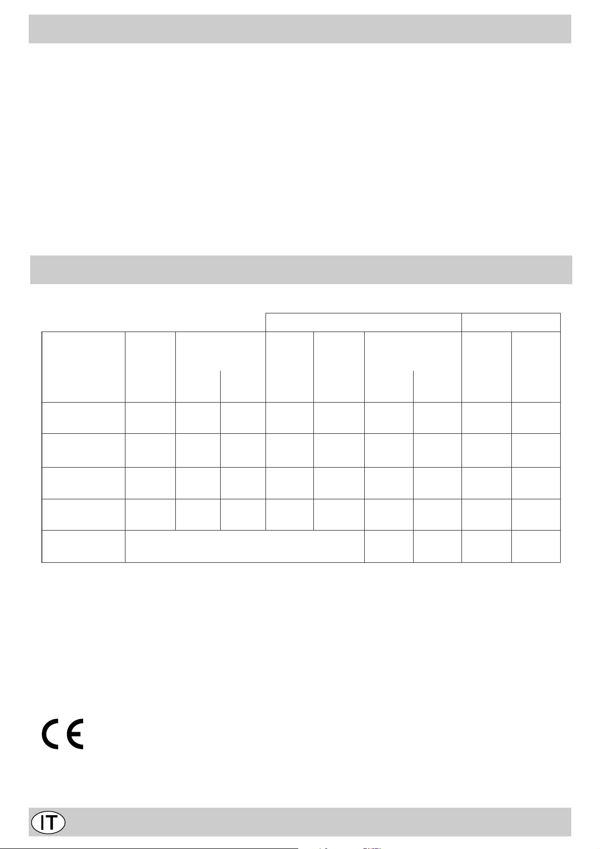
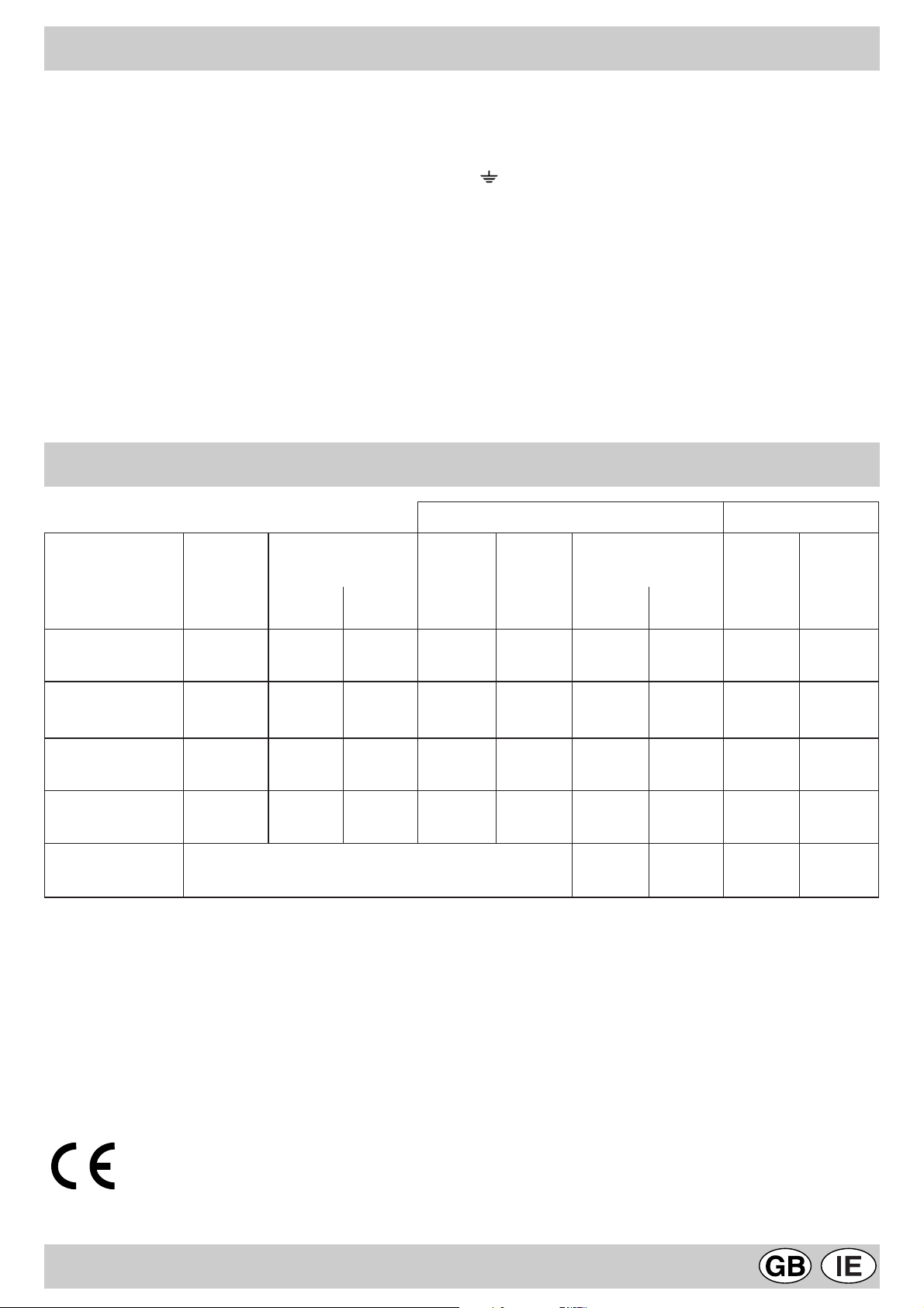
CARATTERISTICHE DEI BRUCIATORI ED UGELLI
1allebaTodiuqilsaGelarutansaG
• l’impianto di alimentazione sia munito di efficace
collegamento a terra secondo le norme e le disposizioni di
legge in vigore;
• la presa o l’interruttore onnipolare siano facilmente
raggiungibili con il piano installato.
DECLINIAMO OGNI RESPONSABILITÀ NEL CASO LE
NORME ANTINFORTUNISTICHE NON VENGANO
RISPETTATE.
Sostituzione del cavo
Utilizzare un cavo in gomma del tipo H05RR-F con una
sezione 3 x 0.75 mm²
Il conduttore giallo-verde dovrà essere più lungo di 2÷3 cm.
degli altri conduttori.
erotaicurBortemaiD
)mm(
.nimoN.todiR03G13G02G
acimretaznetoP
)*.s.H(Wk
ssap-yB
001/1
)mm(
ollegU
001/1
)mm(
*atatroP
h/g
ollegU
001/1
)mm(
*atatroP
h/l
CodipaR00100.37.00468812412611682
BodiparimeS5756.14.0034602181169751
AoirailisuA5500.13.0720537171759
DanorocalpirT03152.33.17519632232421903
idenoisserP
enoizatnemila
037302
* A 15°C e 1013 mbar-gas secco
Propano G31 H.s. = 50,37 MJ/kg
Butano G30 H.s. = 49,47 MJ/kg
Metano G20 H.s. = 37,78 MJ/m
Questa apparecchiatura è conforme alle seguenti
Direttive Comunitarie:
3
- 73/23/CEE del 19/02/73 (Bassa Tensione) e successive
modificazioni;
- 89/336/CEE del 03/05/89 (Compatibilità Elettromagnetica) e successive modificazioni;
- 90/396/CEE del 29/06/90 (Gas) e successive
modificazioni;
- 93/68/CEE del 22/07/93 e successive modificazioni.
7
Page 9

Congratulations!
You have just purchased an electrical household appliance that has been made using advanced technology and quality
materials. As time passes, you will appreciate its practicality and safety, which are constant features of our production.
CONTENTS
Recommendations.........................................................................................................................................page 8
Hob description.............................................................…………………....………………..............….................." 9
Instructions for use - gas burners...........................…………………...……………..…........................................." 10
Cleaning and maintenance...........................................................…….......………………………........................." 10-1 1
Instructions for the installer.............................................…………..………………………..................................... "11
Position..................................................................................…………………………………………....................."11
Hobs installation..................................................................................…………………………………………........" 12
Gas supply connection........................................................................…………………………………………........" 13
Adaptation to a different type of gas.....................................................………………………………..………........." 13
Electrical connection.............................................................................……………………………………….........." 13-14
Burners and nozzles specifications.................................................………………………………………................" 14
THESE INSTRUCTIONS ARE ONL Y V ALID FOR THE COUNTRIES OF DESTINA TION WHOSE SYMBOLS ARE SHOWN
IN THE BOOKLET AND ON THE APPLIANCE RATING PLATE.
RECOMMENDA TIONS
1. This appliance has been designed for private, non-
professional use in normal dwellings.
2. Carefully read the recommendations in this
instruction booklet, as they give important advice
regarding safe installation, use and maintenance.
Keep this booklet in a safe place for further reference
when required.
3. After removing the packaging, check that the appliance
is intact. If in doubt, do not use the appliance and contact
professionally qualified personnel.
4. All installation and adjustment operations should be
carried out by qualified engineers in accordance with
current regulations. Specific directions are given in the
“installation instructions” paragraph.
5. Periodically check the condition of the gas connection
pipe and have it replaced by a qualified technician as
soon as it shows any signs of wear or anomaly.
6. Under no circumstances should the user replace the
power supply cable or the gas connection pipe of this
appliance. In the event of damage or the necessity for
replacement, only contact an authorised service centre.
7. Before connecting the appliance, make sure that the data
on the rating plate (situated on the bottom part of the
appliance and on the last page of the booklet) correspond
to those of the mains electricity and gas supplies.
8. Check that the capacity of the electrical system and the
power outlets are suitable for the maximum power of
the appliance, indicated on the rating plate. If in doubt,
consult a professionally qualified technician.
9. Do not leave the appliance plugged in if it is not in use.
Switch off the main switch and gas supply when you are
not using the hob.
10. The gas burners and pan supports remain heated for a
long time after use. Take care not to touch them.
11. To avoid accidental spillage do not use cookware with
uneven or deformed bottoms on the burner.
12. Never use flammable liquids such as alcohol or gasoline,
etc. near the appliance when it is in use.
8
Page 10
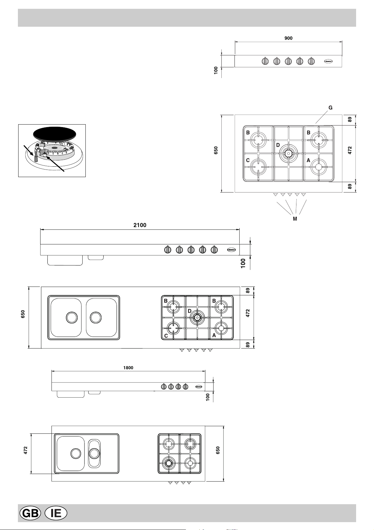
HOB DESCRIPTION
A Auxiliary gas burner
B Semi-rapid gas burner
C Rapid gas-burner
D Triple ring gas burner
G Pan supports
M Control knobs for gas burners
E Ignitor for gas burners
F Safety device - Activates if the flame accidentally goes
out (spills, drafts, etc.), interrupting the delivery of gas to
the burner.
F
E
XBC 901 GH TC
* Also available in the left-hand version (cooking zone on the left).
XBM 211 GH TC
XBM 181 GH TC
9
Page 11
INSTRUCTIONS FOR USE
Gas burners
The burners differ in size and power. Choose the most
appropriate one for the diameter of the cookware being used.
The burner can be regulated with the corresponding control
knob "M" by using one of the following settings:
Off
High flame
Low flame
The symbols ( ) near the knobs show the position of
the relative burner on the hob.
The symbols near the knobs show the position of the relative
burner on the hob. The burners are fitted with automatic
ignition and thermocouple safety device, which automatically
cuts off the gas from the burner in a few seconds if the flame
accidentally goes out during operation.
To ignite a burner proceed as follows:
• turn the relative knob counter-clockwise until the pointer is
on the high-flame symbol;
• press the knob down fully to activate the automatic gas
ignition;
• keep the knob pressed down for about 10 seconds with
the flame lit to allow the safety thermocouple to be heated;
• release the knob, checking that the flame is stable. If it is
not, repeat the operation.
For minimum power, turn the knob towards the low flame
symbol. Intermediate positions are possible by putting the
knob anywhere between the high and the low flame symbol.
To turn off the burner, turn the knob clockwise to the off
position " " .
Important:
• Do not activate the automatic ignition device for more than
15 consecutive seconds.
• Difficulty in ignition is sometimes due to air inside the gas
duct.
• If a burner flame accidentally goes out, the gas continues
to exit for a few moments before the safety device activates.
Turn the control knob to the off position and do not attempt
ignition again for at least 1 minute, thereby letting the gas
disperse, which could otherwise be a danger.
• When the equipment is not in operation, check that the
knobs are in the off position " ". The main gas supply cutoff cock should also be closed.
Using the burners
T o obtain maximum efficiency from the burners, it is advisable
to use only pans with a diameter that is suitable for the burner
being used, so that the flame does not extend beyond the
pan base (see following table).
When a liquid starts boiling, it is advisable to turn the flame
down just enough to keep the liquid simmering.
renruB .mcninapehtforetemaiD
.A yrailixuA
.B dipar-imeS
.C dipaR
.D gnirelpirT
To obtain the best results with the cooktop, several
fundamental rules should be followed while cooking or
preparing food.
• Use cookware with a flat bottom to make certain that the
pot sets properly on the cooking area.
41ot6morf
02ot51morf
03ot12morf
03ot42morf
CLEANING AND MAINTENANCE
To ensure long life of the appliance, it is essential to carry
out a thorough general clean frequently , taking into account
that:
• The appliance should be disconnected from the mains
supply before starting cleaning operations.
• Avoid cleaning appliance parts when they are still warm.
• The steel parts, especially in areas with the screen-printed
symbols, should not be cleaned with diluents or abrasive
detergents; preferably use just a soft cloth moistened with
warm water and liquid detergent for washing dishes (
the cloth over the steel in the same direction as the satinfinish
).
Denatured alcohol may be used to remove stubborn dirt.
Stainless steel can be stained if it remains in contact with
agressive detergents (containing phosphorus) or water with
a high lime content. After washing the stainless steel parts
wipe
they should be rinsed and dried with a soft cloth
(washleather).
• After cleaning, some special treatments are available to
bring back the shine to steel and to prevent it from
yellowing; for this purpose, we recommend you use the
specific “
and available from our Assistance Centres.
• Avoid leaving acid liquids (vinegar, lemon juice, aggressive
detergents, etc.) on enamelled or painted parts.
• The removable parts of the burners should be washed
frequently with warm water and soap, making sure to
remove caked-on substance. Check that the gas outlet
slits are not clogged. Dry the burners carefully before using
them again.
• Frequently clean the end part of the automatic glow plugs
of the hob.
10
special cream detergent for steel care
” provided
Page 12
Greasing the taps
As time passes, a tap may lock or become difficult to turn. In
this case it will be necessary to clean inside and replace the
INSTRUCTIONS FOR THE INSTALLER
grease.
This procedure must be performed by a technician
authorized by the manufacturer.
The following instructions are provided for qualified installers
so that they may accomplish installation, adjustment and
technical maintenance operations correctly and in
compliance with current regulations and standards.
Important: the hob should be disconnected from the
mains electricity supply before any adjustment,
maintenance, etc. is carried out. Maximum caution should
be used whenever it is necessary to keep the appliance
connected to the electricity supply .
The hobs have the following technical characteristics:
-Category II 2H3+ -Class 1
Positioning
This appliance may only be installed and operated in
permanently ventilated rooms in compliance with provisions
laid down by current regulations and standards. The following
requirements must be observed:
• The appliance must discharge combustion products into a
special hood, which must be connected to a chimney , flue
pipe or directly to the outside (fig.1).
• If it is impossible to fit a hood, the use of an electric fan is
permitted, either installed on a window or on an external
wall, which must be switched on at the same time as the
appliance.
fig.1
characteristics (fig.2A):
· total free cross section of passage of at least 6 cm² for
every kW of rated heating capacity of the appliance, with
a minimum of 100 cm² (the heating capacity is indicated
on the rating plate);
· it must be made in such a way that the aperture, both on
the inside and outside of the wall, cannot be obstructed;
· it must be protected, e.g. with grills, wire mesh, etc. in
such a way that the above-mentioned free section is not
reduced;
· it must be situated as near to floor level as possible.
Detail A Adjacent Room to be
room ventilated
A
Examples of ventilation holes Enlarging the ventilation slot
for comburant air between window and floor
Fig. 2A Fig. 2B
The air inflow may also be obtained from an adjoining room,
provided the latter is not a bedroom or a room where there
is a risk of fire, such as garages, mews, fuel stores, etc. and
is ventilated in compliance with the standards in force.
In a chimney stack or branched flue Directly to the outside
(exclusively for cooking appliances)
Kitchen ventilation
The air flow into the room where the appliance is installed
must equal the quantity of air that is required for regular
combustion of the gas and for ventilating the same room.
Air must be taken in naturally through permanent apertures
made in the outside walls of the room or through single or
branching collective ventilation ducts in compliance with the
standards in force.
The air must be taken directly from the outside, from an area
far from sources of pollution.
The ventilation aperture must have the following
Air from the adjoining room to the one to be ventilated may
be made to freely pass through permanent apertures with a
cross section at least equal to that indicated above. These
apertures may also be obtained by increasing the gap
between the door and the floor (fig.2B).
If an electric fan is used for extracting the combustion
products, the ventilation aperture must be increased in
relation to its maximum performance. The electric fan should
have a sufficient capacity to guarantee an hourly exchange
of air equal to 3-5 times the volume of the kitchen.
Prolonged, intensive use of the appliance may require extra
ventilation, e.g. an open window or a more efficient ventilation
system by increasing the extraction power of the electric fan
if installed.
Liquid petroleum gas descends towards the floor as it is
heavier than air. Apertures in the outside walls in rooms
containing LPG cylinders should therefore be at floor level,
in order to allow any gas from leaks to be expelled. Do not
store LPG cylinders (even when empty) in basements/rooms
below ground level; it is advisable to keep only the cylinder
in use in the room at any one time and connected far from
heat sources which could raise its temperature to above 50
°C.
11
Page 13
Hobs installation
Suitable precautions must be taken to ensure that the
installation is in compliance with current accident-prevention
regulations regarding electrical and gas connections.
For trouble-free operation of the appliance set into kitchen
units, the minimum distances indicated in fig.3 should be
complied with and the adjoining surfaces and rear wall should
be capable of withstanding a surface temperature of 65 °C.
Installation above a built-in oven
Both the electricity supply cable and the gas pipe must not
touch hot parts of the oven housing, in order to avoid
overheating.
Suitable air vents should be provided for as shown in fig.3
(inlet at least 200 cm² from the bottom, outlet at least 120
cm² from the top part) to allow adequate ventilation inside
the housing unit.
Fixing to the unit
To fix the hob to the unit, proceed as follows (fig.4);
• tighten 2 screws “A” (provided) into the unit, leaving the
screw heads projecting 1.5 mm from the wood;
• hook the hob onto the 2 screws “A” and push backwards;
• fix the hob to the unit at the rear using the 2 corner
brackets “B” and the 4 screws “C” provided.
B
C
XmmX
fig.3
mm
12
XmmX
mm
mm
1.5 mm1.5
A
fig.4
Page 14
Gas supply connection
• Check that the appliance is set for the type of gas available
and then connect it to the mains gas piping or the gas
cylinder in compliance with current regulations and
standards.
• This appliance is designed and set to work with the gas
indicated on the label situated on the actual hob. If the gas
supply is other than the type for which the appliance has
been set, proceed with replacing the corresponding nozzles
(provided), following instructions given in the paragraph
“Adaptation to different types of gas”.
• For trouble-free operation, suitable use of energy and
longer life of the appliance, make sure that the supply
pressure complies with the values indicated in the table 1
"burners and nozzles specifications, otherwise install a
special pressure regulator on the supply pipe in compliance
with current standards and regulations.
• Connect in such a way that the appliance is subjected to
no strain whatsoever.
Either a rigid metal pipe with fittings in compliance with the
standards in force must be used for connecting to the nipple
union (threaded ½"G male fitting) situated at the rear of the
appliance to the right (fig.5), or flexible steel pipe in
compliance with the standards in force, which must not
exceed 2000 mm in length.
Should it be necessary to turn the fitting, the gasket (supplied
with the appliance) must be replaced.
A
fig.6
Adjusting the low flame
· Put the tap to the low flame position;
· Remove the tap knob and turn the adjusting screw, situated
inside or to the side of the tap stem (fig.7), using a
screwdriver (loosening the screw increases the height of
the flame, tightening decreases it).
note: the adjusting screw must be fully screwed down for
liquid gas.
· Having obtained the low flame setting required and with
the burner lit, abruptly change the position of the knob
several times from minimum to maximum and vice versa
and check that the flame does not go out.
• On completing the operation, replace the old rating label
with the one showing the new type of gas; the sticker is
available from our Service Centres.
fig.5
Upon completion of installation, check the gas circuit, the
internal connections and the taps for leaks using a soapy
solution (never a flame).
Also check that the connecting pipe cannot come into contact
with moving parts which could damage or crush it.
Make sure that the natural gas pipe is adequate for a sufficient
supply to the appliance when all the burners are lit
Important: A pressure regulator, in compliance with the
standards in force, must be inserted when connecting to a
liquid gas supply (in a cylinder).
Adaptation to a different type of gas
If the hob is to be converted for use with a type of gas other
than that for which it was set in the factory (indicated on the
label to be found on the hob), the burner nozzles should be
replaced as follows:
• Remove the pan supports and the burners.
• Unscrew the nozzles “A” (fig.6) using a 7 mm socket
wrench and replace them with the ones which have a
diameter suitable for the type of gas to be used, according
to the table 1 "burners and nozzles specifications).
• Reassemble the parts following the instructions in reverse
order.
fig.7
Electrical connection
THE APPLIANCE MUST BE EARTHED
The hobs are designed to work with alternating current at
the supply voltage and frequency indicated on the rating plate
(situated under the hob or at the end of the instruction
booklet). Make sure that the local supply voltage corresponds
to the voltage indicated on the rating plate.
Connecting the supply cable to the mains electricity
supply
For models supplied without a plug, fit a standard plug,
suitable for the load indicated on the rating plate, onto the
cable and connect to a suitable socket.
T o connect directly to the mains supply , a double-pole switch
with a contact separation of at least 3 mm suitable for the
load and complying with current standards and regulations,
must be fitted between the appliance and the mains supply
outlet.
The yellow-green earth wire must not be interrupted by the
switch.
The supply cable must be in such a position that no part of it
can reach a temperature of 50 °C above room temperature.
For installation above a built-under oven, the hob and the
13
Page 15
oven must be connected separately to the electricity supply
both for safety reasons and for easy removal of the oven if
necessary.
Do not use adapters or shunts as they could cause heating
or burning.
Before connecting to the power supply, make sure that:
• the limiter valve and the domestic system can withstand
the load from the appliance (see rating plate);
• the supply system is efficiently earthed according to
standards and laws in force;
• the socket or double-pole switch are easily accessible when
the appliance is installed.
Important: the wires in the mains lead are coloured in
accordance with the following code:
Green & Yellow - Earth
Blue - Neutral
Brown - Live
BURNERS AND NOZZLES SPECIFICATIONS
1elbaTsagdiuqiLsaglarutaN
As the colours of the wires in the mains lead may not
correspond with the coloured markings identifying the
terminals in your plug, proceed as follows:
Connect the Green & Yellow wire to terminal marked “E” or
or coloured Green or Green & Yellow.
Connect the Brown wire to the terminal marked “L” or
coloured Red.
Connect the Blue wire to the terminal marked “N” or coloured
Black.
FAILURE TO OBSERVE THE ACCIDENT-PREVENTION
REGULA TIONS RELIEVES THE MANUF ACTURER OF ALL
LIABILITY.
Replacing the cable
Use a rubber cable of the type H05RR-F with a suitable cross
section 3 x 0.75 mm².
The yellow-green earth wire must be 2-3 cm longer than the
other wires.
renruB
retemaiD
)mm(
CdipaR00100.37.00468812412611682
Bdipar-imeS5756.14.0034602181169751
AyrailixuA5500.13.0720537171759
DgnirelpirT03152.33.17519632232421903
ylppuS
erusserp
* At 15°C and 1013 mbar-dry gas
Propane G31 H.s. = 50,37 MJ/kg
Butane G30 H.s. = 49,47 MJ/kg
Methane G20 H.s. = 37,78 MJ/m
rewoplamrehT
)*.s.H(Wk
.nimoN.cudeR03G73G02G
ssap-yB
001/1
)mm(
rotcejnI
001/1
*wolF
h/g
)mm(
rotcejnI
001/1
)mm(
*wolF
h/l
037302
This appliance conforms with the following European
Economic Community directives:
- 73/23/EEC of 19/02/73 (Low Voltage) and subsequent
3
modifications;
- 89/336/EEC of 03/05/89 (Electromagnetic Compatibility)
and subsequent modifications;
- 90/396/EEC of 29/06/90 (Gas) and subsequent
modifications;
- 93/68/EEC of 22/07/93 and subsequent modifications.
14
Page 16

Félicitations!
Vous venez d’acheter un électroménager construit avec des matériaux de qualité et des processus technologiques avancés.
En l’utilisant, vous aurez l’occasion d’en apprécier la fonctionnalité et la sécurité, caractéristiques constantes de notre
production.
TABLE DE MATIÈRES
Avertissements........................................................................................................…………………..........Page 15
Description du plan de cuisson...................................………………………......……………………...…..........“ 16
Instructions pour l'utilisation - brûleurs gaz......………………………….........................…………………...…..“ 17
Nettoyage et entretien..................................................................……………………………………................“ 17-18
Instructions pour l'installation.........................................…………..……………………….…...........................“ 18
Positionnement.........................................................……………………………………...................................“ 18
Installation des plans de cuisson.........................................................………………………………………....“ 19
Raccordement à la canalisation du gaz..............................................……………………………………….....“ 20
Adaptation a un différent type de gaz...................................................…………………………………….......“ 20
Réglage des minima.............................................................................……………………………..……........“ 20
Branchement électrique........................................................................…………………………………..........“ 20-21
Caractéristiques des brûleurs et des injecteurs..............................…………………………………….............“ 21
CES INSTRUCTIONS NE SONT V ALABLES QUE POUR LES PAYS DE DESTINATION DONT LES SYMBOLES SONT
REPRODUITS SUR LE MODE D’EMPLOI ET SUR LA PLAQUETTE SIGNALÉTIQUE DE L’APPAREIL.
AVERTISSEMENTS
1. Cet appareil a été conçu pour un usage familial de
type non-professionnel à l’intérieur d’une habitation
normale.
2. Lisez attentivement les avertissements contenus
dans ce livret, ils vous fourniront des
renseignements importants concernant la sécurité
d’installation, d’emploi et d’entretien de votre four.
Gardez-le ensuite à portée de la main afin de pouvoir
le consulter en cas de besoin.
3. Après avoir enlevé l’emballage, assurez-vous que
l’appareil soit intact. En cas de doute, n’utilisez pas le
four et adressez-vous à un personnel qualifié.
4. Toutes les opérations relatives à l’installation et au
réglage du four doivent être effectuées par un personnel
qualifié, conformément aux normes en vigueur. Les
instructions techniques sont décrites dans la partie
réservée à l’installateur.
5. Vérifiez périodiquement le bon état du tuyau de
raccordement gaz et adressez-vous à un personnel
qualifié pour le faire remplacer dès qu’il présente une
anomalie.
6. Le câble d’alimentation et le tuyau de raccordement gaz
de cet appareil ne peuvent en aucun cas être remplacés
par l’utilisateur. En cas d’endommagement et d’éventuel
remplacement, faites appel exclusivement à un centre
de service après-vente agréé.
7. Avant de brancher l’appareil, assurez-vous que
l’alimentation électrique et du gaz du réseau
correspondent bien aux données indiquées sur la
plaquette signalétique (apposée sur la partie inférieure
de l’appareil et à la dernière page du livret).
8. Vérifiez que la puissance électrique de l’installation et
des prises de courant soit appropriée à la puissance
maximale de l’appareil indiquée sur la plaquette
signalétique. En cas de doute, faites appel à un
électricien qualifié.
9. Fermez la soupape du gaz et éteignez l’interrupteur
général de l’appareil lorsque vous ne l’utilisez pas
pendant longtemps.
10. Les brûleurs restent chaudes pendant longtemps après
l'usage. Faites attention et ne les touchez pas.
11. Ne pas déposer de casseroles instables ou déformées
sur les brûleurs afin d’éviter tout renversement
accidentel.
12. Ne pas utiliser de solutions inflammables (alcool,
essence..) à proximité de l’appareil lorsqu’il est en
marche.
CH
15
Page 17

DESCRIPTION DU PLAN DE CUISSON
A Brûleur gaz Auxiliaire
B Brûleur gaz Semi rapide
C Brûleur gaz Rapide
D Brûleur gaz Triple couronne
G Grilles support de casseroles
M Manettes de commande des brûleurs gaz
E Bougie d'allumage des brûleurs gaz
F Dispositif de sécurité - Intervient en cas
d'extinction accidentelle de la flamme (débordement
de liquides, courants d'air, ...) en interrompant
automatiquement l'arrivée de gaz.
F
E
XBC 901 GH TC
* Egalement disponible en version gauche (foyer à gauche).
16
XBM 211 GH TC
XBM 181 GH TC
CH
Page 18

INSTRUCTIONS POUR L'UTILISATION
Brûleurs gaz
Ils ont des dimensions et des puissances différentes.
Choisissez-en un en fonction du diamètre de la casserole
utilisée.
Pour le réglage du brûleur choisi, servez-vous de la manette correspondante "M", comme suit:
Robinet fermé
Ouverture maximale
Ouverture minimale
À côté des manettes figurent les symboles ( ) indiquant
la position du brûleur correspondant sur le plan de cuisson.
À côté des manettes figurent les symboles indiquant la
position du brûleur correspondant sur le plan de cuisson.
Le plan de cuisson est muni d'un dispositif de sécurité à
thermocouple contre les fuites de gaz sur les brûleurs, celuici permet de couper automatiquement la sortie du gaz du
brûleur en quelques secondes si la flamme s'éteint
accindentellement pendant le fonctionnement
Allumage des brûleurs
Pour allumer un des brûleurs:
• tournez la manette correspondante dans le sens inverse
à celui des aiguilles d’une montre afin de placer l’index en
face du symbole de la grande flamme;
• poussez à fond la manette afin d’actionner l’allumage
automatique du gaz;
• maintenez la manette poussée pendant 10 secondes
environ avec la flamme allumée afin de permettre le
réchauffement du thermocouple de sécurité;
• relâchez la manette et assurez-vous que l’allumage s’est
bien fait de manière stable. Dans le cas contraire,
renouvelez l’opération.
T ournez la manette vers le symbole de la petite flamme pour
obtenir la puissance minimale. Il est possible de régler la
hauteur de la flamme en variant la position de la manette
entre les positions “grande flamme” et “petite flamme”.
Pour éteindre le brûleur, tournez la manette dans le sens
des aiguilles d’une montre et placez l’index en face de la
position de fermeture " " .
Important:
• Ne pas actionner le dispositif d’allumage automatique
pendant plus de 15 secondes consécutives.
• Dans certains cas, les problèmes d’allumage peuvent être
dûs à la présence d’air à l’intérieur de la canalisation du
gaz.
• Si la flamme d’un des brûleurs s’éteint accidentellement,
le gaz continue à s’échapper pendant quelques instants
avant l’intervention du dispositif de sécurité. Fermez la
manette de commande et attendez au moins 1 minute
avant de renouveler l’allumage afin de permettre la
dissipation du gaz sorti qui peut être dangereux.
• Lorsque le plan de cuisson n’est pas utilisé, contrôlez que
les manettes soient sur la position de fermeture " ". Il est
conseillé, en outre, de fermer le robinet de barrage principal
de la canalisation d’alimentation du gaz.
Utilisation des brûleurs
Afin d’obtenir un rendement optimal des brûleurs, choisissez
un brûleur approprié au diamètre du récipient à utiliser.
Réglez la couronne de flammes pour qu’elle ne déborde pas
le pourtour du récipient (voir tableau ci-après).
Il est conseillé, en outre, de réduire la flamme dès qu’un
liquide commence à bouillir, de maniére à maintenir
l’ébullition.
ruelûrB .mcnetneipicérudertèmaiD
.A eriailixuA
B edipar-imeS.
.C edipaR
.D ennoruocelpirT
Pour obtenir les meilleures performances de votre plan de
cuisson, il est important de suivre certaines règles
fondamentales pendant la cuisson et pendant la préparation
des aliments.
• Utilisez des casseroles à fond plat pour qu’elles adhèrent
parfaitement à la zone de chauffe
41à6ed
02à51ed
03à12ed
03à42ed
NETTOYAGE ET ENTRETIEN
Afin de garantir une longue durée de votre plan de cuisson,
nous vous conseillons d’exécuter fréquemment un minutieux
nettoyage général en respectant les règles suivantes:
• Débranchez l’alimentation électrique du plan de
cuisson avant de procéder à toute opération de nettoyage.
• Evitez d’effectuer les opérations de nettoyage quand des
parties du plan de cuisson sont encore chaudes.
• Les parties émaillées, chromées et en verre doivent être
lavés à l'eau tiède en évitant toute utilisation de poudres
abrasives ou de produits corrosifs qui pourraient les
endommager.
• Les parties en acier et surtout les zones sérigraphiées ne
doivent pas être nettoyées avec des diluants ou des
détergents abrasifs; se servir préférablement d’un chiffon
CH
souple, humidifié avec de l’eau tiède et un produit détergent
liquide pour vaisselle (passer le chiffon dans le sens du
satinage de l’acier).
• Pour faire ressortir le brillant de l’acier et prévenir au besoin
son jaunissement, traitez-le avec un produit spécial après
l’avoir soigneusement nettoyé ; à ce propos, nous vous
conseillons d’utiliser la “crème spéciale pour l’entretien de
l’acier” que nous fournissons avec notre article et disponible
auprès de nos Services après-vente agréés.
• Pour nettoyer la saleté plus tenace, l’usage d’alcool
dénaturé est consenti.
• L'acier inox peut rester taché s'il est en contact prolongé
avec de l'eau calcaire ou un détergent agressif.
Il est donc nécessaire de rinçer abondamment la surface
17
Page 19

après le nettoyage et essuyer soigneusement avec un
chiffon souple.
• Evitez de laisser sur les parties émaillées ou vernies des
liquides acides (vinaigre, jus de citron, détergents agressifs,
etc.).
• Les pièces amovibles des brûleurs doivent être lavées
souvent avec de l'eau chaude et du détergent en veillant
à éliminer toute incrustation possible. Vérifiez qu’aucun
INSTRUCTIONS POUR L'INSTALLATION
orifice de sortie du gaz ne soit obstrué. Il faudra ensuite
les essuyer soigneusement avant de les réutiliser.
• Nettoyer régulièrement l’extrémité des bougies d’allumage
automatique de le plan de cuisson.
• Il peut arriver qu'au bout d'un certain temps un robinet se
bloque ou tourne difficilement, il faut alors procéder à son
nettoyage interne et remettre de la graisse. Cette
opération doit être effectuée par un technicien agréé
par le fabricant.
Les instructions qui suivent s’adressent à l’installateur qualifié
afin qu’il exécute les opérations d’installation, réglage et
entretien technique conformément aux normes en vigueur.
Important: avant d’effectuer toute opération de réglage,
entretien, etc., assurez-vous que le plan de cuisson soit
déconnecté électriquement. Si l’appareil doit
obligatoirement rester sous tension, il faudra prendre toutes
les mesures de précaution nécessaires.
Le plan de cuisson a les caractéristiques techniques
suivantes:
-Classe 1
-Catégorie II 2E+3+ (FRANCE et BELGIQUE)
-Catégorie I2E (G20 LUXEMBOURG)
-Catégorie I3+ (G30-G31 LUXEMBOURG)
-Catégorie II 2H3+ (SUISSE)
Positionnement
Cet appareil ne peut être installé et utilisé que dans un local
toujours parfaitement aéré conformément aux normes en
vigueur. Les conditions essentielles suivantes doivent être
respectées:
• L’appareil doit évacuer les produits de la combustion dans
une hotte prévue à cet effet qui doit être raccordée à une
cheminée, à un carneau ou directement à l’extérieur (fig.1).
• Si l’installation de la hotte n’est pas possible, il est permis
d’installer un électroventilateur sur une fenêtre ou sur un
mur donnant vers l’extérieur qui devra être mis en marche
en même temps que le plan de cuisson.
Ventilation de la cuisine
Il est indispensable que dans la pièce où l’appareil est installé
puisse affluer une quantité d’air égale à la quantité nécessaire
pour la bonne combustion du gaz et l’aération de la pièce.
L’afflux naturel de l’air doit se produire à travers des
ouvertures permanentes réalisées dans les murs de la pièce
qui donnent vers l’extérieur, ou bien des conduits de
ventilation individuels ou collectifs ramifiés, conformes aux
normes en vigueur.
L’air de ventilation doit être prélevé directement de l’extérieur ,
dans une zone loin des sources de pollution.
L’ouverture d’aération devra avoir les caractéristiques
suivantes (fig.2A):
• avoir une section libre totale nette de passage de 6 cm²
au moins pour chaque kW de débit thermique nominal de
l’appareil, avec un minimum de 100 cm² (le débit thermique
est indiqué sur la plaquette signalétique);
• être réalisée de manière à ce que les bouches d’ouverture,
aussi bien à l’intérieur qu’à l’extérieur du mur, ne puissent
pas être obstruées;
• être protégée par exemple par des grilles, treillis métallique,
etc. de façon à ne pas réduire la section utile
susmentionnée;
• être située à une hauteur proche du niveau du sol.
Détail A Local Locale à
adjacent ventiler
fig.1
En cas de cheminée ou conduit de fumée ramifié Directement à l'extérieur
(réservé aux appareils de cuisson)
A
Exemples d'ouverture de ventilation Agrandissement de la fissure
pour l'air comburant entre la porte et le sol
Fig. 2A Fig. 2B
L’af flux de l’air peut provenir également d’une pièce voisine
pourvu que cette pièce ne soit pas une chambre à coucher
ou une pièce avec risque d’incendie telle que débarras,
garage, dépôt de matériaux combustibles, etc., et qu’elle
soit ventilée conformément aux normes en vigueur.
Le flux d’air de la pièce voisine jusqu’à la pièce à ventiler
peut se produire librement à travers des ouvertures
permanentes, ayant une section non inférieure à celle
susmentionnée. Ces ouvertures pourront également être
réalisées en agrandissant la fissure entre la porte et le sol
(fig.2B).
18
CH
Page 20

Si on utilise un électroventilateur pour l’évacuation des
produits de la combustion, l’ouverture de ventilation devra
être augmentée en fonction du débit d’air maximal de ce
dernier. L’électroventilateur devra avoir un débit suffisant à
garantir, pour la pièce de la cuisine, un renouvellement
horaire d’air égal à 3-5 fois son volume.
Une utilisation intensive et prolongée de l’appareil peut exiger
une aération supplémentaire, par exemple l’ouverture d’une
fenêtre ou une aération plus efficace en augmentant la
puissance d’aspiration de l’électroventilateur s’il existe.
Les gaz de pétrole liquéfiés, plus lourds que l’air, stagnent
vers le bas. Par conséquent, les pièces contenant des
bouteilles de GPL doivent disposer d’ouvertures vers
l’extérieur au niveau du sol afin de permettre l’évacuation à
partir du bas des éventuelles fuites de gaz. En outre, ne
jamais stocker des bouteilles de GPL (même vides) dans
des locaux souterrains. Il est opportun de conserver dans la
pièce uniquement la bouteille de gaz utilisée, raccordée loin
de sources de chaleur qui risqueraient d’en augmenter la
température au-delà de 50 °C.
Installation des plans de cuisson
Il faudra veiller à prendre toutes les précautions nécessaires
afin de garantir une installation conforme aux normes en
vigueur concernant la prévention des accidents pour le
branchement électrique et le raccordement gaz.
Afin de garantir le parfait fonctionnement de l’appareil
encastré dans un meuble, il est indispensable de respecter
les distances minimales indiquées à la fig.3. En outre, les
surfaces adjacentes et la paroi arrière doivent être en mesure
de résister à une surchauffe de 65 °C.
fig.3
Fixation au meuble (fig. 4)
• visser au meuble les 2 vis “A” (fournies avec l’appareil),
en laissant les têtes des vis dépasser de 2 mm du bois;
• accrocher le plan aux 2 vis “A” et le pousser vers l’arrière;
• fixer le plan de cuisson au meuble dans la partie arrière
en utilisant les 2 équerres “B” et les 4 vis “C” fournies avec
l’appareil.
XmmX
B
mm
XmmX
mm
C
mm
1.5 mm1.5
A
CH
fig.4
19
Page 21

Raccordement à la canalisation du gaz
A
• Le raccordement de l’appareil à la canalisation du gaz ou
à la bouteille de gaz doit être effectué en conformité avec
les règlements en vigueur et après avoir vérifié que
l’appareil soit bien réglé pour ce type de gaz.
• Cet appareil est prédisposé pour fonctionner avec le gaz
indiqué sur l’étiquette apposée sur le plan de cuisson. Si
le plan de cuisson doit être raccordé à un gaz différent du
type de gaz indiqué sur l’étiquette, il faudra remplacer les
injecteurs (en dotation) en respectant les instructions du
paragraphe “Adaptation aux différents types de gaz”.
• Afin de garantir un fonctionnement sûr, un usage approprié
de l’énergie et une plus longue durée de l’appareil, vérifiez
que la pression d’alimentation corresponde aux valeurs
indiqués sur le tableau 1 “Caractéristiques des brûleurs et
des injecteurs”, dans le cas contraire installez sur la
canalisation d’arrivée du gaz un régulateur de pression
spécial conforme aux normes en vigueur.
• Effectuez le raccordement de manière à ne pas provoquer
de sollicitations d’aucune sorte sur l’appareil.
Réalisez le raccordement au raccord orientable (fileté ½"G
mâle) situé sur le côté arrière droit de l’appareil (fig.5), au
moyen d’un tuyau métallique rigide et de raccords conformes
aux normes en vigueur, ou au moyen d’un tuyau flexible
métallique conforme aux normes en vigueur, dont l’extension
maximale ne devra pas dépasser 2000 mm.
Si le raccord doit être tourné, remplacez obligatoirement le
joint d’étanchéité (fourni avec l’appareil).
brûleurs et des injecteurs”.
• remonter les différentes parties en effectuant les opérations
dans le sens inverse.
• en fin d’opération, remplacez l’ancienne étiquette de
calibrage par la nouvelle, correspondant au nouveau gaz
utilisé, que vous trouverez dans nos centres de Service
Après-vente.
fig.6
Réglage des minima
• Placer le robinet sur la position minimum;
• enlevez la manette du robinet et effectuez le réglage au
moyen de la vis de réglage située à l’intérieur ou à côté de
la tige du robinet (fig.7) en utilisant un tournevis (en
dévissant la vis le minimum augmente, tandis qu’en la
vissant il diminue).
• une fois obtenu le débit minimal souhaité, allumez le brûleur
et tournez brusquement la manette de la position de ralenti
à la position d’ouverture maximale et vice versa à plusieurs
reprises. Vérifiez ainsi qu’il n’y ait pas extinction du brûleur.
fig.5
A la fin du travail de montage, assurez-vous que l’étanchéité
du circuit gaz, des connexions internes et des robinets soit
parfaite en utilisant de l’eau savonneuse (n’utilisez jamais
une flamme!).
Vérifiez en outre que le tube de raccordement ne puisse
entrer en contact avec des parties mobiles risquant de
l’abîmer ou de l’écraser.
Assurez-vous que la canalisation du gaz naturel soit
suffisante pour alimenter l’appareil quand tous les brûleurs
sont allumés.
Important: Pour effectuer le raccordement avec du gaz
liquide (en bouteille), interposez un régulateur de pression
conforme aux normes en vigueur.
Adaptation aux différents types de gaz (seulement pour
FRANCE, BELGIQUE et SUISSE)
Pour adapter le plan à un type de gaz différent de celui pour
lequel il a été conçu (indiqué sur la plaquette fixée sous le
plan ou sur l'emballage) remplacer les injecteurs de tous les
brûleurs et, pour ce faire, procéder comme suit:
• enlever les grilles de le plan de cuisson et sorter les
brûleurs de leur logemen.
• dévisser les injecteurs à l’aide d’une clé à tube de 7 mm.
(fig.6) et les remplacer par les injecteurs appropriés au
nouveau type de gaz (cf.tableau 1 “Caractéristiques des
fig.7
Branchement électrique
L’APPAREIL DOIT NECESSAIREMENT ÊTRE RELIÉ A LA
TERRE.
Toutes les plans sont prédisposés pour fonctionner en
courant alternatif à la tension et fréquence d’alimentation
indiquées sur la plaquette signalétique (située en dessous
du plan ou aux dernière page du livret). Assurez-vous que la
tension d’alimentation du réseau corresponde bien à la
tension indiquée sur la plaquette signalétique.
Branchement du câble d’alimentation électrique au
réseau
Pour les modèles qui ne sont pas munis de fiche, montez
sur le câble une fiche normalisée pour la charge indiquée
sur la plaquette signalétique et reliez-la à une prise de courant
appropriée.
Si vous désirez effectuer un branchement direct au réseau,
il est nécessaire d’interposer entre l’appareil et le réseau un
interrupteur à coupure omnipolaire, ayant une distance
20
CH
Page 22

minimale d’ouverture des contacts de 3 mm, proportionnel à
la charge et conforme aux normes en vigueur. Le conducteur
de mise à la terre jaune/vert ne doit pas être interrompu par
l’interrupteur.
Le câble d’alimentation doit être placé de façon à ce qu’il
n’atteigne en aucun point une température supérieure de 50
°C à la température ambiante.
Dans le cas d’installation au-dessus d’un four encastrable,
le branchement électrique de le plan et celui du four doivent
être réalisés séparément, tant pour des raisons de sécurité
électrique que pour faciliter l’extractibilité du four.
Ne pas utiliser de réducteurs, adaptateurs ou shunts qui
pourraient entraîner des surchauffes ou brûlures.
Avant d’effectuer le branchement, assurez-vous que:
• la soupape de limitation et l’installation électrique
domestique soient en mesure de supporter la charge de
CARACTÉRISTIQUES DES BRÛLEURS ET DES INJECTEURS
1uaelbaTsediuqilzaGslerutanzaG
l’appareil (voir la plaquette signalétique);
• l’installation soit équipée d’une mise à la terre efficace
conformément aux normes et aux dispositions des lois en
vigueur;
• la prise ou l’interrupteur omnipolaire soient aisément
accessibles quand l’appareil est installé.
NOTRE RESPONSABILITÉ NE SAURAIT ÊTRE
ENGAGÉE SI LES NORMES EN MATIÈRE DE
PREVENTION DES ACCIDENTS NE SONT PAS
RESPECTÉES.
Remplacement du câble
Utilisez un câble en caoutchouc du type H05RR-F ayant une
section 3 x 0.75 mm²
Le conducteur de mise à la terre jaune/vert devra être plus
long de 2-3 cm par rapport aux autres conducteurs.
ruelûrBertèmaiD
ruelûrb
)mm(
ecnassiuP
euqimreht
)*.s.H(Wk
.moN.deR 03G13G02G52G
ssap-yB
001/1
)mm(
ruetcejnI
001/1
)mm(
*tibéD
h/g
ruetcejnI
001/1
)mm(
*tibéD
h/l
)1(
RedipaR00100.37.00468812412611682233
SediparimeS5756.14.0034602181169751381
AeriailixuA5500.13.0720537171759001
elpirT
CTennoruoc
ednoisserP
03152.33.17519632232421903063
82730252
)RF(noitatnemila
ednoisserP
82730252
)EB(noitatnemila
ednoisserP
827302
)UL(noitatnemila
ednoisserP
037302
)HC(noitatnemila
(1) Seulement pour FRANCE et BELGIQUE
* A 15°C et 1013 mbar-gaz sec
Propane G31 H.s. = 50,37 MJ/kg
Butane G30 H.s. = 49,47 MJ/kg
Méthane G20 H.s. = 37,78 MJ/m
Méthane G25 H.s. = 32,49 MJ/m
3
3
CH
Cet appareil est conforme aux Directives
Communautaires suivantes:
- 73/23/CEE du 19/02/73 (Basse T ension) et modifications
successives;
- 89/336/CEE du 03/05/89 (Compatibilité
électromagnétique) et modifications successives;
- 90/396/CEE du 29/06/90 (Gaz) et modifications
successives;
- 93/68/CEE du 22/07/93 et modifications successives.
21
Page 23

Herzlichen Glückwunsch!
Sie haben ein Haushaltsgerät gekauft, das unter Anwendung zeitgemäßer Technologien und hochwertiger Materialien
hergestellt wurde. Während des Gebrauchs werden Sie die Funktionalität und die Sicherheit, konstante Merkmale unserer
Produktion zu schätzen wissen.
INHALTSVERZEICHNIS
Hinweise.............................................................................................................………………….............Seite 22
Beschreibung der kochplatte......................................................…………..…………............................... “ 23
Bedienungsanweisungen - gasbrenner..................……………………………………...............………....... “ 24
Reinigung und wartung.............................................................……………………………………….......... “ 24-25
Anweisungen für den installateur.............................................................................................................. “ 25
Aufstellung..........................................................................................…………………………………....... “ 25
Installation der kochplatten....................................................………………………………………….......... “ 26
Gasanschluß............................................................................................................................................ “ 26-27
Umstellung auf andere gasarten............................................................................................................... “ 27
Einstellung der minimalleistung................................................................................................................ “ 27
Elektroanschluß.................................................................................……………………………….……… “ 27-28
Merkmale der brenner und düsen.................................................………………………………….…….... “ 28
DIESE INSTRUKTIONEN SIND NUR FÜR DIE BESTIMMUNGSLÄNDER GÜLTIG, DEREN SYMBOL AUF DEM
HANDBUCH UND DEM TYPENSCHILD DES GERÄTES FIGURIERT.
HINWEISE
1. Das Gerät ist für den Gebrauch durch
Privatpersonen für die nichtprofessionelle
Anwendung in Wohnhäusern konzipiert.
2. Lesen Sie die in dem vorliegenden Handbuch
enthaltenen Anweisungen aufmerksam durch, da
es wichtige Angaben hinsichtlich der Sicherheit
während der Installation, des Gebrauchs und der
Wartung enthält. V erwahren Sie dieses Handbuch
für weitere Konsultationen sorgfältig.
3. Nachdem Sie die Verpackung entfernt haben,
überprüfen Sie die Vollständigkeit des Gerätes. Im
Zweifelsfall nehmen Sie das Gerät nicht in Gebrauch
und wenden sich an qualifiziertes Fachpersonal.
4. Es ist unerläßlich, alle Installations- und
Einstellarbeiten von qualifiziertem Fachpersonal
entsprechend den geltenden Normen durchführen zu
lassen. Die spezifischen Anweisungen sind in den dem
Installateur vorbehaltenen Instruktionen beschrieben.
5. Den einwandfreien Zustand des Gasanschlußrohrs
regelmäßig überprüfen und durch qualifiziertes
Fachpersonal ersetzen lassen sobald irgendwelche
Anomalien festgestellt werden.
7. Vor Anschluß des Gerätes ist sicherzustellen, daß die
Daten auf dem T ypenschild (im unteren Teil des Gerätes
und auf der letzten Seite des Handbuches) mit
denjenigen des Strom- und Gasversorgungsnetzes
übereinstimmen.
8. Überprüfen, daß die Leistung der elektrischen Anlage
und der Steckdosen für die auf dem Typenschild
angegebene Höchstleistung des Gerätes geeignet sind.
Im Zweifelsfall ist sich an eine qualifizierte Fachkraft zu
wenden.
9. Das Gerät nicht unnötig eingeschaltet lassen. Den
Hauptschalter des Gerätes ausschalten, wenn dieses
nicht gebraucht wird und den Gasabsperrhahn schließen.
10. Einige Teile des Gerätes, insbesondere der Brenner,
bleiben noch lange nach dem Gebrauch warm. Darauf
achten, diese nicht zu berühren.
11. Auf die offenen Gaskochstellen dürfen keine instabilen
oder deformierten Töpfe aufgestellt werden, um Unfälle
durch Umkippen zu vermeiden.
12. Keine leicht entflammbaren Flüssigkeiten in der Nähe
des Gerätes verwenden, wenn dieses in Betrieb ist.
6. Das Zufuhrkabel und das Gasanschlußrohr dieses
Gerätes dürfen unter keinen Umständen vom
Anwender ausgetauscht werden. Im Falle einer
Beschädigung und des eventuellen Austauschs ist
sich ausschließlich an ein autorisiertes
Kundendienstzentrum zu wenden.
22
CH
Page 24

BESCHREIBUNG DER KOCHPLATTE
A Hilfskochbrenner
B Schnellkochbrenner
C Blitzkochbrenner
D Gasbrenner mit Dreifachkrone
G Abstellgitter für Kochgeschirr
M Bedienknöpfe der Gasbrenner
E Zündkerze der Gasbrenner
F Sicherheitsvorrichtung - interveniert im Falle eines
unvorhergesehenen Erlöschens der Flamme
(Überlaufen von Flüssigkeiten, Luftzug, usw.) durch
Blockieren der Gaszufuhr des Brenners.
F
XBC 901 GH TC
E
*Auch mit Kochzone auf der linken Seite erhältlich
CH
XBM 211 GH TC
XBM 181 GH TC
23
Page 25

BEDIENUNGSANWEISUNGEN
Gasbrenner
Die Brenner weisen verschiedene Abmessungen und
Leistungen auf. Den geeignetsten entsprechend dem
Durchmesser des zu verwendeten Topfes aussuchen. Der
gewählte Brenner kann mit dem entsprechenden Drehknopf
“M” wie folgt eingestellt werden:
Aus
Maximalleistung
Minimalleistung
Außerdem zeigen die Symbole ( ) in der Nähe der
Drehknöpfe die Position des jeweiligen Brenners auf dem
Kochfeld an. Außerdem zeigen die Symbole in der Nähe der
Drehknöpfe die Position des jeweiligen Brenners auf dem
Kochfeld an.Das Gerät ist mit Sicherheitsvorrichtungen
gegen das Austreten von Gas mittels Thermoelement
ausgestattet. Diese Vorrichtung blockiert den Gasaustritt,
falls die Brennerflamme während des Betriebs erlischt. Die
Kochfelder sind mit Sicherheitsvorrichtungen gegen das
Austreten von Gas mittels Thermoelement ausgestattet.
Diese Vorrichtung blockiert den Gasaustritt, falls die
Brennerflamme während des Betriebs erlischt.
Um einen der Brenner anzuzünden, ist wie folgt zu verfahren
• den jeweiligen Drehknopf eindrücken und gegen den
Uhrzeigersinn drehen bis er auf dem Symbol des
Maximalleistung steht;
• den Drehknopf bis zum Anschlag eindrücken:
• den Drehknopf bei gezündeter Flamme ungefähr 10
Sekunden lang gedrückt halten, um die Erwärmung des
Sicherheitsthermoelementes zu ermöglichen;
• den Drehknopf loslassen und überprüfen, daß die Zündung
auf stabile Weise erfolgt ist. Andernfalls ist die Operation
zu wiederholen.
Die Minimalleistung kann durch drehen des Knopfes auf das
kleine Flammensymbol erzielt werden. Mittlere Einstellungen
sind möglich, indem der Knopf zwischen die Positionen der
großen und der kleinen Flamme gesetzt wird. Um den
Brenner auszuschalten, den Drehknopf im Uhrzeigersinn bis
zur Aus-Position " " drehen.
Wichtig:
• Die automatische Zündvorrichtung nicht länger als 15
Sekunden lang betätigen.
• In einigen Fällen sind Schwierigkeiten bei der Zündung
auf sich eventuell in der Gasleitung befindliche Luft
zurückzuführen.
• Falls die Brennerflamme unvorhergesehen erlöschen
sollte, tritt das Gas lediglich einige Augenblicke lang weiter
aus, bevor die Sicherheitsvorrichtung interveniert. Den
Bedienknopf zurückdrehen und die erneute Zündung erst
nach mindestens 1 Minute wieder versuchen, damit sich
auf diese Weise das ausgetretene Gas, das anderfalls
gefährlich werden könnte, verflüchtigen kann.
• Wenn das Gerät nicht in Betrieb ist, muß überprüft werden,
daß sich die Drehknöpfe in der AUS-Position " " befinden.
Außerdem ist es ratsam, den Hauptabsperrhahn der
Gaszufuhr zu schließen.
Gebrauch der Brenner
Um eine maximale Brennerleistung zu erzielen, ist es
empfehlenswert, nur Töpfe mit einem für den Brenner
geeigneten Durchmesser zu verwenden, um zu vermeiden,
daß die Flamme über den Topfboden hinausgeht (siehe
nachstehende Tabelle). Sobald eine Flüssigkeit zu kochen
beginnt, ist es außerdem ratsam, die Flamme soweit herunter
zu drehen, daß sie gerade noch köchelt.
rennerB
.A rennerbsfliH
.B rennerbhcokllenhcS
.C rennerbhcokztilB
.D enorkhcafierDtimrennerbsaG
Um optimale Leistungen Ihres zu gewährleisten, sind beim
Kochen einige grundsätzlichen Maßnahmen zu beachten:
Verwenden Sie Kochgeschirr, die glatt auf der Kochzone
aufliegen.
.mc
41sib6nov
02sib51nov
03sib12nov
03sib42nov
niressemhcrudfpoT
REINIGUNG UND WARTUNG
Um eine lange Lebensdauer des Gerätes sicherzustellen,
ist es unerläßlich, eine akkurate allgemeine Reinigung
auszuführen, wobei folgendes zu beachten ist:
• Das Gerät ist vor der Reinigung stromfrei zu machen.
• Es ist zu vermeiden, noch heiße Teile des Gerätes zu
reinigen.
• Lackierte und verchromte Teile als auch Teile aus Glas
sind mit einem in lauwarmem Wasser und herkömmlichem
nicht scheuerndem Reinigungsmittel getränktem Tuch zu
reinigen.
• Die Teile aus Edelstahl und vor allem die Bereiche mit
aufgedruckten Symbolen dürfen nicht mit Lösungsmitteln
oder scheuernden Reinigungsmitteln gereinigt werden;
vorzugsweise ein weiches mit lauwarmem Wasser
befeuchtetes Tuch und einen Flüssigreiniger für Geschirr
verwenden (mit dem Tuch in der gleichen Richtung wie
die Satinierung des Stahls wischen).
•Für hartnäckige Verschmutzungen ist die V erwendung von
denaturiertem Alkohol zulässig.
Nach der Reinigung gründlich nachspülen und mit einem
weichen Tuch trockenreiben.
• Nach der Reinigung kann die Stahloberfläche mit einem
Hochglanzmittel behandelt werden, um den Glanz des
Edelstahls hervorzuheben und einem eventuellen
Vergilben vorzubeugen. Zu diesem Zweck empfehlen wir
den Einsatz des mitgelieferten Spezialpflegemittels für
Stahl, das bei unseren Kundendienstzentren auch
nachträglich noch angefordert werden kann.
• Es ist zu vermeiden, säurehaltige Flüssigkeiten (Essig,
Zitronensaft, aggressive Reinigungsmittel usw.) auf den
emaillierten bzw. lackierten Teilen zu belassen.
• Die regelmäßige Reinigung der Brenner durchführen,
indem diese entfernt und mit heißem Wasser und
Reinigungsmittel gereinigt werden. Kontrollieren, daß die
24
CH
Page 26

Gasaustrittsöffnungen nicht verstopft sind. Diese vor der
Wiederverwendung sorgfältig trocknen.
• Das Endteil der automatischen Zündkerzen der Kochplatte
häufig reinigen.
• Im Laufe der Zeit kann der Fall eintreten, daß ein Gashahn
ANWEISUNGEN FÜR DEN INSTALLATEUR
blockiert oder sich schwer drehen läßt; in diesem Fall ist es
notwendig, eine interne Reinigung vorzunehmen und das
Schmierfett auszutauschen.
Diese Operation muß von qualifiziertem Fachpersonal
ausgeführt werden.
Die nachstehenden Anweisungen wenden sich an den
qualifizierten Installateur, so daß er die Installations-, Einstellund technischen Wartungsarbeiten auf korrekte Weise in
Übereinstimmung mit den geltenden Normen durchführen
kann.
Wichtig: jeglicher Einstell- und Wartungseingriff usw.
darf erst durchgeführt werden, nachdem die
Stromversorgung der Kochplatte unterbrochen wurde.
Sollte es dennoch notwendig sein, das Gerät unter Spannung
zu halten, ist äußerste Vorsicht walten zu lassen.
Die Kochplatten verfügen über die folgenden technischen
Merkmale:
-Klasse 1
-Kategorie II 2ELL3B/P (für DEUTSCHLAND)
-Kategorie II 2H3B/P (für ÖSTERREICH)
-Kategorie II 2H3+ (für SCHWEIZ)
Aufstellung
Dieses Gerät darf nur in ständig belüfteten Räumen
entsprechend den geltenden Normen installiert und in Betrieb
genommen werden. Folgendes ist zu beachten:
Das Gerät muß die Abgase in eine geeignete
Dunstabzugshaube oder Ofenrohr (Abb.1A) oder direkt ins
Freie abführen (Abb.1B).
Falls die Anwendung einer Dunstabzugshaube nicht
möglich ist, ist die Verwendung eines Elektroventilators
zulässig, der auf dem Fenster oder der Außenwand
installiert ist, und mit dem Gerät gleichzeitig in Betrieb
genommen werden muß.
Abb. 1A Abb. 1B
Belüftung des Küchenraums
Der Luftzustrom zu dem Raum, in dem das Gerät installiert
wird, muß der Luftmenge entsprechen, die für eine reguläre
Verbrennung der Gase und die Belüftung des Raumes selbst
erforderlich ist. Der natürliche Luftaustausch muß durch
permanente Öffnungen in den Außenwänden des Raums
oder durch einzelne bzw. gemeinsame
Belüftungssammelschächte in Übereinstimmung mit den
geltenden Normen erfolgen.Die Luft muß direkt von draußen
kommen, und zwar in einem Bereich weit entfernt von
Quellen, die diese verunreinigen könnte. Die
Belüftungsöffnung muß die folgenden Charakteristiken
aufweisen (Abb.2A):
• einen totalen freien Durchflußquerschnitt von mindestens
6 cm² pro kW nominaler Wärmeleistung des Gerätes, mit
einem Minimum von 100 cm² (die Wärmeleistung ist dem
T ypenschild zu entnehmen);
• sie muß so beschaffen sein, daß die Öffnungen sowohl
auf der Innen- als auch auf der Außenseite der W and nicht
versperrt werden können;
• sie muß z.B. mit einem Gitter, Metallnetz, usw. geschützt
werden, so daß der o.g. Nutzdurchschnitt nicht verringert
wird;
• sie muß sich in Fußbodenhöhe befinden.
Angrenzender Zu belüftender
Raum Raum
A
Beispiel einer Belüftungsöffnung Größerer Schlitz zwischen
für die Verbrennungsluft Tür und Boden
Abb. 2A Abb. 2B
Die Luftzufuhr kann auch durch einen angrenzenden Raum
erfolgen, solange es sich hierbei nicht um ein Schlafzimmer
handelt oder einen Raum mit möglicher Feuergefahr wie z.B.
Abstellräume, Garagen, Brennstoffdepots, usw., und
entsprechend den geltenden Normen belüftet ist.
Der Luftstrom vom angrenzenden Raum zu demjenigen, der
belüftet werden soll, kann auch frei durch permanente
Öffnungen mit einem Durchschnitt erfolgen, der zumindest
dem oben angegebenen entspricht. Diese Öffnungen können
ebenfalls durch Vergrößerung des Schlitzes zwischen Tür
und Boden erzielt werden (Abb.2B). Wenn für die Abfuhr
der Verbrennungsgase ein Elektroventilator verwendet wird,
muß die Belüftungsöffnung entsprechend der maximalen
Luftleistung desselben vergrößert werden. Der
Elektroventilator muß eine ausreichende Leistung aufweisen,
um zu gewährleisten, daß bei einem Küchenraum ein
stündlicher Luftaustausch von 3÷5 Mal des Raumvolumens
erfolgt. Ein intensiver und langandauernder Gebrauch des
Gerätes kann eine zusätzliche Belüftung erforderlich
machen, z.B. durch Öffnen eines Fensters oder einer
effizienteren Belüftung durch Erhöhung der Ansaugleistung
des Elektroventilators, falls dieser vorhanden ist.
CH
25
Page 27

ANWEISUNGEN FÜR DEN INSTALLATEUR
Petroleumflüssiggase, die schwerer als Luft sind, stauen sich
nach unten. Daher müssen Räume, in denen sich
Gasflaschen mit Flüssiggas befinden, Öffnungen ins Freie
auf Fußbodenhöhe aufweisen, um auf diese Weise das
Entweichen eventueller Gaslecks nach unten zu
ermöglichen. Außerdem keine Gasflaschen mit Flüssiggas
(selbst wenn diese leer sind) in Räumen aufbewahren, die
unterhalb des Bodenniveaus liegen; es ist ratsam, in diesem
Raum nur die Gasflasche zu verwahren, die in Gebrauch
ist, und diese entfernt von Wärmequellen anzuschließen,
die eine Temperatur von mehr als 50°C erreichen könnten.
Installation der Kochplatten
Es ist notwendig, geeignete Vorsichtsmaßnahmen zu
ergreifen, um eine Installation gemäß den geltenden
Unfallverhütungsvorschriften für den Elektro- und
Gasanschluß sicherzustellen.
Für den einwandfreien Betrieb des in die Möbel installierten
Gerätes müssen die in Abb.3 angegebenen Mindestabstände
eingehalten werden.
Außerdem müssen die angrenzenden Oberflächen und die
Hinterwand geeignet sein, um einer Überhitzung von 65°C
zu widerstehen.
Befestigung auf dem Möbel
Um das Kochfeld auf dem Möbel zu befestigen, ist wie folgt
zu verfahren (Abb. 4):
• Die 2 Schrauben “A” (mitgeliefert) in einem geeigneten
Abstand zur Rückwand in das Möbel einschrauben, wobei
die Schraubenköpfe 1,5 mm aus dem Holz herausstehend
belassen werden;
• die Kochplatte in die 2 Schrauben “A” einhaken und nach
hinten drücken;
• die Kochplatte unter Verwendung der beiden Winkeleisen
“B” und den 4 mitgelieferten Schrauben “C” an dem Möbel
im hinteren Teil befestigen.
Abb.3
Gasanschluß
• Der Anschluß des Gerätes an die Gasleitung bzw. an die
Gasflasche muß entsprechend den Vorschriften der
geltenden Normen erfolgen, und zwar erst nachdem
sichergestellt ist, daß das Gerät auf die Gasart eingestellt
ist, mit der es versorgt werden wird.
• Dieses Gerät ist für den Betrieb mit dem auf dem Etikett
angegebenen Gas vorbereitet, das auf dem Kochfeld selbst
angebracht ist. Falls die Gaszufuhr nicht mit derjenigen
übereinstimmt, auf die das Gerät eingestellt wurde, ist der
Austausch der entsprechenden (mitgelieferten) Düsen
vorzunehmen, wobei der Paragraph “Umstellung auf
andere Gasarten” zu befolgen ist.
• Für einen störungsfreien sicheren Betrieb, einen
angemessenen Energieverbrauch und eine längere
Lebensdauer des Gerätes ist sicherzustellen, daß der
Zufuhrdruck den in der Tabelle 1 "Merkmale der Brenner
und Düsen" angegebenen Werten entspricht; andernfalls
ist ein geeigneter Druckregler entsprechend den geltenen
Normen auf der Zufuhrleitung zu installieren.
XmmX
B
mm
XmmX
mm
C
mm
1.5 mm1.5
A
Abb.4
26
CH
Page 28

ANWEISUNGEN FÜR DEN INSTALLATEUR
• Den Anschluß so ausführen, daß dieser keinerlei
Beanspruchung ausgesetzt ist.
Den Anschluß an das auf der rechten Hinterseite des Gerätes
(Abb.5) befindliche Anschlußstück (Gewinde ½"G Anschluß) mit Hilfe eines festen Metallrohrs und Anschlüssen
entsprechend den geltenden Normen bzw. mit einem
flexiblen Schlauch mit durchgehender Metallummantelung
entsprechend den geltenden Normen mit einer Länge von
nicht mehr als 2000 mm durchführen.
Sollte es notwendig sein, den Anschluß zu drehen, ist die
Dichtung vorsichtshalber auszutauschen (zusammen mit
dem Gerät geliefert).
Abb.5
Nach erfolgter Installation ist die einwandfeie Dichtigkeit des
Gaskreislaufs unter Verwendung einer Seifenlösung (niemals
mit Hilfe einer Flamme) zu überprüfen.
Außerdem ist zu überprüfen, daß das Anschlußrohr nicht in
Kontakt mit Möbelteilen kommt, die den Anschluß selbst
beschädigen oder einklemmen könnten.
Sicherstellen, daß die Zufuhrleitung für Erdgas ausreichend
ist, um das Gerät zu versorgen, wenn alle Brenner in Betrieb
sind.
Wichtig: Für den Anschluß an Flüssiggas (in einer
Gasflasche) ist ein Druckregler entsprechend den geltenden
Normen zwischenzuschalten.
Umstellung auf andere Gasarten
Wenn die Kochplatte an eine andere Gasart als Erdgas bzw .
die auf dem T ypenschild der Kochplatte selbst angegebene
Gasart angeschlossen werden soll, sind die folgenden
Operationen sorgfältig durchzuführen:
• die Roste und die Brenner entfernen.
• die Düsen “A” (Abb.6) mit Hilfe eines 7 mm Steckschlüssels
ausschrauben und durch die Düsen ersetzen, die einen
geeigneten Durchmesser entsprechend der verwendeten
Gasart gemäß nachstehender Tabelle 1 "Merkmale der
Brenner und Düsen" aufweisen.
• Ersetzen Sie anschließend das Etikett der alten Eichung
mit dem im Düsenbeipack befindlichen Etikett der neu
eingestellten Gasart.
A
Abb.6
Einstellung des Minimalleistung
• Den Gashahn auf die Mindestposition einstellen;
• Den Drehknopf des Gashahns entfernen und die im Inneren
bzw. seitlich des Gashahnstiftes befindliche Stellschraube
(Abb.7) unter Verwendung eines entsprechenden
Schraubenziehers betätigen (durch das Lockern der
Schraube das Minimum erhöht und durch das Anziehen
verringert wird).
Merke: bei Flüssiggas muß die Stellschraube bis zum
Anschlag festgezogen werden
• Nachdem die gewünschte Minimalleistung bei gezündetem
Brenner erzielt wurde, den Brennerkopf mehrfach abrupt
von der Minimal-auf die Maximalleistung und umgekehrt
drehen, und sicherstellen, daß dabei die Flamme nicht
ausgeht.
Abb.7
Elektroanschluß
ES IST UNERLÄSSLICH, DAS GERÄT ZU ERDEN.
Die Kochplatten sind für den Betrieb mit Wechselstrom bei
der auf dem T ypenschild (unter dem Kochfeld bzw . am Ende
der Bedienungsanleitung) angegebenen Zufuhrspannung und
Frequenz eingerichtet. Es ist sicherzustellen, daß die
bauseitige Anschlußspannung dem auf dem Typenschild
angegebenen Wert entspricht.
Anschluß des Stromkabels an das Netz
Bei allen Modellen ohne Stecker ist ein Standardstecker an
das Stromkabel anzuschließen, der für die auf dem
Typenschild angegebene Leistung geeignet ist, und an eine
geeignete Steckdose anzuschließen. Wenn ein direkter
Anschluß an das Stromnetz gewünscht wird, ist es notwendig,
zwischen dem Gerät und dem Stromnetz einen mehrpoligen
Trennschalter mit einer Kontaktöffnung von mindestens 3 mm
zwischenzuschalten, der für die Aufnahmeleistung geeignet
ist und den geltenden Normen entspricht. Das gelb/grüne
Erdungskabel darf von diesem Schalter nicht unterbrochen
werden. Das Stromzufuhrkabel muß unter allen Umständen
so plaziert werden, daß es an keiner Stelle eine Temperatur
von 50 °C über der Raumtemperatur erreicht.
Im Falle der Installation über einem Einbauofen ist der
Elektroanschluß des Kochfeldes und derjenige des Ofens
separat durchzuführen, und zwar sowohl aus Gründen der
elektrischen Sicherheit als auch zur Vereinfachung der
eventuellen Entfernung des Ofens.
Keine Reduzierungen, Adapter oder V erteiler verwenden, da
dies Überhitzungen oder Versengungen hervorrufen könnten.
Vor der Durchführung des Anschlusses ist sicherzustellen,
daß:
• das Überdruckventil und die vorhandenen Installationen der
Aufnahmeleistung des Gerätes entsprechen (siehe
Typenschild);
• die Zufuhrleitung entsprechend den geltenden Normen und
gesetzlichen Bestimmungen an eine leistungsfähige
Erdungsanlage angeschlossen ist;
CH
27
Page 29

ANWEISUNGEN FÜR DEN INSTALLATEUR
• der verwendete Stecker bzw. der allseitige Trennschalter
bei installiertem Kochfeld leicht zugänglich sind.
DER HERSTELLER LEHNT JEDE VERANTW ORTUNG AB,
WENN DIE UNFALLVERHÜTUNGSVOR-SCHRIFTEN
NICHT BEACHTET WERDEN.
Austausch des Kabels
Für den Austausch des Kabels ist ein Gummikabel vom Typ
H05RR-F mit einem Durchschnitt 3 x 0.75 mm² zu
verwenden.
Die gelb-grüne Erdungsleitung muß um 2÷3 cm länger als
die anderen Drähte sein.
MERKMALE DER BRENNER UND DÜSEN
Tabell e 1 ( DEUTSCHLAN D
Brenner ø
Brenner
(mm)
Blitz C 100 3.00 0.8 40 75 218 116 134 286 332
Schnell B 75 1.65 0.5 30 58 120 96 100 157 183
Hilfs A 55 1.00 0.4 27 45 73 71 77 95 100
mit Dreifachkrone D 130 3.25 1.5 57 74 236 124 143 309 360
Zufuhrdruck (mbar) 50 20 20
ÖSTERREICH) Flüssiggas Erdgas
und
Leistung
kW (H.s.*)
Nom. Min.
By-pass
1/100
(mm)
Düsen
1/100
(mm)
Durchfluß*
g/h
G30/G31 G20 G25
Düsen
1/100 (mm)
(1)
Durchfluß*
l/h
G20 G25
(1)
)ZIEWHCS(1ellebaT saggissülFsagdrE
rennerBø
rennerB
)mm(
CztilB00100.37.00468812412611682
BllenhcS5756.14.0034602181169751
AsfliH5500.13.0720537171759
DenorkhcafierDtim03152.33.17519632232421903
)rabm(kcurdrhufuZ037302
* (15°C und 1013 mbar trocken Gas)
Propan G31 H.s. = 50,37 MJ/kg
Butan G30
Erdgas G20
H.s. = 49,47 MJ/kg
H.s. = 37,78 MJ/m
(1) : nur für DEUTSCHLAND
gnutsieL
)*.s.H(Wk
ssap-yB
001/1
nesüD
001/1
*ßulfhcruD
h/g
nesüD
001/1
h/l
*ßulfhcruD
.moN.niM)mm()mm(03G13G )mm( 02G
Dieses Gerät entspricht den folgenden Europäischen
Richtlinien:
3
- 73/23/EWG vom 19/02/73 (Niederspannung) und
anschließende Änderungen;
- 89/336/EWG vom 03/05/89 (Elektromagnetische
V erträglichkeit) und anschließende Änderungen;
- 90/396/EWG vom 29/06/90 (Gas) und anschließende
Änderungen;
- 93/68/EWG vom 22/07/93 und anschließende
Änderungen.
28
CH
Page 30

Onze complimenten!
U heeft een huishoudelijk apparaat gekocht waarbij voor het vervaardigen ervan geavanceerde technologiëen gehanteerd
zijn en dat gemaakt is van kwaliteitsmateriaal.
Tijdens het gebruik van dit apparaat zult u merken dat u er steeds meer plezier van zult hebben.
INHOUDSOPGAVE
Algemene aanwijzingen........................................................................................………………….............. Blz. 29
Omschrijving van de kookplaat..............................................…………..……………........…………….…...... “ 30
Instructies voor het gebruik - gasbranders.....………………………………….…...................………….…...... “ 31
Schoonmaken en onderhoud....................................................…………………………………………........... “ 31-32
Instructies voor de installateur.....................................…………..…………………………….......................... “ 32
Plaatsing.............................................................………………………………………...............................….. “ 32
Installatie van de kookplaten.............................................................………………………………………….. “ 33
Ombouw van het apparaat op een andere gassoort..........................…………………………………………. “ 34
Het regelen van de minimum stand....................................................………………………………..……….. “ 34
elektrische aansluiting........................................................................…………………………………………. “ 34-35
Kenmerken van de branders en inspuiters....................................………………………………………....…. “ 35
DEZE GEBRUIKSAANWIJZING GELDT UITSLUITEND VOOR DIE LANDEN WAARVAN HET SYMBOOL IN HET
BOEKJE EN OP HET TYPEPLAATJE VAN HET APPARAAT STAAT.
ALGEMENE AANWIJZINGEN
1. Dit apparaat is ontworpen om door particulieren
gebruikt te worden, d.w.z. niet voor het gebruik in
bedrijfskeukens maar is daarentegen bestemd voor
huishoudelijk gebruik in normale woningen.
2. De aanwijzingen in deze gebruiksaanwijzing
aandachtig doorlezen daar zij belangrijke informatie
bevatten met betrekking tot de veiligheid tijdens de
installatie, het gebruik en het onderhoud. Deze
gebruiksaanwijzing zorgvuldig opbergen om later te
kunnen raadplegen.
3. Na de verpakking te hebben verwijderd controleren of
het apparaat onbeschadigd is. In geval van twijfel het
apparaat niet in gebruik nemen maar contact opnemen
met de leverancier.
4. Alle handelingen met betrekking tot de installatie dienen
in overeenstemming met de geldende normen door een
erkend installateur te worden uitgevoerd. De hierop
betrekking hebbende instructies staan beschreven in de
aanwijzingen voor de installateur.
5. Controleer van tijd tot tijd of de gastoevoerleiding in
goede staat verkeert en laat de leiding door deskundige
vakmensen vervangen zodra de leiding afwijkingen
vertoont.
6. De aansluitkabel en de toevoerleiding van het gas van
dit apparaat mogen niet door de gebruiker zelf worden
vervangen. In geval van beschadiging mag de eventuele
vervanging ervan uitsluitend door een erkend installateur
of de Servicedienst worden uitgevoerd.
7. Voordat u het apparaat aansluit moet u controleren of
de gegevens die op het typeplaatje staan (dat aan de
onderkant van het apparaat aangebracht is en dat
afgebeeld is op de laatste pagina van deze
gebruiksaanwijzing) overeenstemmen met de gegevens
van het elektriciteits- en het gasnet.
8. Controleren of de capaciteit van de elektrische installatie
en de stopcontacten overeenstemmen met het maximum
vermogen van het apparaat zoals vermeld op het plaatje.
In geval van twijfel dient een erkend installateur te
worden geraadpleegd.
9. Als u het apparaat niet gebruik moet u altijd niet alleen
de bedieningsknoppen van de diverse branders uit
draaien maar moet u ook de hoofdkraan van de
gastoevoerleiding dichtdraaien.
10. De branders blijven na gebruik nog lang warm. Raak ze
niet aan.
11. Plaats geen wankele of vervomde pannen op de
branders om omvallen te vermijden. Zorg dat de
handvaten naar het midden vat het kookplaat gereicht
zijn zodat men er niet tegen kan stolen.
12. Gebruik geen ontvlambare vloeistoffen (alcohol, benzine,
enz.) in de buurt van het kookplaat als dit in gebruik is.
29
Page 31

OMSCHRIJVING VAN DE KOOKPLAAT
A Hulp gasbrander
B Halfsnelle gasbrander
C Snelle gasbrander
D Drioevoudige Ring gasbrander
G Roosters voor de pannen
M Bedieningsknoppen van de gasbranders
E Bougies van de automatische ontsteking
F Veiligheidsmechanisme - Dit treedt in werking als
de vlam per ongeluk is uitgegaan (overkoken, tocht
enz.) door de gastoevoer van de brander te blokkeren.
F
XBC 901 GH TC
E
XBM 211 GH TC
* Ook verkrijgbaar in de linker versie (kookzone links)
XBM 181 GH TC
30
Page 32

INSTRUCTIES VOOR HET GEBRUIK
Gasbranders
Deze verschillen in afmeting en sterkte. Kies de brander die
het beste past bij de doorsnede van de pan die u gaat
gebruiken. De bedieningsknop "M" werkt als volgt:
Regelkraan dicht
Regelkraan maximaal geopend
Regelkraan minimaal geopend
De symbolen ( ) bij de knoppen verwijzen naar de
positie van de betreffende brander op de kookplaat. De
symbolen bij de knoppen verwijzen naar de positie van de
betreffende brander op de kookplaat.
Alle branders zijn voorzien een veiligheidssysteem met een
thermokoppel tegen gaslekken. Door deze beschikking wordt
de gasuitlaat van de brander automatisch op tijd van enkele
seconden geblokkeerd in geval de vlam per toeval uitdooft.
Ontsteking van de branders
• de betreffende knop indrukken, linksom draaien en het
streepje met het symbool van de grote vlam overeen laten
stemmen (maximum vermogen);
• druk de knop helemaal in om de automatische
gasontsteking in werking te stellen;
• als de vlam brandt de knop gedurende 10 seconden
ingedrukt houden tot het element van de thermoelektrische-beveiliging warm is geworden;
• de knop loslaten en controleren of de vlam regelmatig
brandt. Als dit niet het geval mocht zijn de bovenstaande
handelingen herhalen.
Voor de laagste stand (minimum vermogen) de knop verder
draaien tot aan het symbool van de kleine vlam.
Tussenliggende standen zijn mogelijk, hiertoe de knop tussen
het symbool van de grote vlam en dat van de kleine vlam
instellen.
Om de brander te doven de knop rechtsom draaien tot stand
" ". In deze stand wordt de knop geblokkeerd. Om haar
opnieuw te draaien zal ze eerst moeten worden ingedrukt.
Belangrijk:
• De automatische vonkontsteking niet langer dan 15
seconden achter elkaar gebruiken. Bij problemen met de
ontsteking, de knop loslaten en de eventueel in de
gasleiding aanwezige lucht eruit laten stromen. Vervolgens
opnieuw op het knopje drukken.
• Bij het ongewenste uitgaan van de vlam van de branders
zal het gas nog even door blijven stromen vóórdat het
beveiligingsmechanisme in werking treedt. De
bedieningsknop sluiten en tenminste 1 minuut wachten
alvorens te proberen de vlam opnieuw te ontsteken om
het ontsnapte gas de tijd te geven om in de lucht op te
lossen.
• Als het apparaat niet wordt gebruikt, controleren of de
knoppen in de dicht-stand staan “ . Verder wordt het
aanbevolen om de gaskraan in de toevoerleiding te sluiten.
Het gebruik van de branders
De branders zullen het beste resultaat leveren als uitsluitend
pannen met een voor de gebruikte brander geschikte
diameter worden gebruikt, waarbij moet worden voorkomen
dat de vlam tot voorbij de bodem van de pan komt (zie
onderstaande tabel).Voorts wordt aangeraden om, als een
vloeistof aan de kook raakt, de vlam te verlagen tot een
hoogte die volstaat om haar aan de kook te houden.
rennerB .mcninapednavretemaiD
.A ArednarbpluH
.B BlensflaH
.C lenS
.D gniregiduoveoirD
Um optimale Leistungen Ihres zu gewährleisten, sind beim
Kochen einige grundsätzlichen Maßnahmen zu beachten:
• Verwenden Sie Kochgeschirr, die glatt auf der Kochzone
aufliegen.
41tot6nav
02tot51nav
03tot12nav
03tot42nav
SCHOONMAKEN EN ONDERHOUD
Om ervoor te zorgen dat het apparaat lang mee gaat moet
het apparaat regelmatig grondig schoongemaakt worden,
waarbij u rekening moet houden met het volgende:
• Voordat u het apparaat schoon gaat maken moet u eerst
de stroomtoevoer naar het apparaat uitschakelen.
• Laat de delen van het apparaat die nog heet zijn eerst
afkoelen voordat u deze schoon gaat maken.
• de geëmailleerde of verchroomde en de glazen delen
worden gewassen met lauw water; gebruik geen
schuurmiddelen of bijtende middelen die het kunnen
beschadige.
• De stalen delen en vooral die met de opgedrukte symbolen
niet met oplosmiddelen of schuurmiddelen mogen worden
gereinigd (ga met het doekje over het oppervlak heen en
beweeg daarbij in dezelfde richting als de
satijnglansafwerking van het staal).
Roesrvrije staal, als het lang in contact is met kalkhoudend
water of sterke wasmiddelen (fosforhoudend), kan vlekken
vertonen. Na ze te hebben gewassen moeten ze zorgvuldig
met een zachte doek worden afgedroogd.
Bij hardnekkig vuil is het gebruik van brandspiritus
toegestaan.
• Na het schoonmaken kunt u eventueel de stalen gedeelten
oppoetsen en eventueel geelachtig worden vermijden;
hiervoor kunt u de bijgeleverde speciale crème voor het
onderhoud van staal gebruiken, na te bestellen bij ons
Service Centrum.
• Laat op de geëmailleerde of gelakte delen geen zure
31
Page 33

vloeistoffen achter (azijn, citroenzuur, agressieve
schoonmaakproducten enz.).
• de losse delen van de gasbranders moeten vaak in een
lauw sop worden gewassen; verwijder eventueel
aangekoekte reste. Ga na dat de gasuitstroomopeningen
niet verstopt zijn. Droog de branders goed af voordat u ze
weer gaat gebruiken.
INSTRUCTIES VOOR DE INSTALLATEUR
• Maak het uiteinde van de bougies van de automatische
ontsteking van de kookplaat vaak schoon.
• Met verloop van tijd kan het zijn dat een kraantje
geblokkeerd raakt of moeilijk draait; het is dan noodzakelijk
het van binnen schoon te maken en het opnieuw te smeren.
Dit moet worden uitgevoerd door een door de fabrikant
erkende installateur.
De onderstaande instructies zijn bestemd voor de erkende
installateur om hem in staat te stellen de handelingen met
betrekking tot de installatie op de meest correcte wijze en in
overeenstemming met de van toepassing zijnde normen uit
te voeren.
Belangrijk: alle regel-, onderhoudshandelingen enz.
moeten op een van het elektriciteitsnet afgesloten
apparaat worden uitgevoerd. Indien het noodzakelijk mocht
blijken de elektrische voeding te handhaven, zal de grootst
mogelijke voorzorg moeten worden genomen.
De kookplaten hebben de volgende technische kenmerken:
Klasse 1
Categorie II 2L3B/P (voor NEDERLAND)
Categorie II 2E+3+ (voor BELGIË)
Plaatsing
Dit apparaat mag uitsluitend geïnstalleerd worden en
functioneren in ruimtes die permanent geventileerd zijn in
overeenstemming met de voorschriften van de geldende
normen. De volgende eisen moeten in acht genomen worden:
• Het apparaat moet de verbrandingsproducten afvoeren
naar een speciaal hiervoor bestemde kap die op een
schoorsteen, een afvoerkanaal of rechtstreeks naar buiten
moet zijn aangesloten (fig.1).
• Als het gebruik van een kap niet mogelijk is, kan een in
het raam of in de buitenmuur geplaatste ventilator worden
gebruikt die tegelijkertijd met het apparaat in werking
gesteld moet worden.
fig.1
De natuurlijke toevoer van de lucht dient te worden
gewaarborgd door middel van permanente openingen in de
buitenmuren van de ruimte, of door enkele of collectief
vertakte ventilatiekanalen, in overeenstemming met de
geldende normen. De lucht dient rechtstreeks van buitenaf
en uit de buurt van bronnen van verontreiniging te worden
toegevoerd. De ventilatieopening moet over de volgende
eigenschappen beschikken (fig.2A):
• een totale volledig onbelemmerde doorgangssectie van
tenminste 6 cm² voor iedere kW nominale
warmtecapaciteit van het apparaat, met een minimum van
100 cm² (de warmtecapaciteit kan worden afgelezen op
het plaatje met de technische gegevens aan de onderkant
van het apparaat;
• de mondingen aan zowel de binnen- als de buitenzijde
van de wand mogen niet verstopt kunnen raken;
• met bijvoorbeeld een rooster, metalen gazen, enz. zijn
beschermd opdat de bovengenoemde nuttige sectie niet
wordt verminderd;
• op een hoogte vlak boven de vloer zijn geplaatst.
Aansluitende Ventilatie
Bijzonderheid A kamer kamer
A
Voorbeeld van een ventilatieopening Vergroting van de gleuf tussen
voor verbrandingslucht de deur en de vloer
Fig. 2A Fig. 2B
In open haard of vertakte rookpijp Meteen naar buiten
(aanwezig bij de kookapparaten)
Ventilatie van de keukenruimte
In de ruimte waar het apparaat wordt geïnstalleerd moet een
hoeveelheid lucht worden toegevoerd die voldoerde is voor
de verbranding van het gas en de ventilatie van de ruimte.
De lucht mag eveneens vanuit een nevenliggende ruimte
worden toegevoerd, op voorwaarde dat het hier geen
slaapkamer of een ruimte waar brandgevaar bestaat betreft,
zoals bijv. opslagplaatsen, garages, magazijnen met
brandbaar materiaal enz., en ze in overeenstemming met
de geldende normen is geventileerd. De toevoer van de lucht
vanuit een nevenliggende ruimte naar de te ventileren ruimte
dient vrijelijk door permanente openingen te worden
gegarandeerd, met een sectie die niet kleiner mag zijn dan
die hierboven vermeld. Deze openingen kunnen ook worden
verkregen door de vrije ruimte tussen de deur en de vloer
te vergroten (fig.2B). Als voor de afvoer van de
verbrandingsproducten een elektroventilator wordt gebruikt,
zal de ventilatieopening moeten worden aangepast aan de
maximale capaciteit van de luchtverplaatsing ervan. De
capaciteit van de elektroventilator dient voldoende te zijn
om per uur een
32
Page 34

luchtverversing van 3÷5 maal het volume van de ruimte te
garanderen.
Bij een intensief en langdurig gebruik van het apparaat kan
een extra ventilatie noodzakelijk blijken die kan worden
verkregen door bijvoorbeeld het openen van een raam of
een verbetering van de afzuigcapaciteit van de
elektroventilator, indien aanwezig.
De gassen van een vloeibaar gemaakt gasmengsel (LPG)
zijn zwaarder dan lucht en blijven laag hangen. De ruimtes
waarin gasflessen met LPG staan moeten dan ook openingen
naar buiten hebben ter hoogte van de vloer, zodat eventueel
gelekte gassen van onderen afgevoerd kunnen worden. Zet
geen LPG gasflessen (ook als deze leeg zijn) in
ondergrondse ruimtes; in de ruimte is het verstandig alleen
de gasfles te laten staan die op dat moment in gebruik is,
waar u de gasfles uit de buurt van warmtebronnen moet
neerzetten waardoor de temperatuur van de gasfles
eventueel op kan lopen tot meer dan 50°C.
Installatie van de kookplaten
In dit geval is het noodzakelijk om de nodige
voorzorgsmaatregelen te treffen om er zeker van te zijn dat
de installatie aan de geldende normen ten aanzien van de
preventie van ongevallen met betrekking tot elektrische en
gasaansluitingen voldoet.
Voor een goede werking van het toestel dat in meubels wordt
geïnstalleerd, moeten de minimum afstanden in achting
worden genomen die op fig.3 worden aangeduid. Bovendien
moeten de aangrenzende oppervlakten en de achterste wand
bestand zijn tegen een hoge temperatuur van 65°C
fig.3
Bevestiging aan de onderkast
Om de kookplaat aan de onderkast te bevestigen, moet u
als volgt te werk gaan (fig. 4):
• draai de 2 schroeven “A” (die bij de levering inbegrepen
zijn) op een geschikte afstand van de achterwand in de
onderkast en laat de koppen van de schroeven 1,5 mm uit
het hout steken;
• De plaat vasthechten aan de 2 schroeven “A” en naar
achter duwen;
• De plaat aan het meubel vasthechten aan de achterkant,
door middel van de 2 tekendriehoeken “B” en de 4
schroeven “C” die in dotatie worden gegeven.
XmmX
B
mm
XmmX
mm
C
mm
1.5 mm1.5
A
33
fig.4
Page 35

speciale drukregelaar monteren in overeenstemming met
de geldende normen.
• Er bij de aansluiting op letten dat het apparaat niet aan
spanningen of druk wordt blootgesteld.
De gastoevoer moet op de draaibare koppeling (met
schroefdraad ½"G buitendraad) aan de achterkant van het
apparaat aangesloten worden (fig.9) met een metalen starre
leiding en op koppelingen die aan de geldende normen
voldoen of met een metalen flexibele leiding in
overeenstemming met de geldende normen, die niet langer
mag zijn dan 2000 mm.
Als de koppeling gedraaid moet worden moet u de dichting
(die bij de levering van het apparaat inbegrepen is) zonder
meer vervangen.
fig.5
Het regelen van de minimum stand
• zet het kraantje op minimum;
• neem de knop eraf en draai aan het regelschroefje in of
naast het staafje van het kraantje (fig.7) totdat u een
regelmatige vlam heeft (als u de schroef losser draait neemt
het minimumvermogen toe, als u de schroef strakker draait
neemt het minimumvermogen af);
Opmerking: in geval van vloeibaar gas moet de
stelschroef aangedraaid worden totdat hij niet verder kan.
• Als u het gewenste minimum vermogen bereikt heeft, moet
u de knop-terwijl de brander brandt-een paar keer snel
van de hoogste stand op de laagste stand zetten en nagaan
dat de brander niet dooft.
Als de installatie voltooid is moet u de gasleidingen, de
inwendige aansluitingen en de kranen op dichtheid
controleren door een sopje te gebruiken (gebruik uiteraard
nooit een vlam).
Ga verder na dat de aansluitleiding niet in aanraking kan
komen met de beweegbare delen waardoor de leiding
beschadigd of afgekneld kan worden.
Verzeker u ervan dat de aardgasleiding groot genoeg is om
het apparaat te voeden als alle branders in werking zijn.
Belangrijk: Om de aansluiting met vloeibaar gas
(flessengas) tot stand te brengen moet er een drukregelaar
tussen geplaatst worden die aan de geldende normen
voldoet.
Ombouw van het apparaat op een andere gassoort
Als de kookplaat op een andere gassoort omgebouwd moet
worden dan de gassoort waarop de kookplaat ingesteld is
(staat op het etiket op de kookplaat aangegeven), moet u
de inspuiters van de branders verwisselen waarbij als volgt
te werk moet gaan:
• haal de roosters en de branders eraf.
• schroef de inspuiters los (fig.6) met een buissleutel van 7
mm en vervang ze met inspuiters die geschikt zijn voor
het nieuwe type gas (zie tabel 1 “Kenmerken van de
branders en inspuiters”).
• monteer de onderdelen weer.
A
fig.6
fig.7
Elektrische aansluiting
HET APPARAAT MOET OP EEN RANDGEAARD
STOPCONTACT WORDEN AANGESLOTEN.
De units zijn bestemd om te worden gebruikt met
wisselstroom met een spanning en frequentie zoals vermeld
op het plaatje met de technische gegevens (geplaatst aan
de onderzijde van de kookplaat of op het eind van de
gebruiksaanwijzing). Controleren of de netspanning ter
plaatse overeenstemt met die vermeld op het plaatje.
Aansluiting van de elektrische voedingskabel op het net
Bij de modellen die niet van een stekker voorzien zijn moet
u een genormaliseerde stekker voor de belasting die op het
typeplaatje staat op het snoer monteren en de stekker in
een deugdelijk stopcontact steken.
Als het apparaat rechtstreeks op het elektriciteitsnet
aangesloten moet worden dan moet er tussen het apparaat
en het elektriciteitsnet een veiligheidsschakelaar gemonteerd
worden met een opening tussen de contacten van minimaal
3 mm, die berekend moet zijn op de belasting van het
apparaat en die aan de geldende normen moet voldoen. De
geel/groene aardedraad mag niet onderbroken worden door
de schakelaar.
In ieder geval moet de voedingskabel zodanig aangelegd
worden dat de kabel op geen enkel punt warmer kan worden
dan 50 °C boven de omgevingstemperatuur.
In het geval van installeren boven een ingebouwde oven,
moet de elektrische aansluiting van het kookplaat en van de
oven apart worden uitgevoerd, zowel voor veiligheidsredenen
als om het eventueel uittrekkenvan de oven mogelijk te
maken.
Gebruik geen adaptors, dubbelstekkersof dergelijke,
aangezien deze oververhitting en branden kunnen
veroorzaken.
34
Page 36

Alvorens de aansluiting tot stand te brengen moet u zich
van het volgende verzekeren:
• de spanningsbegrenzer en de elektrische installatie thuis
geschikt zijn voor de belasting van de apparatuur (zie
plaatje met technische gegevens);
• de elektrische voeding over een deugdelijke
aardaansluiting beschikt in overeenstemming met de
geldende normen en voorschriften;
• het stopcontact of de meerpolige schakelaars makkelijk
KENMERKEN VAN DE BRANDERS EN INSPUITERS
)DNALREDENroov(1lebaTsagraabieolVsagdraA
zijn te bereiken als de kookplaat is geïnstalleerd.
WIJ AANVAARDEN GEEN ENKELE VERANTWOORDELIJKHEID ALS DE ONGEVALLENPREVENTIENORMEN NIET WORDEN NAGELEEFD.
De kabel vervangen
Gebruik een rubber kabel van het type H05RR-F met een
doorsnede 3 x 0.75 mm².
De geel/groene aardleiding moet 2-3 cm langer zijn ten
opzichte van de andere leidingen.
rednarBrednarB
eensrood
tieticapacetmraW
)*.s.H(Wk
001/1
)mm(
ssap-yB
retiupsnI
001/1
)mm(
*teibeD
h/g
retiupsnI
001/1
)mm(
*teibeD
h/l
)mm(.moN.reG 13G/03G)1(52G52G
ClenS00100.37.00468812221233
BlensflaH5756.14.0034602149381
ApluH5500.13.072053727001
DgniregiduoveoirD03152.33.17519632431063
kurdsgnideoV0352
)ËIGLEBroov(1lebaT sagraabieolVsagdraA
rednarBrednarB
eensrood
)mm(
ClenS00100.37.00468812412611682233
BlensflaH5756.14.0034602181169751381
.moN.reG
tieticapacetmraW
)*.s.H(Wk
001/1
ssap-yB
)mm(
retiupsnI
001/1
)mm(
*teibeD
h/g
03G13G52G/02G02G52G
retiupsnI
001/1
)mm(
*teibeD
h/l
ApluH5500.13.0720537171759001
DgniregiduoveoirD03152.33.17519632232421903063
kurdsgnideoV82730252
(1) De verpakking met inspuiters voor Aardgas G25 moet bij een erkend Servicedienst besteld worden.
* A 15°C en 1013 mbar-droog gas
H.s. Propaangas G31 = 50,37 MJ/kg
H.s. Butangas G30 = 49,47 MJ/kg
H.s. Aardgas G20 = 37,78 MJ/m
H.s. Aardgas G25 = 32,49 MJ/m
3
3
Deze apparatuur voldoet aan de volgende Europese
richtlijnen:
- EEG/73/23 van 19/02/73 (Laagspanning) en
successievelijke modificaties;
- EEG/89/336 van 03/05/89 (Electromagnetische
compatibiliteit) en successievelijke modificaties;
- EEG/90/396 van 29/06/90 (Gas) en successievelijke
modificaties;
- EEG/93/68 van 22/07/93 en successievelijke
modificaties.
35
Page 37

Felicitaciones!
Usted ha comprado un electrodoméstico fabricado con tecnología avanzada y materiales de calidad. Utilizándolo podrá
apreciar la funcionalidad y la seguridad, características constantes en nuestra producción.
ÍNDICE
Advertencias..........................................................................................................………………….............Pág. 36
Descripción del plano de cocción...........................................…………..……....………….......…….....……... “ 37
Instrucciones para el uso - quemadores gas..........................……………..............….....…........…...........… “ 38
Limpieza y manutención............................................................……………………………………...…........... “ 38-39
Instrucciones para el instalator...................................…………..……………………………........................... “ 39-42
posicionamiento..................................................................................………………………………………..... “ 39
Instalación de los planos de cocción.................................................……………………………………….….. “ 40
Conexión gas....................................................................................……………………………….………….. “ 41
Adaptación a un diverso tipo de gas..................................................……………………………….…………. “ 41
Regulación mínimos...........................................................................…………………………….….…….…. “ 41
Conexión eléctrica........................................................................……......…………………………….………. “ 41-42
Características de los quemadores y inyectores..........................……………………………………..……....... “ 42
ESTAS INSTRUCCIONES SON VÁLIDAS SOLAMENTE PARA LOS PAÍSES DE DESTINACIÓN CUYOS SÍMBOLOS
FIGURAN EN EL FOLLETO Y EN LA PLACA MATRÍCULA DEL APARATO.
ADVERTENCIAS
1. Este aparato ha sido concebido para ser utilizado
por particulares para un uso de tipo no profesional,
en casas o edificios.
2. Leer atentamente las advertencias contenidas en
este folleto de instrucciones, ya que proveen
indicaciones importantes relativas a la seguridad
de la instalación, de uso y de manutención.
Conservar cuidadosamente este folleto para
cualquier eventual consulta.
3. Luego de haber quitado el embalaje asegúrese de que
el aparato esté íntegro. En caso de dudas, no utilice el
aparato y diríjase a personal profesionalmente
calificado.
4. Es necesario que todas las operaciones relativas a la
instalación y a la regulación, sean realizadas por
personal calificado respetando las normas vigentes. Las
instrucciones específicas se describen en las secciòn
reservada al instalador.
5. Verifique periódicamente las buenas condiciones del
tubo de conexión del gas y hágalo sustituir por personal
calificado apenas presenta alguna anomalía.
7. Asegúrese antes de conectar el aparato, de que los datos
de la placa indicadora (en la parte inferior del aparato y
en la última página del folleto), coincidan con aquellos
de la red de distribución eléctrica y con la del gas.
8. Verifique que la capacidad eléctrica de la instalación y
de las tomas de corriente, sean adecuadas a la potencia
máxima del aparato indicada en la placa. En caso de
dudas, remítase a una persona profesionalmente
calificada.
9. Non dejar el aparato conectado inútilmente. Cerrar el
grifo principal del gas y apagar el interruptor eléctrico
general del aparato cuando el mismo no se utiliza.
10. Los quemadores y las parrillas permanecen muy
calientes después del uso y por un tiempo prolongado.
Cuidado, no tocarlas.
11. Con el fin de evitar accidentes por vuelco, no deben
colocarse sobre los quemadores o placas eléctricas ollas
inestables o deformadas.
12. No utilizar líquidos inflamables (alcohol, bencina,...) en
la cercanía del aparato mientas está en funciones.
6. El cable de alimentación y el tubo de conexión del gas
de este aparato no tienen que ser sustituidos por el
usuario. En caso de daño y de eventual sustitución,
remítase exclusivamente a un centro de asistencia
técnica autorizado.
36
Page 38

DESCRIPCIÓN DEL PLANO DE COCCIÓN
A Quemador gas Auxiliar
B Quemador gas Semirápido
C Quemador gas Rápido
D Quemador gas Triple Corona
G Parrillas de apoyo de recipientes de cocción
M Llaves de mando de los quemadores gas
E Bujía de encendido automático
F Dispositivo de seguridad - Interviene si se apaga
accidentalmente la llama (derrame de líquidos,
corrientes de aire, ...) bloqueando el suministro de gas
al quemador.
F
XBC 901 GH TC
E
* está disponible también en la versión izquierda (zona de cocción a la izquierda).
37
XBM 211 GH TC
XBM 181 GH TC
Page 39

INSTRUCCIONES PARA EL USO
Quemadores gas
Son de distintas dimensiones y potencias. Elegir el más
adecuado al diámetro del recipiente a utilizar.
El quemador elegido puede ser regulado con la llave "M"
correspondiente del siguiente modo:
Grifo cerrado
Apertura máxima
Apertura mínima
Los símbolos ( ) en las cercanías de las llaves,
muestran la posición en el plano del quemador
correspondiente.
Los símbolos en las cercanías de las llaves, muestran la
posición en el plano del quemador correspondiente.
Todos los quemadores estàn provistos de un dispositivo de
seguridad contra fugas de gas con termopar, el cual realiza
el bloqueo automático de la salida del gas en el caso de que
la llama del quemador se apague accidentalmente durante
el funcionamiento.
Para encender uno de los quemadores:
• gire la perilla correspondiente en sentido antihorario hasta
alcanzar el símbolo de la llama grande;
• apriete la perilla a fondo para accionar el encendido
automático del gas;
• mantenga la perilla apretada por aproximadamente 10
segundos con la llama encendida para permitir que se
caliente el termopar de seguridad;
• suelte la perilla, verificando que se haya realizado un
encendido estable. En caso contrario, repita la operación.
Para obtener la potencia mínima, gire la perilla hacia el
símbolo de la llama pequeña. Es posible hacer regulaciones
intermedias, colocando la perilla entre el símbolo de la llama
grande y el de la llama pequeña.
Para apagar el quemador, gire la perilla en sentido horario
hasta la posición de cerrado " " .
Importante:
• No accione el dispositivo de encendido automático por más
de 15 segundos consecutivos.
• En algunos casos, la dificultad en el encendido se debe a
la eventual presencia de aire que puede encontrarse en el
interior del conducto del gas.
• En el caso de que la llama de los quemadores se apague
accidentalmente, el gas continúa a salir por algunos
instantes antes de que se accione el dispositivo de
seguridad. Cierre la llave de mando y no trate de encender
nuevamente por al menos 1 minuto, dejando que se disipe
el gas que ha escapado ya que puede ser peligroso.
• Cuando el equipo no está en funcionamiento, controle que
las llaves estén en la posición de cerrado " ". Se aconseja
además, de cerrar el grifo principal del conducto de
alimentación del gas.
Uso de los quemadores
Para obtener el máximo rendimiento de los quemadores, se
aconseja de utilizar ollas que tengan un diámetro adecuado
al quemador utilizado, evitando que la llama sobresalga del
fondo de la olla (véase la tabla siguiente).
Además, cuando inicia a hervir un líquido, se aconseja de
reducir la llama lo suficiente como para mantener la
ebullición.
rodameuQ .mcnealloaledortemaiD
.A ArailixuA
.B BodipárimeS
.C CodipáR
.D DanoroCelpirT
Para obtener los mejores resultados de su encimera, existen
algunas precauciones fundamentales a seguir durante la
cocción o en la preparación de las comidas.
• Utilizar ollas con fondo plano para estar seguros de la
adherencia de las mismas a la zona de cocción.
41a6ed
02a51ed
03a12ed
03a42ed
LIMPIEZA Y MANTENIMIENTO
Para obtener una prolongada duración del equipo es
indispensable la realización frecuente de una minuciosa
limpieza general, teniendo en cuenta que:
• Se debe desconectar eléctricamente el equipo antes
de comenzar con la limpieza.
• Evite de efectuar la limpieza de las partes del equipo que
están todavía calientes.
• Las partes esmaltadas, cromadas se deben lavar con agua
tibia sin usar polvos abrasivos ni sustancias corrosivas
que podrían arruinarlas.
• Las partes en acero y sobre todo las zonas con los
símbolos serigrafiados no deben limpiarse con disolventes
ni detergentes abrasivos, preferiblemente utilizar sólo un
paño suave humedecido con agua tibia y detergente líquido
para platos
mismo sentido del satinado del acero)
(pasar el paño realizando el movimiento en el
.
El acero inoxidable se puede manchar si permanece en
contacto mucho tiempo con agua fuertemente calcárea o
con detergentes agresivos (que contienen fósforo). Tras
haber realizado la limpieza, es aconsejable aclarar con
abundante agua y secar minuciosamente con un paño
suave (piel de ante).
Para limpiar el sucio difícil se podrá utilizar alcohol
desnaturalizado.
• Después de la limpieza, es posible realizar eventuales
tratamientos para resaltar el brillo del acero y prevenir
posibles amarilleos; con este propósito se aconseja el uso
de la “
suministrada con el equipo y que se puede solicitar en
nuestros Centros de Asistencia.
• Evite de que queden líquidos ácidos (vinagre, jugo de
38
crema específica para el cuidado del acero
”
Page 40

limón, detergentes agresivos, ect.) sobre las partes
esmaltadas o pintadas.
• Los elementos móviles de los quemadores se deben lavar
frecuentemente con agua caliente y detergente prestando
atención a eliminar las eventuales incrustaciones. Controle
que las ranuras del gas no estén obturadas. Séquelas
cuidadosamente antes de utilizarlas nuevamente.
INSTRUCCIONES PARA EL INSTALADOR
• Realizar frecuentemente la limpieza de la parte terminal
de las bujías de encendido automático de la placa de
cocción.
• Con el tiempo puede verificarse el caso de que un grifo
se bloquee o gire con dificultad, por lo tanto, será
necesario limpiarlo internamente y sustituir la grasa.
Esta operación la debe realizar un técnico autorizado
por el fabricante.
Las instrucciones citadas a continuación están dirigidas al
instalador calificado para que realice las operaciones de
instalación, regulación y manutención técnica de la manera
más correcta y según las normas vigentes.
Importante: todas las operaciones de regulación,
manutención, ect. tienen que ser realizadas con el plano
eléctricamente desconectado. En el caso de que sea
necesario mantenerlo eléctricamente conectado, se tendrán
que tomar las precauciones máximas.
El plano de cocción tiene las siguientes características
técnicas:
-Categoría II 2H3+ -Clase 1
Posicionamiento
Este equipo puede funcionar y ser instalado solamente en
habitaciones permanentemente ventiladas según las
disposiciones de las normas vigentes. Se deben observar
los requisitos siguientes:
• El aparato tiene que descargar los productos de la
combustión en una campana de aspiración adecuada, que
tiene que estar conectada a una chimenea, conducto de
humo o directamente al exterior (fig.1).
• Si no es posible la aplicación de una campana, se permite
la utilización de un electroventilador instalado en la ventana
o en la pared que dá al exterior, que se tendrá que poner
en funcionamiento contemporáneamente con el aparato.
fig.1
En chimenea o tubo de chimenea ramificado Directament al externo
(reservado a los aparatos de cocción)
Ventilación del ambiente de la cocina
Es necesario que en el ambiente donde se instala el aparato
pueda circular una cantidad de aire igual a la cantidad
requerida para la combustión normal del gas y para la
ventilación del ambiente.
El flujo natural del aire se debe realizar a través de aberturas
permanentes hechas en las paredes del ambiente que dan
hacia el exterior, o bien, con conductos de ventilación
individuales o colectivos ramificados, que cumplan con las
normas vigentes. El aire debe ser tomado directamente del
exterior, lejos de fuentes de contaminación. La abertura de
aireación deberá tener las siguientes características (fig.2A):
• tener una sección libre total neta de pasaje de al menos 6
cm² por cada kW de capacidad térmica nominal del
aparato, con un mínimo de 100 cm² (el valor de la
capacidad térmica se encuentra en la placa indicadora);
• ser realizada en manera tal de que las bocas de la
abertura, tanto en el interior como en el exterior de la
pared, no puedan ser obstruidas;
• ser protegidas por ejemplo con rejillas, redes metálicas,
ect., de manera de no reducir las sección útil
precedentemente indicada;
• estar situadas a una altura cercana al nivel del piso.
Detalle A Habitación Habitación por
adyacente ventilar
A
Ejemplos de aperture de ventilación Aumento de la ranura entre
para aire comburente puerta y suelo
Fig. 2A Fig. 2B
El flujo de aire puede también obtenerse de una habitación
contigua, siempre que esta habitación no sea un dormitorio
o un ambiente donde haya peligro de incendio, como
cocheras, garaje, depósitos de materiales combustibles,
ect., y debe estar ventilado conforme a las normas vigentes.
El flujo de aire de la habitación contigua a aquella que se
debe ventilar, tiene que efectuarse libremente a través de
las aberturas permanentes, cuyas secciones no deben ser
inferiores a las indicadas precedentemente. También se
podrán efectuar estas aberturas agrandando el espacio que
existe entre la puerta y el piso (fig.2B). Si para la evacuación
de los productos de la combustión se utiliza un
electroventilador, la abertura para la ventilación tendrá que
ser aumentada en función de la máxima capacidad de aire
del mismo. El electroventilador tendrá que tener una
capacidad suficiente como para garantizar un intercambio
horario de aire igual a 3÷5 veces el volumen de la habitación.
Un uso intensivo y prolongado del aparato puede hacer que
sea necesaria una aireación adicional, como por ejemplo la
abertura de una ventana, o una aireación más
39
Page 41

eficaz aumentando la potencia de aspiración del
electroventilador, si es que hay uno.
Los gases de petróleo licuados, más pesados que el aire,
se estancan hacia abajo. Por lo tanto, los habientes que
contienen cilindros de GPL tienen que tener las aberturas
hacia el exterior al nivel del piso, para permitir de esta manera
la evacuación de las eventuales fugas de gas desde la parte
baja. Además, no deposite cilindros de GPL (aunque estén
vacíos) en habitaciones que estén por debajo del nivel del
piso; es oportuno tener en la habitación solamente el cilindro
que se está utilizando, conectado lejos de las fuentes de
calor que puedan llevarlo a una temperatura superior a los
50 °C.
Instalación de lo planos de cocción
Es necesario que se tomen las precauciones oportunas para
asegurar una instalación que cumpla con las normas
vigentes contra la prevención de accidentes, para la conexión
eléctrica y de gas.
Para el buen funcionamiento del aparato instalado en los
muebles, deberán respetarse las distancias mínimas
indicadas en la figura 3; además, las superficies adyacentes
y la pared trasera deberán ser idóneas para resistir a una
sobretemperatura de 65°C.
Fijación al mueble
Para fijar la cocina (encimera) al mueble, siga estas
instrucciones (fig. 4):
• enrosque en el mueble dos tornillos “A” (suministrados de
serie) a una distancia adecuada de la pared trasera,
dejando las cabezas de los tornillos que sobresalgan 1,5
mm de la madera.
• enganchar la placa a los 4 tornillos “A” y empujarlos hacia
atrás;
• fijar la placa al mueble en la parte trasera utilizando los 2
angulares “B” y los 4 tornillos “C” en dotación.
fig.3
40
fig.4
Page 42

Conexión gas
• La conexión del equipo a la tubería o al cilindro del gas
tiene que ser efectuada según las disposiciones de las
normas vigentes, solamente después de haberse
asegurado de que el equipo está regulado para el tipo de
gas con el cual será alimentado.
• Este aparato está predispuesto para funcionar con el gas
indicado en la etiqueta colocada sobre el mismo plano.
En el caso de que se distribuya una gas que no
corresponda con el que utiliza el aparato, sustituya los
inyectores correspondientes (del equipamiento),
consultando el párrafo “Adaptación a los diversos tipos de
gas”.
• Para una funcionamiento seguro, una adecuada utilización
de la energía y una mayor duración del equipo, asegúrese
de que la presión de suministro respete los valores
indicados en la tabla 1 “Características de los quemadores
y inyectores”, de lo contrario, instale en la tubería de
entrada un regulador de presión adecuado según las
normas vigentes.
• Efectúe la conexión en modo de no provocar solicitaciones
de ningún tipo sobre el aparato.
Realice la conexión a la unión giratoria (macho roscada ½"G)
colocada en el lado posterior del aparato (fig.5), mediante
un tubo metálico rígido y uniones que cumplan con las
normas vigentes, o bien con un tubo metálico flexible que
cumpla con las normas vigentes, cuya longitud máxima no
debe superar los 2000 mm.
En el caso de que sea necesario girar la unión, sustituya
precisamente la guarnición de estanqueidad (viene con el
equipamiento del aparato).
al nuevo tipo de gas (ver tabla 1 “Características de los
quemadores y inyectores”).
• volver a montar las partes efectuando las operaciones
inversamente.
• Al finalizar la operación, sustituir la chapa de
homologación anterior, con aquella correspondiente al
nuevo gas que se utiliza, que se puede encontrar en
Nuestros Centros de Asistencia Técnica.
A
fig.6
Regulación mínimos
• Llevar la llave a la posición de mínimo;
• Quite la llave del grifo y mueva el tornillo de regulación
colocado en el interior o al costado de la varilla del grifo
(figuras 7), utilizando un destornillador (el mínimo aumenta
destornillando el tornillo, atornillando disminuye).
nota: en caso de gas líquido el tornillo de regulación tienen
que ser atornillado a fondo;
• Obtenida la capacidad mínima deseada con el quemador
encendido, mueva rápidamente la llave por algunas veces
de la posición de máximo a la de mínimo y verifique que
no se apague.
fig.5
Una vez finalizada la instalación, asegúrese de que la
hermeticidad del circuito de gas, de las conexiones internas
y de los grifos sea perfecta empleando una solución jabonosa
(jamás una llama). Verifique además, que el tubo de conexión
no pueda entrar en contacto con partes móviles que puedan
dañarlo o aplastarlo. Asegúrese de que la cañería del gas
natural sea suficiente para alimentar el aparato cuando todos
los quemadores están funcionando.
Importante: Para efectuar la conexión con gas líquido (en
cilindro), interponga un regulador de presión que cumplan
con las normas vigentes.
Adaptación a un diverso tipo de gas
Si se debe adaptar el plano para un tipo de gas diverso de
aquel para el cual ha sido predispuesto (indicado en la
etiqueta colocada sobre el plano), se deberán sustituir los
inyectores de los quemadores, efectuando las siguientes
operaciones:
• quitar las rejillas de la encimera y sacar los quemadores
de sus sede.
• aflojar los inyectores, (fig.6) sirviéndose de una llave de
tubo de 7 mm. y sostituirlas por aquellas que resulten aptas
fig.7
Conexión eléctrica
ES OBLIGATORIA LA DESCARGA A TIERRA DEL
EQUIPO.
Los planos están predispuestos para funcionar con corriente
alterna a la tensión y frecuencia de suministro indicadas en
la placa indicadora (colocada debajo del plano o al final del
folleto de instrucciones). Asegúrese de que el valor local
de la tensión de suministro sea igual al valor indicado en la
placa.
Conexión del cable de suministro eléctrico a la red
Para los modelos sin enchufe, monte en el cable un enchufe
normalizado para la carga indicada en la placa indicadora y
conéctelo a un tomacorriente adecuado.
Si desea una conexión directa a la red, interponga entre el
aparato y la red un interruptor omnipolar con apertura
mínima entre los contactos de 3 mm., que esté
dimensionado para esa carga e que cumpla con las normas
41
Page 43

vigentes. El conductor de tierra amarillo-verde no tiene que
ser interrumpido por el interruptor.
El cable de suministro tiene que ser posicionado de manera
tal que ninguno de sus puntos alcance una temperatura
superior de 50 °C de la temperatura ambiente.
En el caso de instalaciones sobre un horno empotrado, la
conexión eléctrica del plano y del horno tienen que ser
realizadas separadamente, sea por razones de seguridad
eléctrica, que para facilitar la necesidad eventual de querer
extraer el horno.
No utilice reducciones, adaptadores o derivadores ya que
podrían provocar calentamiento y quemaduras.
Antes de efectuar la conexión asegúrese de que:
• la válvula limitadora y la instalación doméstica puedan
soportar la carga del equipo (véase placa indicadora);
CARACTERÍSTICAS DE LOS QUEMADORES Y INYECT ORES
1albaTodiuqilsaGlarutansaG
• la instalación esté eficazmente conectada a tierra según
las normas y las disposiciones de la ley en vigor;
• se pueda acceder fácilmente al tomacorriente o al
interruptor omnipolar una vez instalado el plano.
NO NOS ASUMIMOS NINGUNA RESPONSABILIDAD EN
EL CASO DE QUE LAS NORMAS CONTRA LA
PREVENCION DE ACCIDENTES NO SEAN
RESPETADAS.
Sustitución del cable
Utilice un cable de goma del tipo H05RR-F con una sección
3 x 0.75 mm².
El conductor amarillo-verde tendrá que ser 2÷3 cm. más
largo que los otros conductores.
rodameuQortemaiD
)mm(
aicnetoP
acimrét
001/1
ssap-yB
rotceynI
001/1
*dadicapaC
h/g
rotceynI
001/1
*.capaC
h/l
)*.s.H(Wk
.nimoN.cudeR03G13G02G
)mm(
)mm(
)mm(
CodipàR00100.37.00468812412611682
Bodipàr-imeS5756.14.0034602181169751
ArailixuA5500.13.0720537171759
DanorocelpirT03152.33.17519632232421903
edsenóiserP
ortsinimus
827302
* A 15°C y 1013 mbar-gas seco
Propano G31 H.s. = 50.37 MJ/kg.
Butano G30 H.s. = 49.47 MJ/kg.
Metano G20 H.s. = 37.78 MJ/m
Estos aparatos han sido construidos de conformidad
con las siguientes Normas Comunitarias:
3
- 73/23/CEE del 19/02/73 (Baja Tensión) y sucesivas
modificaciones;
- 89/336/CEE del 03/05/89 (Compatibilidad
Electromagnética) y sucesivas modificaciones;
- 90/396/CEE del 29/06/90 (Gas) y sucesivas
modificaciones;
- 93/68/CEE del 22/07/93 y sucesivas modificaciones.
42
Page 44

Felicitações!
Compraram um electrodoméstico construído com tecnologias avançadas e materiais de qualidade. Utilizando-o tereis a
possibilidade de lhe apreciar a funcionalidade e a segurança, características constantes da nossa produção.
ÍNDICE
Advertências.......................................................................................................…………………...............Pág. 43
Descrição do plano de cozedura..................................................…………..…………………………….….... “ 44
Instruções para o uso - queimadores gás...........…………………………………………………...…............... “ 45
Limpeza e manutenção...........................................................………………………………………….............“ 45-46
Instruções para o instalador.........................................…………..…………………………….........................“ 46
Posicionamento................................................................................…………………………………..….........“ 46
Instalação dos planos de cozedura...............................………………………………………….......................“ 47
Ligação ao gás.....................................................………………............................………………………........" 48
Adaptação a differentes tipos de gás...............................................………………………………………........“ 48
Regulação mínimos..........................................................................………………………………..…………..“ 48
Ligação eléctrica................................................................................…………………………………………...“ 48-49
Caracteristicas dos queimadores e injectores........................……….......………………………………...........“ 50
ESTAS INSTRUÇÕES SÃO VÁLIDAS SÓ PARA OS PAÍSES DE DESTINAÇÃO CUJOS SÍMBOLOS FIGURAM NO
MANUAL E NA CHAPA DE MATRÍCULA DO APARELHO.
ADVERTÊNCIAS
1. Este aparelho foi concebido para ser utilizado por
particulares para um uso de tipo não profissional
ao interno da habitação.
2. Ler atentamente as advertências contidas no
presente manual de instruções, porque fornecem
indicações importantes no que diz respeito à
segurança da instalação, do uso e da manutenção.
Guardar com cuidado este manual para cada
eventual consulta.
3. Depois de ter extraído a embalagem certificar-se da
integridade do aparelho. Em caso de dúvidas não utilizar
o aparelho e dirigir-se a pessoal profissionalmente
qualificado.
4. É necessário que todas as operações relativas à
instalação e à regulação sejam executadas por pessoal
qualificado, segundo as normas em vigor. As instruções
especificas estão descritas na parte reservada ao
instalador.
7. Antes de ligar o aparelho certificar-se que os dados na
placa características (na parte inferior do aparelho e na
última página do manual) sejam correspondentes
aquelas da rede de distribuição eléctrica e gás.
8. Verificar que a capacidade eléctrica da instalação e as
tomadas de corrente sejam adequadas à potência
máxima do aparelho indicada na placa. No caso de
dúvidas dirigir-se a uma pessoa profissionalmente
qualificada.
9. Não deixar o aparelho ligado inutilmente. Desligar o
interruptor geral do aparelho quando não for utilizado e
fechar a torneira do gás.
10. Os queimadores e as grelhas ficam quentes por muito
tempo depois do uso. Tome cuidado para não tocá-las.
11. Sobre os queimadores não devem ser colocadas
panelas instáveis ou deformadas para evitar que se
derrubem ou entornem.
5. Verificar periodicamente o bom estado do tubo de ligação
do gás e fazê-lo substituir por pessoal qualificado logo
que apresente qualquer anomalia.
6. O cabo de alimentação e o tubo de ligação do gás deste
aparelho não devem ser substituídos pelo utente. No
caso de danificações e de eventual substituição dirigirse exclusivamente a um centro de assistência
autorizado.
12. Não utilize líquidos inflamáveis (álcool, gasolina, ...) perto
do aparelho enquanto este estiver funcionando.
43
Page 45

DESCRIÇÃO DO PLANO DE COZEDURA
A Queimador de gás auxiliar
B Queimador de gás Semi-rápido
C Queimador de gás Rápido
D Queimador de gás Tripla Coroa
G Grelhas de apoio de recipientes para cozedura
M Manípulos de comando dos queimadores de gás
E V elas de acendimento automático
F Dispositivo de segurança - Intervém caso a chama
apagar-se acidentalmente (líquidos derramados,
correntes de ar etc.) bloqueando a alimentação de gás
ao queimador.
F
XBC 901 GH TC
E
* também há a disposição a versão esq. (zona de cozedura à esquerda).
44
XBM 211 GH TC
XBM 181 GH TC
Page 46

INSTRUÇÕES PARA O USO
Queimadores de gás
São de diferentes dimensões e potências. Escolher o mais
adequado ao diâmetro do recipiente que for utilizar.
O queimador escolhido pode ser regulado mediante o
respectivo manípulo "M" da seguinte maneira:
T orneira fechada
Abertura máxima
Abertura mínima
Nas proximidades dos manípulos os símbolos ( )
mostram a posição no plano do relativo queimador.
Nas proximidades dos manípulos os símbolos mostram a
posição no plano do relativo queimador.
Os queimadores de gás são dotados de acendimento
automático e de um dispositivo de segurança contra fugas
de gás com termopar, o qual permite de bloquear
automaticamente a saída do gás pelo queimador em poucos
segundos no caso que a chama se apague acidentalmente.
Para acender um dos queimadores:
Para acender um dos queimadores:
• rodar o manípulo correspondente em sentido anti-horário
até ao símbolo da chama grande;
• premir o manípulo a fundo para accionar o acendimento
automático do gás;
• manter o manípulo premido por cerca de 10 segundos
com a chama acesa para permitir o aquecimento do
termopar de segurança;
• deixar de novo o manípulo, verificando que o acendimento
tenha acontecido em modo estável. Caso contrário, repetir
a operação.
Para ter a mínima potência rodar o manípulo para o símbolo
da chama pequena. São possíveis regulações intermédias,
colocando o manípulo entre o símbolo da chama grande e
aquele da chama pequena.
Para apagar o queimador rodar o botão em sentido horário
até à posição fechado " " .
Importante:
• Não accionar o dispositivo de acendimento automático por
mais de 15 segundos consecutivos.
• Em alguns casos a dificuldade de acendimento é devida
ao eventual ar que se pode encontrar ao interno da conduta
do gás.
• No caso de um apagamento acidental da chama dos
queimadores, o gás contínua a sair por qualquer instante
antes que intervenha o dispositivo de segurança. Fechar
o manípulo de comando e não tentar novamente o
acendimento pelo menos por 1 minuto, deixando assim
dispersar o gás saído que pode ser perigoso.
• Quando o equipamento não está em função controlar que
os manípulos estejam na posição de fechado " ".
Aconselha-se além disso de fechar a torneira principal da
conduta de alimentação do gás.
Uso dos queimadores
Para obter dos queimadores o máximo rendimento
aconselha-se de utilizar só panelas com diâmetro adequado
ao queimador utilizado, evitando que a chama exceda o
fundo da panela (ver a tabela seguinte).
Além disso, quando um líquido começa a ferver, aconselhase de reduzir a chama quanto baste para manter a ebulição.
rodamieuQ .mcmealenapadortemâiD
.A railixuA
.B dipár-imeS
.C odipáR
.D aoroCalpirT
Para obter os melhores resultados do vosso plano de
cozedura, existem alguns estratagemas fundamentais a
seguir durante a cozedura ou na preparação dos alimentos.
• Utilizar panelas com o fundo plano para ter a certeza da
aderência da panela à zona de cozedura.
41a6edsed
02a51edsed
03a12edsed
03a42edsed
LIMPEZA E MANUTENÇÃO
Para uma longa duração da aparelhagem é indispensável
executar frequentemente uma escrupulosa limpeza geral,
tendo em conta que:
• O equipamento deve ser desligado electricamente
antes de começar a limpeza.
• Evitar de efectuar limpezas nas partes ainda quentes do
equipamento.
• As partes esmaltadas, cromadas e em vidro lavam-se com
um pano molhado em água tépida e detergente comum
não abrasivo.
• As partes em aço e sobretudo as zonas com os símbolos
estampados não devem ser limpas com diluentes ou
detergentes abrasivos. Utilize um pano molhado em água
tépida
(passar o pano efectuando o movimento no mesmo
sentido do aço inox “escovado”).
O aço inoxidável pode se manchar se permanecer muito
tempo em contacto com água com muito calcário ou com
detergentes agressivos que contém fósforo). É
aconselhável enxaguar com água abundante e enxugar
depois da limpeza.
Para a sujidade dificil é consentido o uso de alcool etìlico.
• Depois da limpeza é possivel executar eventuais
tratamentos para realçar o brilho da superficie: utilizar
esclusivamente produtos especìficos para o aço inox.
45
Page 47

• Evitar de deixar nas partes esmaltadas ou pintadas líquidos
ácidos (vinagre, sumo de limão, detergentes agressivos,
etc.).
• as peças móveis dos queimadores devem ser lavadas
frequentemente com água quente e detergente, tendo o
cuidado de eliminar eventuais crostas;
• Efectuar frequentemente a limpeza da parte terminal das
INSTRUÇÕES PARA O INSTALLADORES
velas de acendimento automático do plano de cozedura.
Engraxamento das torneiras
Com o tempo pode verificar-se o caso de uma torneira
bloquear-se ou ter dificuldades para girar, portanto será preciso providenciar uma limpeza interna e troca da graxa.
Esta operação deve ser efectuada por um técnico
autorizado pelo fabricante.
As instruções a seguir são dirigidas ao instalador qualificado
para que execute as operações de instalação, regulação e
manutenção técnica no modo mais correcto e segundo as
normas em vigor.
Importante: Qualquer intervenção de regulação,
manutenção etc. deve ser executada com o aparelho
electricamente desligado. No caso em que seja necessário
mantê-lo ligado electricamente, deverão-se tomar as
máximas precauções.
Os planos de cozedura têm as seguintes características
técnicas:
-Categoria II 2H3+ -Classe 1
Posicionamento
Este equipamento pode ser instalado e funcionar só em
locais permanentemente ventilados segundo as prescrições
das normas em vigor. Devem ser observados os seguintes
requisitos:
• O equipamento deve descarregar os produtos da
combustão num exaustor adequado, que deve ser ligada
a uma chaminé, cano fumeiro ou directamente ao externo
(fig.1).
• Se não é possível a aplicação de um exaustor, é permitido
o uso de um ventilador eléctrico, instalado na janela ou na
parede dirigidas para o externo, para colocar em função
contemporaneamente ao aparelho.
fig.1
Na conduta ou tubo de escoamento ramificado Directamente para fora
(reservado aos aparelhos de succção)
Ventilação ambiente cozinha
É necessário que no ambiente onde é instalado o aparelho
possa chegar uma quantidade de ar igual a quanta lhe é
pedida para a regular combustão do gás e da ventilação do
ambiente. A afluência natural do ar deve verificar-se através
de aberturas permanentes praticadas nas paredes do local
que dão para o externo, ou então por condutas de ventilação
individuais ou colectivas ramificadas conformes às normas
em vigor. O ar deve ser obtido directamente do externo,
longe de fontes de poluição. A abertura de arejamento deverá
ter as seguintes características (fig.2A):
• ter uma secção livre, total exacto de passagem de pelo
menos 6 cm² por cada KW de capacidade térmica nominal
do aparelho, com um mínimo de 100 cm² (a capacidade
térmica é detectável na placa características);
• ser realizada de maneira que as bocas de abertura, seja
ao interno que ao externo da parede, não possam ser
obstruídas;
• ser protegidas por exemplo com grelhas, redes metálicas,
etc. de maneira a não reduzir a secção útil acima indicado;
• ser situada a uma altura próxima ao nível do pavimento.
Detalhe A Local Local a ser
adjacente ventilado
A
Exemplos de abertura de ventilação Aumento da fenda entre
para ar comburente porta e piso
Fig. 2A Fig. 2B
A afluência do ar pode ser obtida também de um local
adjacente, vasta que este local não seja um quarto para
dormir ou um ambiente com perigo de incêndio tais como
dispensas, garagens, armazéns de material combustível,
etc., e que seja ventilado em conformidade com as normas
em vigor. O fluxo do ar do local adjacente aquele para ventilar
deve acontecer livremente através de aberturas
permanentes, de secção não menor aquela acima indicada.
Tais aberturas poderão também ser obtidas aumentando a
abertura entre a porta e o pavimento (fig.2B). Se para a
evacuação dos produtos da combustão é usado um
ventilador eléctrico, a abertura de ventilação deverá ser
aumentada em função da capacidade máxima de ar do
mesmo. O ventilador eléctrico deverá ter uma capacidade
suficiente para garantir uma substituição horária de ar igual
a 3÷5 vezes o volume do local. Uma utilização intensiva e
prolongada do aparelho pode necessitar de um arejamento
suplementar, por exemplo a abertura de uma janela ou um
arejamento mais eficaz aumentando a potência de
arejamento do ventilador eléctrico se o mesmo existe.
46
Page 48

INSTRUÇÕES PARA O INSTALLADORES
Os gases de petróleo liquefeitos, mais pesados que o ar
estagnam para o fundo. Portanto os locais que contenham
botijas de GPL devem ter aberturas para o externo a nível
do pavimento, assim para permitir a evacuação por baixo
das eventuais fugas de gás. Além disso não depositar botijas
de GPL (mesmo vazias) em locais com o nível mais baixo
do solo; é oportuno ter no local só a botija em utilização,
ligada longe das fontes de calor que a podem levar a uma
temperatura superior a 50 °C.
Instalação dos planos de cozedura
É necessário tomar as oportunas precauções a fim de
garantir uma instalação correspondente às normas de
prevenção de acidentes em vigor para a ligação eléctrica e
gás.
Para o bom funcionamento do aparelho instalado nos móveis
devem ser respeitadas as distâncias mínimas indicadas na
fig.3. Para além disso, as superfícies adjacentes e a parede
posterior devem ser idóneas para resistir a um excesso de
temperatura de 65°C.
Fixação no móvel
Para prender os planos, efectue as seguintes operações
(fig. 4):
• aparafusar no móvel 2 parafusos “A” (entregues com o
aparelho) a uma distância apropriada da parede posterior;
as cabeças dos parafusos devem ficar 1,5 mm acima da
madeira;
• enganchar o plano aos 4 parafusos “A” e empurrá-lo para
trás;
• fixar o móvel na parte posterior utilizando as 2
esquadrazinhas “B” e os 4 parafusos “C” em dotação.
fig.3
47
fig.4
Page 49

INSTRUÇÕES PARA O INSTALLADORES
Ligação ao gás
• A ligação do aparelho à canalização ou à botija do gás
deve ser efectuada segundo as prescrições das normas
em vigor, só depois de se terem certificado que a aparelho
está regulado para o tipo de gás com o qual será
alimentada.
• Este aparelho está predisposto para funcionar com o gás
indicado na etiqueta colocada no próprio plano. No caso
em que o gás distribuído não corresponda aquele para o
qual o aparelho está predisposto, proceder à substituição
dos injectores correspondentes (em dotação), consultando
o parágrafo “Adaptação aos diversos tipos de gás”.
• Para um funcionamento seguro, para um uso adequado
da energia e maior duração do aparelho, certificar-se que
a pressão de alimentação respeite os valores indicados
na tabela 1 “Características dos queimadores e injectores”,
diferentemente instalar nos tubos de entrada um regulador
de pressão adequado segundo as normas em vigor.
• Efectuar a ligação de maneira a não provocar solicitações
de nenhum tipo sobre o aparelho.
Executar a ligação à união orientável (enroscado ½"G
macho), colocado no lado posterior direito do aparelho (fig.5),
por meio de tubo metálico rígido e com uniões conformes
às normas em vigor ou por meio de tubo metálico flexível e
com uniões conformes às normas em vigor, cuja máxima
extensão não deve superar os 2000 mm.
queimadores e injectores”).
• Ao terminar a operação, substitua a etiqueta de tara velha
com a que corresponde ao novo gás empregado, que se
encontra nos nossos centros de Assistência Técnica.
A
Regulação mínimos
• Levar a torneira à posição de mínimo;
• extrair o manípulo da torneira e agir sobre o parafuso de
regulação colocado ao interno ou ao lado da haste da
torneira (fig.7) utilizando uma chave de parafuso
(desatarraxando o parafuso o mínimo aumenta,
atarraxando diminui).
nota: no caso de gás líquido o parafuso de regulação deve
ser atarraxado a fundo.
• Obtida a capacidade mínima desejada, com o queimador
aceso levar rapidamente da posição máximo a mínimo
algumas vezes e verificar que não aconteçam
apagamentos.
fig.6
fig.5
No caso que seja necessário rodar a união, substituir
taxativamente a guarnição de vedação (em dotação com o
aparelho).
Terminada a instalação certificar-se da hermeticidade do
circuito gás, das conexões internas e das torneiras seja
perfeita utilizando uma solução ensaboada (nunca uma
chama). Verificar além disso que o tubo de ligação não possa
estar em contacto com as partes móveis capaz de o danificar
ou esmagar.
Certificar-se que a conduta do gás natural seja suficiente
para alimentar o aparelho quando todos os queimadores
estão em função.
Importante: Para efectuar a ligação com gás líquido (em
botija) interpor um regulador de pressão conforme às normas
em vigor.
Adaptação aos diversos tipos de gás
Se o plano deve ser adaptado para um tipo de gás diverso
daquele para o qual o mesmo está predisposto (indicado na
etiqueta colocada no plano), ocorre substituir os injectores
dos queimadores, efectuando as seguintes operações:
• tirar as grelhas do plano e retirar os queimadores do lugar.
• desatarraxar os injectores (fig.6) com uma chave a tubo
de 7 mm. e substituí-los com os que forem apropriados
ao novo tipo de gás (ver tabela 1 “Características dos
fig.7
Ligação eléctrica
A LIGAÇÃO A TERRA DO APARELHO É OBRIGATÓRIA.
Os planos estão predispostos para o funcionamento com
corrente alternada à tensão e frequência de alimentação
indicadas na placa características (colocada debaixo do
plano ou ao fim do manual de instruções). Certificar-se que
o valor local da tensão de alimentação seja o mesmo daquele
indicado na placa.
Ligação do cabo de alimentação eléctrico à rede
Para os modelos sem a ficha, montar no cabo uma ficha
normalizada para a carga indicada na placa sinalética e ligála a uma adequada ficha de corrente.
Desejando uma ligação directa à rede, é necessário interpor
entre o aparelho e a rede um interruptor omnipolar com
abertura mínima entre os contactos de 3 mm, dimensionada
a carga e correspondente às normas vigentes.
O cabo de terra amarelo/verde não deve ser interrompido
pelo interruptor.
48
Page 50

Em todo o caso, o cabo de alimentação deve ser colocado
de maneira que em nenhum ponto atinja uma temperatura
de 50 °C além da temperatura ambiente.
No caso de instalação por cima de um forno de encaixe a
ligação eléctrica do plano e aquela do forno devem ser
realizadas separadamente, seja por razões de segurança
eléctrica, seja para facilitar a eventual extracção do forno.
Não utilizar reduções, adaptadores ou derivadores enquanto
esses poderiam provocar aquecimentos ou queimaduras.
Antes de efectuar a ligação certificar-se que:
• a válvula limitadora e a instalação doméstica possam
suportar a carga da aparelhagem (ver placa
características);
CARACTERÍSTICAS DOS QUEIMADORES E INJECTORES
1alebaTodiuqílsaGlarutansaG
• a instalação esteja dotada de uma ligação eficaz a terra
segundo as normas e as disposições de lei vigentes;
• a tomada ou o interruptor omnipolar usados na ligação se
possam atingir facilmente com o aparelho instalado.
DECLINAMOS TODAS AS RESPONSABILIDADES NO
CASO EM QUE AS NORMAS DE PREVENÇÃO DOS
ACIDENTES NÃO SEJAM RESPEITADAS.
Substituição do cabo
Utilizar um cabo em borracha do tipo H05VV-F com uma
secção 3 x 1 mm².
O condutor amarelo-verde, deverá ser mais comprido de
2÷3 cm, que os outros condutores.
rodamieuQortemâiD
)mm(
CodipáR00100.37.00468812412611682
Bodipár-imeS5756.14.0034602181169751
ArailixuA5500.13.0720537171759
DaorocalpirT03152.33.17519632232421903
edseõsserP
oãçatnemila
* A 15°C en 1013 mbar-gás seco
Propano G31 H.s. = 50,37 MJ/kg
Butano G30 H.s. = 49,47 MJ/kg
Metano G20 H.s. = 37,78 MJ/m
aicnétoP
acimrét
ssap-yB
rotcejnI
*edadicapaC
rotcejnI
h/g
*.capaC
h/l
)*.s.H(Wk
001/1
.nimoN.zudeR03G13G02G
)mm(
001/1
)mm(
001/1
)mm(
037302
Este equipamento é conforme as seguintes normas
comunitárias:
3
- 73/23/CEE de 19.02.73 (baixa tensão) e modoficações
sucessivas;
- 89/336/CEE de 03/05/89 (compatibilidade
electromagnética) e modificações sucessivas;
- 90/396/CEE de 29/06/90 (Gás) e modificações
sucessivas;
- 93/68/CEE de 22/07/93 e modificações sucessivas.
49
Page 51

50
Page 52

Merloni Elettrodomestici
Viale Aristide Merloni 47
60044 Fabriano
Italy
Tel +39 0732 6611
Fax +39 0732 662501
www.merloni.com
01/2005 - 195033956.01 - Xerox Business Services - DocuTech
 Loading...