

Hotpoint WD71 User Manual
Congratulations on the purchase of
your new Ultima Washer Dryer.
IMPORTANT INFORMATION
Please read this instruction book
thoroughly before installing and using
your appliance for the first time.
ULTIMA
Instruction Manual
For Model WD71
Electricity Supply
WARNING: This appliance must be earthed.
Fuses
Your appliance comes fitted with a plug and a 13A fuse. If you need to replace the fuse, only
those rated at 13A and ASTA approved to BS1362 should be used. To change fuse lift
holder to vertical position and lift fuse out. To replace, insert fuse and push fuse holder down
into locked position. Correct replacement is identified by colour coding or the marking on
base of plug.
WARNING: Do not use plug unless fuse holder is in locked position.
Changing the Plug
Cut off and dispose of the supplied plug if it does not fit your socket.
WARNING: To avoid a shock hazard do not insert the discarded plug into a socket
anywhere else.
IMPORTANT: WIRES IN THE MAINS LEAD
ARE COLOURED IN ACCORDANCE WITH
THE FOLLOWING CODE:
Green/Yellow - Earth
Blue - Neutral
Brown - Live
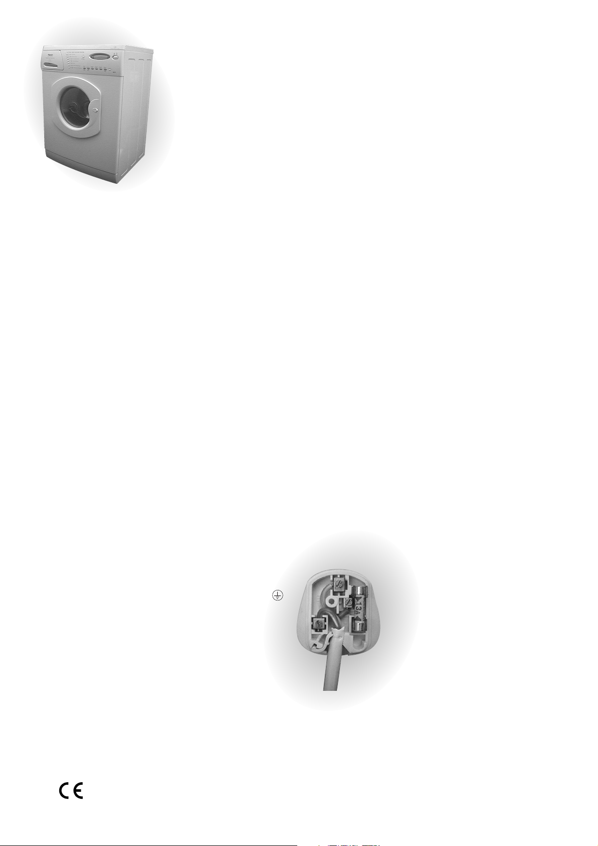
If you change the plug, the colour of
wires in the mains lead may not
correspond with the colour of the
markings identifying terminals in the
plug. You should therefore wire it as
shown (Fig 1).
Green and yellow (Earth)
wire to terminal
marked ‘E’,
symbol , or
coloured green
and yellow.
Blue (Neutral)
wire to terminal
marked ‘N’ or
coloured black.
13A ASTA
approved fuse to
BS1362.
Brown (Live)
wire to terminal
marked ‘L’ or
coloured red.
Cord clamp
Fig 1
Changing the Mains Lead
A special lead can be ordered from Hotpoint Service UK: 08709 066 066 or
Republic of Ireland: 1850 302 200
If you have damaged the existing lead or require a longer one a charge will be made. It is
strongly advised that this work is carried out by a qualified electrician.
CE marking certifies that this appliance conforms to the following EEC directives:Low Voltage Equipment - 72/23/EEC & 93/68 EEC
Electromagnetic Compatibility - 89/336/EEC, 92/31/EEC & 93/68/EEC
2

Contents
Electricity Supply ...................................... 2
Recycling & Disposal Information .............. 3
Installation Instructions
1. Choose a Location................................ 4
2. Remove Transit Brackets ...................... 5
3. Connect to the Water Supply ............... 6
4. Connect to a Drainage System
5. Adjust the Feet ..................................... 7
When you have installed your appliance,
ensure it is ready to use by following the
10 Step Check List on page 7
Getting to know your
Appliance
Index ........................................................ 8
Button Selection
Interlocking Door System
Automatic Features ................................... 9
Wash & Auto Dry
Programme
.................................... 10
Choosing a Dry Programme
Drying Weight Loads
Removal Of Fluff
Items Not Suitable for Tumble Drying
Drying Tips .............................................. 14
Optional Wash/Dry Features
Option Buttons
Automatic Features ............................15-16
The Dispenser Drawer
Index
Choose a Suitable Detergent....................17
Changing the Main Wash Indicator
Dispensing Powder Detergent
Dispensing Liquid Detergent
Dispensing Fabric Conditioner
Using a Dosing Ball.................................. 18
Cleaning
Maintenance Wash
.....................19
Independent Dry
Programme
......................................11
Troubleshooting
Error Messages
............................ 20
............................ 21
Choosing a Wash Programme
Selecting a Prewash
Washing Weight Loads ............................12
Gentle Wash, Rinse & Spin
Hotpoint After Sales
Service
Hotpoint Guarantee
Guarantee Terms & Conditions ............... 23
.............................................. 22
Options for Programme ‘G’
Washcare tips...........................................13
Key Contacts
.................. Back Page
Recycling & Disposal Information
As part of Hotpoint’s continued commitment to helping the environment, Hotpoint reserves the right to use
quality recycled components to keep down customer costs and minimise material wastage.
Please dispose of packaging and old appliances carefully. To minimise risk of injury to children,
remove the door, plug and cut mains cable off flush with the appliance. Dispose of separately to
ensure that the appliance can no longer be plugged into a mains socket.
Retention of this
Instruction Manual
Keep this instruction manual in a
handy place for reference.
It contains important details on
the safe and proper use of your
appliance. If you sell the
appliance, pass it on to someone
else, move house and leave it
behind, make sure that you
provide this manual so that the
new owner can become familiar
with the appliance and safety
warnings.
3

Installation Instructions
IMPORTANT INFORMATION:
●
Do not plug in and switch appliance on at the mains until installation is complete.
●
You may be charged for a service call if a problem with your appliance is caused
by incorrect installation or misuse.
Follow these 5 steps for a trouble free installation:
1. Choose a Location...
2. Remove Transit Brackets...
3. Connect to the Water Supply...
4. Connect to a Drainage System...
5. Adjust the Feet...
1. Choose a Location...
The choice of location for your appliance will influence its performance.
●
Position where possible on a solid floor. Vibration may occur with a wooden floor.
●
Take care with vinyl floor coverings. The weight of the appliance may cause indentations
in some vinyl floor coverings.
●
For your safety and to comply with IEE regulations, you should not install your appliance
in a bath or shower room. Seek professional advice if you wish to do so.
●
Ensure sufficient space is allowed for the appliance. The dimensions should be a
minimum of 600 mm wide, 600 mm deep and 900 mm high.
●
Ensure the electrical socket and water taps are easily accessible and that the water
supply can be isolated if necessary.
4
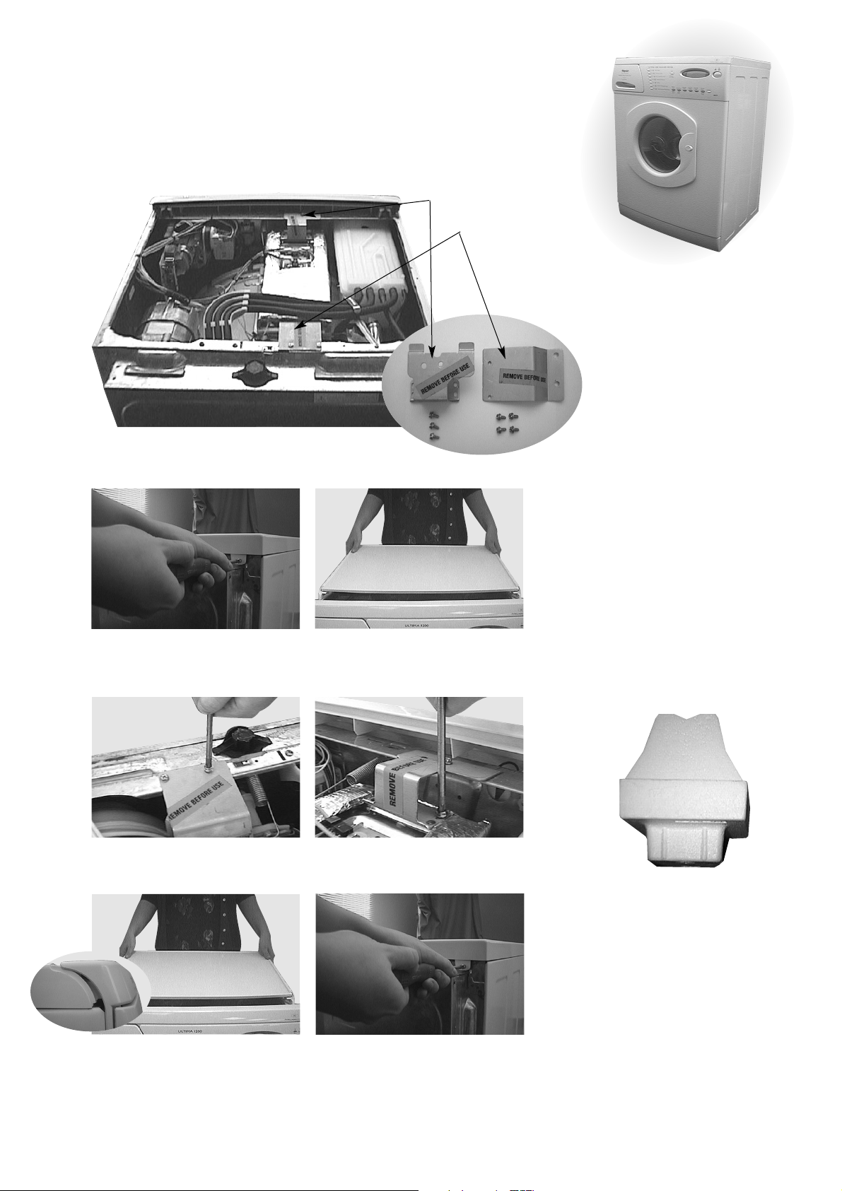
2. Remove Transit Brackets...
Your appliance is fitted with internal transit brackets (Fig 1) which prevents damage to the
appliance during transit. Remove parts (Fig 2) following the instructions below.
Note: It is normal for the door seal to look creased, it will not affect its use.
Front Transit Bracket
Fig 1
Remove 3 screws from back of
1
work top lid, retain.
From rear of appliance, grip
2
sides of work top lid, lift, slide
and pull towards you.
Rear Transit Bracket
Fig 2
WARNINGS
●
Before using appliance,
remove transit brackets,
clamps and screws
Retain parts for future
transportation.
●
After removing the
packaging from the
machine, ensure that
the polystyrene pyramid (shown below) has
come away from the
underside of the
machine, with the
polystyrene base.
Remove 4 screws and rear
3
transit bracket, retain.
Slide and push work top lid into
5
position, ensuring front edge is
correctly located into console.
Remove 3 screws and front
4
transit bracket, retain.
Replace work top lid and 3
6
screws.
If it has not come away,
remove it by tilting the
machine backwards until
the pyramid can be seen
and then remove.
Remember you may be
charged for a service call
if a problem with your
appliance is caused by
incorrect installation or
misuse.
5
3. Connect to the Water Supply...
●
Incoming hot and cold water pressure should be between 3 and 150 psi (21 - 1034 Kpa).
●
The temperature of the incoming household hot water supply should ideally be 60°C and
no higher than 70°C as this could cause damage to both your laundry and appliance.
●
The water supply taps must be easily accessible when the appliance is installed.
●
The appliance must be connected to the appliance water supply using the new hose set
supplied, old hose sets should not be used.
WARNING
●
Do not connect
appliance to a single
outlet instantaneous
water heater.
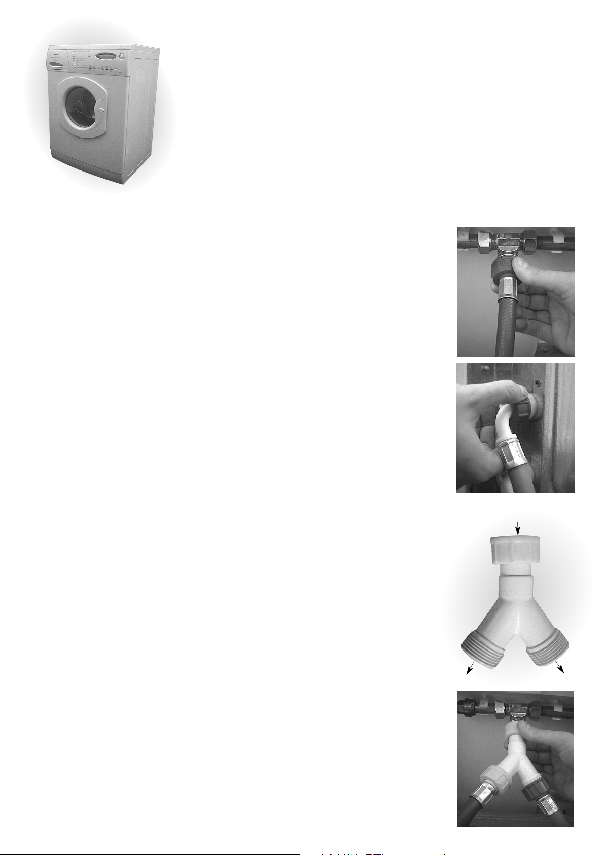
Hot and Cold Fill
1. Connect straight end of supplied red or grey hose to the
HOT water supply tap (Fig 1). Connect straight end of
supplied blue hose to the COLD water supply tap.
2. Hand tighten connectors sufficiently to ensure water
does not leak from the hose connections.
3. Before connecting each of the hoses to the appliance,
confirm water supply is flowing by holding the free end
of each hose in a bucket, turn the relevant water supply
taps on and then off.
4. Connect angled end of red or grey hose to white plastic
inlet valve marked ‘H’ (Fig 2) and angled end of blue
hose to white plastic inlet valve marked ‘C’ at the back
of the appliance.
5. Hand tighten connectors sufficiently to ensure water
does not leak from the hose connections.
6. Turn on water supply taps and check for leaks from the
connectors. In the event of a leak, turn off supply tap,
remove connector and check sealing washer is in place.
Refit connector and tighten. Turn on water supply taps.
Fig 1
Fig 2
Cold Water Supply
Remember you may be
charged for a service call if
a problem with your
appliance is caused by
incorrect installation or
misuse.
6
If you have no hot water supply...
A Cold Fill Adaptor (Fig 3) is available from your local
Hotpoint authorised Service Centre or by calling the
Genuine Parts & Accessories Mail Order Hotline
UK: 08709 077 077 or Republic of Ireland: (01) 842 6836.
Fitting a Cold Fill Adaptor
1. Connect straight ends of supplied hoses to the Cold Fill
Adaptor (Fig 3).
2. Connect adaptor to the cold water supply tap (Fig 4).
3. Before connecting the hoses to the appliance hold the
free end of each hose in a bucket, gently turn on the tap
to confirm the water supply is flowing. Turn off the tap.
4. Connect angled end of the supplied hoses to white
plastic inlet valves marked ‘H’ and ‘C’ at the back of the
appliance.
5. Hand tighten the connectors sufficiently to ensure water
does not leak from the hose connections. Turn on water
supply taps.
Inlet to
machine
Fig. 3
Inlet to
machine
Fig. 4
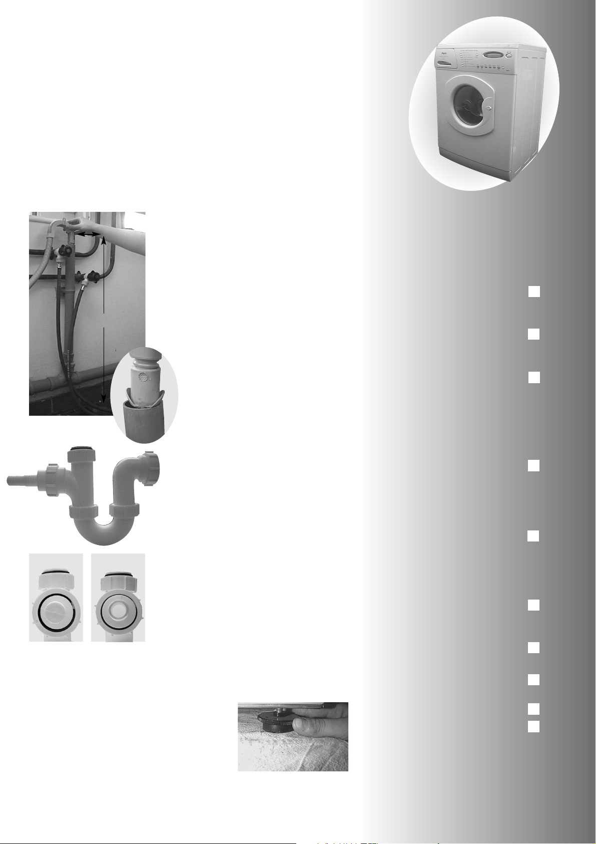
4. Connect to a Drainage
System...
●
Do not remove hooked end support from drainage hose.
●
Do not position standpipe near an electrical outlet.
●
For drainage into a standard work top sink ensure outlet pipe has a
minimum bore of 32 mm. To avoid syphoning ensure the end of the
drainage hose is above the water level in the sink. If your sink is inset, the
front edge of the basin must be less than 75 mm from the front edge of
your work top.
Fig 1
Fig 3
Fig 4 - Before
500 mm
Fig 4a - After
Fig 2
We recommend one of the following
drainage methods:-
Standpipe
Note: Ensure the standpipe has a
minimum diameter of 38 mm.
1. Ensure top of standpipe is positioned
at least 500 mm from the floor (Fig 1).
2. Untie the end of the GREY drainage
hose from the rear of the appliance
and place approximately 100 mm into
the standpipe.
3. If the end of GREY drainage hose is
fitted with ‘Retaining Flaps’, ensure
that they are fully inserted into the
standpipe as shown (Fig 2).
Sink Waste System
Note: Ensure the sink outlet pipe has a
minimum diameter of 32 mm.
1. Untie the end of the GREY drainage
from the rear of the appliance.
2. Reposition ‘Hooked End Support’ as
required along GREY drainage hose.
3. If fitting an under sink waste disposal
unit (Fig 3), cut out the membrane,
bung or blanking plug (Fig 4 and 4a).
4. Attach the GREY drainage hose to
the under sink waste disposal unit
securely, using a Jubilee clip.
5. Raise the hose to a minimum height
of 800 mm to avoid syphoning.
When you have installed your
appliance, ensure it is ready to use by
following this 10 Step Check List
1. Dispose of packaging safely,
see ‘Recycling Information’
on page 3.
2. Position appliance close to
electrical/water supply see
‘Location’ on page 4.
3. Remove transit brackets, screws
and spacers see ‘Remove
Transit Brackets’ on page 5.
4. Connect supplied hoses to
appliance water supply, confirm
water is flowing before connecting
to the appliance inlet valves
see ‘Water Supply’ on page 6.
5. Untie drainage hose at rear of
appliance and connect to either
a standpipe or sink waste drainage
system see ‘Drainage’ opposite.
6. Untie mains lead at rear of
appliance and plug into
electrical supply via a switched
socket, see ‘Electrical Supply’ on
page 2.
7. Position appliance, taking care
not to kink or damage hoses
at rear of appliance.
8. Stabilise the appliance, see
‘Adjusting the feet’ opposite.
Check List
Check List
5. Adjust the Feet...This must
only be done when the machine is upright
●
Release locking rings on the two front feet.
●
Screw feet in or out until appliance is
standing firm and level.
●
Ensure all feet are in firm contact with the
floor and the machine is not leaning forward.
●
Tighten the locking rings on the front feet to the underside of the cabinet.
Note: Your appliance may become noisy or move about the floor if it has
not been stabilised.
9. Turn on the water supply
to the appliance.
10.Switch on at plug socket.
Your appliance is now ready to use,
refer to ‘Getting to Know your
Appliance’ on page 8 to familiarise
yourself with the appliance.
10 Step
10 Step
7
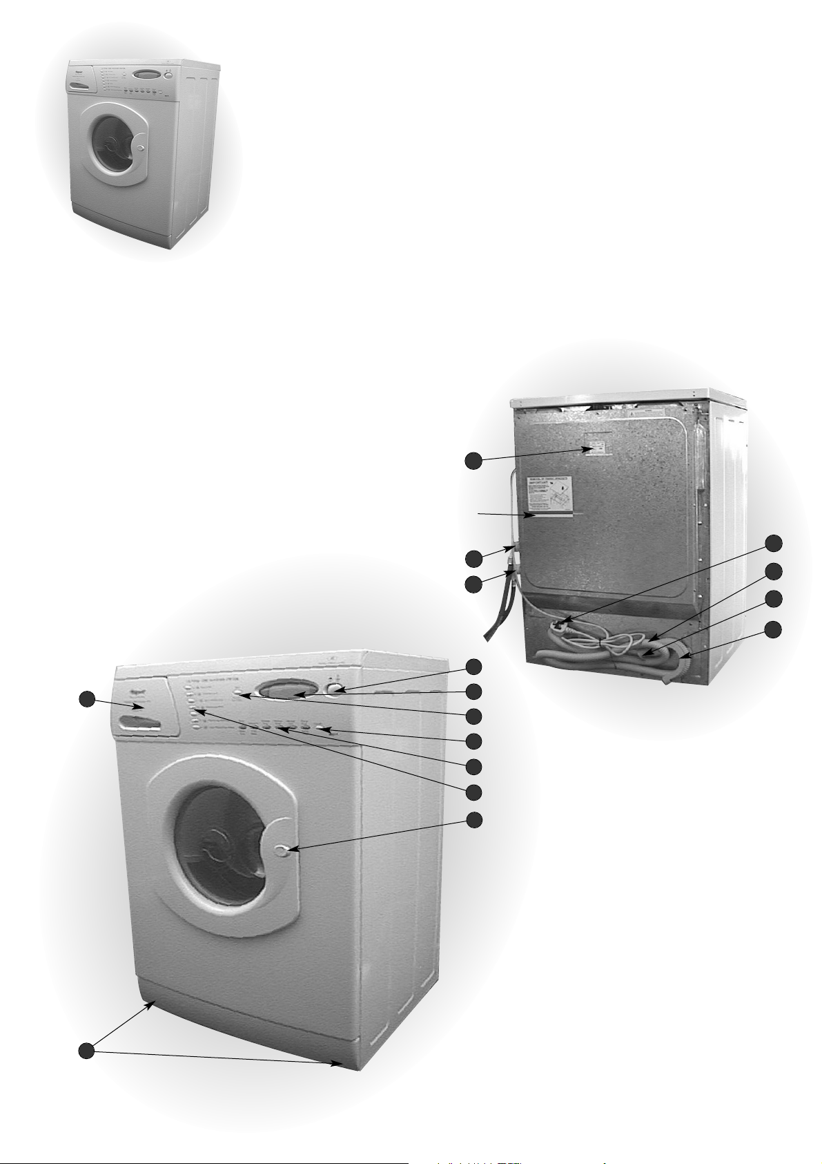
Getting to Know Your
Appliance
10
Red line indicates minimum
height of drainage hose
11
Model WD71
8
12
1
2
3
13
14
15
16
4
5
6
7
9
8
Index
Front
1. Mains On/Off Button
2. Infobubble™ Display
3. Start, Buzzer/Time Delay Button
4. Cancel Button
5. Optional Wash/Dry Feature Buttons
6. Wash Programme Buttons
7. Door Handle & Release Button
8. Detergent/Fabric Conditioner Drawer
9. Adjustable Feet
Back
10. Rating Plate
11. Hot Water Inlet Point and supplied Hose
(Red or Grey)
12. Cold Water Inlet Point and supplied Hose (Blue)
13. Mains Cable
14. Drainage Hose
15. Retaining Flaps
16. Hooked End Support
 Loading...