

Hotpoint WD420P, WD420G, WD420T, WD440P, WD440G Service Information
Information
Indesit Company UK Ltd
© 2006 Reg. Office: Peterborough PE2 9JB. Registered in London: 106725
Service
Hotpoint
Aquarius
Washer
Dryers
Models Commercial
Code
WD420P 31127
WD420G 31128
WD420T 31126
WD440P 34189
WD440G 36234
5407170 Issue 6 Aug. 2006

2
SAFETY NOTES & GENERAL SERVICING ADVICE
1. This manual is NOT intended as a comprehensive repair/maintenance guide to the appliance.
2. It should ONLY be used by suitably qualified persons having technical competence applicable
product knowledge and suitable tools and test equipment.
3. Servicing of electrical appliances must be undertaken with the appliance disconnected
(unplugged) from the electrical supply.
4. Servicing must be preceded by Earth Continuity and Insulation Resistance checks.
5. Personal safety precautions must be taken to protect against accidents caused by sharp edges
on metal and plastic parts.
6. After servicing the appliance must be rechecked for Electrical Safety. In the case of appliances
which are connected to a water supply (i.e.: Washing Machines, Dishwashers & Food Centres
etc.) checks must be made for leaks from seals gaskets and pipe work and rectification carried
out where necessary.
7. It can be dangerous to attempt 'DIY' repairs / maintenance on complex equipment and the
Company recommends that any problem with the appliance is referred to its own Service
Organisation.
8. Whilst the Company has endeavoured to ensure the accuracy of the data within this publication
they cannot hold themselves responsible for any inconvenience or loss occasioned by any error
within.
3
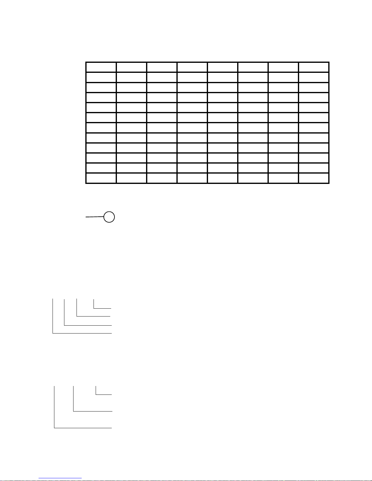
MANUFACTURING DATE CODE REFERENCE CHART
This example shows that the machine was
manufactured in MARCH 2004.
SERIAL NUMBER / INDUSTRIAL CODE EXPLANATION
1986 1987 1988 1989 1990 1991 1992 1993
1994 1995 1996 1997 1998 1999 2000 2001
2002 2003 2004 2005 2006 2007 2008 2009
Jan 01 13 25 37 49 61 73 85
Feb 02 14 26 38 50 62 74 86
March 03 15 27 39 51 63 75 87
April 04 16 28 40 52 64 76 88
Ma
y
05 17 29 41 53 65 77 89
June 06 18 30 42 54 66 78 90
Jul
y
07 19 31 43 55 67 79 91
Aug 08 20 32 44 56 68 80 92
Sept 09 21 33 45 57 69 81 93
Oct 10 22 34 46 58 70 82 94
No
v
11 23 35 47 59 71 83 95
Dec 12 24 36 48 60 72 84 96
First 2 digits of the serial number indicate production date
Date Code 27 120054
Serial Number Example
3 10 02 0895
Four remaining digits = Build number that day 895
th
built
Third two digits = Day of manufacture 2
nd
of month
Second two digits = Month of manufacture October
First digit = Year of manufacture 2003
Industrial Code Example
37 24455 0010
Last four digits = 0000 original production.
Second five digits = COMMERCIAL CODE*
First two digits = Factory of origin
* Vital for correct model information and system identification
Other numbers denote major production changes

4
INDEX
Safety & Servicing Notes. . . . . . . . . . . . . . . . . . . . . . . . . . . . . . . . . . . . . . . . . .2
Manufacturing Date Code Chart & Serial Number Information . . . . . . . . . . . 3
Development History . . . . . . . . . . . . . . . . . . . . . . . . . . . . . . . . . . . . . . . . . . . . . 4
Specifications. . . . . . . . . . . . . . . . . . . . . . . . . . . . . . . . . . . . . . . . . . . . . . . . . . . 5
Installation . . . . . . . . . . . . . . . . . . . . . . . . . . . . . . . . . . . . . . . . . . . . . . . . . . 6 - 8
Controls, Options and Wash Programme details . . . . . . . . . . . . . . . . . . 9 - 13
Wiring Details
Wiring Connections & Wiring Diagram - Before D.C. 40 . . . . . . . . . 14 - 15
Wiring Connections & Wiring Diagram - After D.C. 39. . . . . . . . . . . 16 - 17
Wiring Diagram - After Serial Number 60508.0000 . . . . . . . . . . . . . . . . . . 18
Wiring Diagram Legend. . . . . . . . . . . . . . . . . . . . . . . . . . . . . . . . . . . . . . . . . . 19
Auto Test Set Up, Test Sequence, Diagnostics & Error Codes . . . . . . 20 - 23
Dismantling Instructions . . . . . . . . . . . . . . . . . . . . . . . . . . . . . . . . . . . . . 24 - 30
EEProms . . . . . . . . . . . . . . . . . . . . . . . . . . . . . . . . . . . . . . . . . . . . . . . . . . . . . . 31
DEVELOPMENT HISTORY
September 2004
Date Code 33 Aquarius versions WD420 enter full production.
November 2004
Date Code 35 WD440P - General tactical model, same as WD420 but with 1400 rpm spin.
February 2005
Date Code 38 WD440G first produced.
April 2005 Models WD420 & WD440
Date Code 40 Change to Cold Fill and deletion of heater box fluff filter.
On 25
th
April 2005 (Date Code 40), this range of washer dryers changed from
Hot and Cold Fill to Cold Fill only. Along with this change a modification was
made to the tumble dryer heater box assembly with the introduction of a
straight heating element, this to improve the air flow through the heater box.
This change enables the removal of the heater box fluff filter and deletion of the
flushing valve and hose. The thermistor, one-shot cut out and fan assembly are
not affected. The 4-way valve is replaced by a 3-way valve and the hot supply
hose is deleted.
A new file setting (EEPROM) is used for cold fill machines, but the consumer
programmes remain the same for both Hot and Cold and Cold fill machines.
The changes to the heater box assembly does not effect the EEPROM file
settings.
May 2006 Model WD420 & WD440
(S/N 60508.0000) Re-introduction of flushing valve style heater box assembly.
On 8 May 2006 (S/N 60508.0000), the flushing valve and fluff filter was
re-introduced in production, along with spiral element, metal fan, externally
mounted dryer motor and thermal fuse cable, which is attached to the heater
box upper casing in place of the one shot cut-out device.
5
SPECIFICATIONS
Models Covered WD420 Washer Dryer
WD440 Washer Dryer
Colours P = Polar, G = Graphite, T = Sandstone
Country of Origin Great Britain
Electrical Supply 230 Volts AC @ 50Hz Fuse 13amp
Energy Energy Class: B
Washing Performance Class: A @ 40°C
Energy Consumption 1.02 KWh / Cycle @ 60°C Cotton
Water Consumption Washing Only = 55 Litres @ 60°C Cotton
Wash Load 6 kg Cottons
Washing & Drying Load 5.0 kg + 5.0 kg Cottons
Spin Speed WD420 - 1200 rpm maximum WD440 - 1400 rpm maximum
Control PCB 220/230Volt 50/60Hz Type Merloni EVO 2
Wash Heater 1800 Watts @ 230 volts Resistance 30 Ω approx.
Dryer Heater 1200 Watts @ 230 volts Resistance 43 Ω approx.
Thermistor NTC - Wash Resistance: 20 KΩ @ 20°C
Thermistor NTC - Dryer Resistance: 26 KΩ @ 20°C
Water Supply Hot & Cold Valves - Coil Resistance 3.8 KΩ
Max Pressure = 1 Mpa (10bar)
Minimum Pressure = 0.05 Mpa (0.5bar)
Motor - Wash Universal Series Wound 230V 50Hz AC with tapped field
Motor - Dryer Fan 230 Volt 50 Hz Resistance approx. 45 Ω
Pump 2 Pole Synchronous
220 / 240 Volt 25 Watt, Resistance = 165 Ω
Maximum Head 1.4 metres
Flow rate @ 0.9 metres / 30 Litres per minute
Door Lock P.T.C. Bimetallic - Time Delay approx 2 minutes
Torque Settings Outer Drum = 8Nm
Upper Balance Weight = 18 Nm
Lower Balance Weight = 24 Nm
Heater Box to Drum = 12Nm
Heater Box Top to Bottom = 8Nm
Dimensions Height 850 mm Width 595 mm
Depth 600 mm Weight 66 kg. Packed approx 69 kg
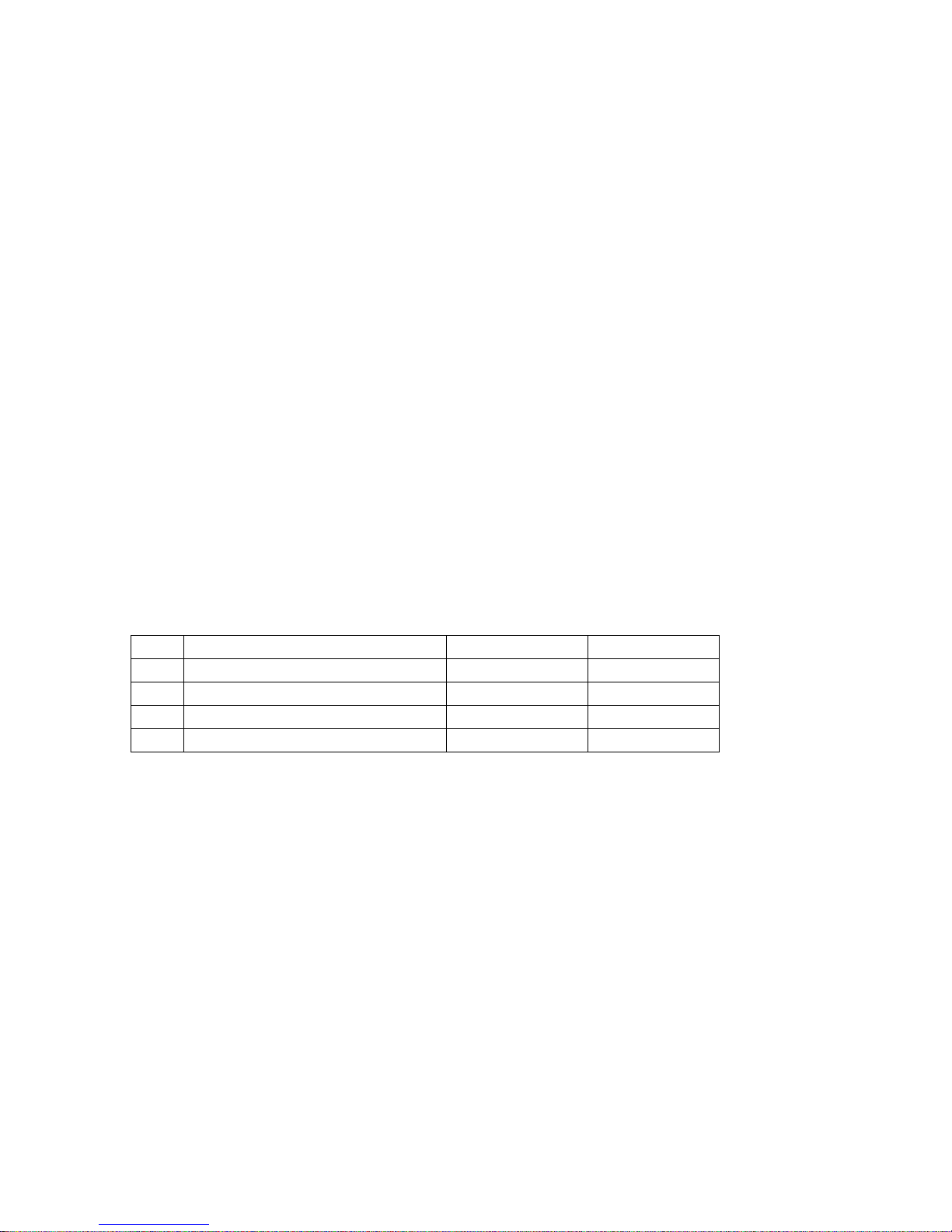
Pins Resistances FHP CESET
5-6 Armature Varies with brush-gear 1.5 Ω ± 8% 1.78 Ω ± 7%
3-4 Full Field 1.26 Ω ± 8% 1.25 Ω ± 7%
3-7 Tapped Field 0.47 Ω ± 10% 0.41 Ω ± 7%
1-2 Tacho 16 Pole (8 pairs) 135 Ω ± 10% 68.7 Ω ± 7%
6
INSTALLATION
Unpacking
1. Unpack the washing machine.
2. Check whether the washing machine has
been damaged during transport. If this is the
case, do not install it.
Remove the polystyrene base
The vertical block part of the base (see below)
should have stayed intact when the base was
removed. If it has broken off and is still inside
the machine, carefully lay the machine on its
side, onto the polystyrene top cap and then
remove the block.
Warning:
Packaging materials are not childrens toys.
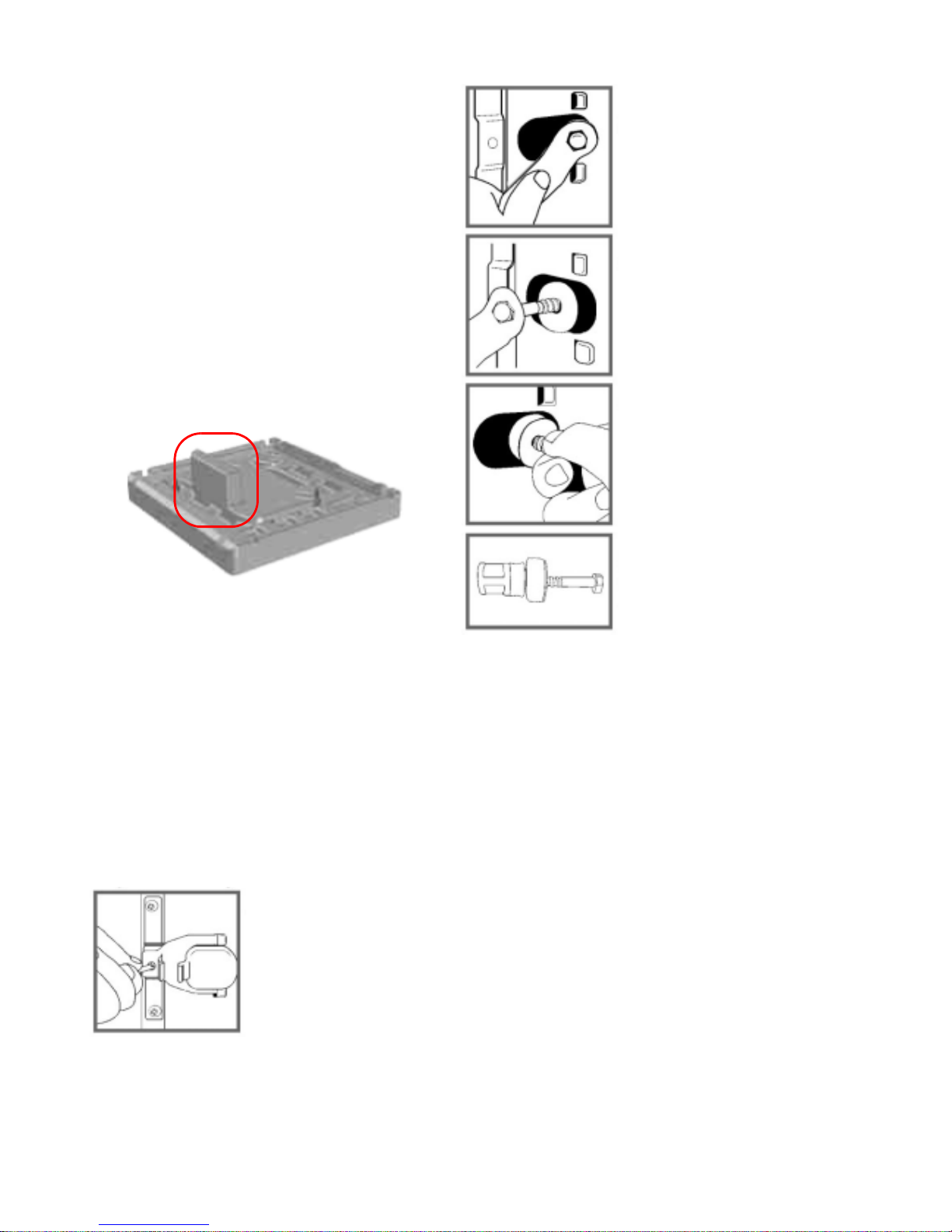
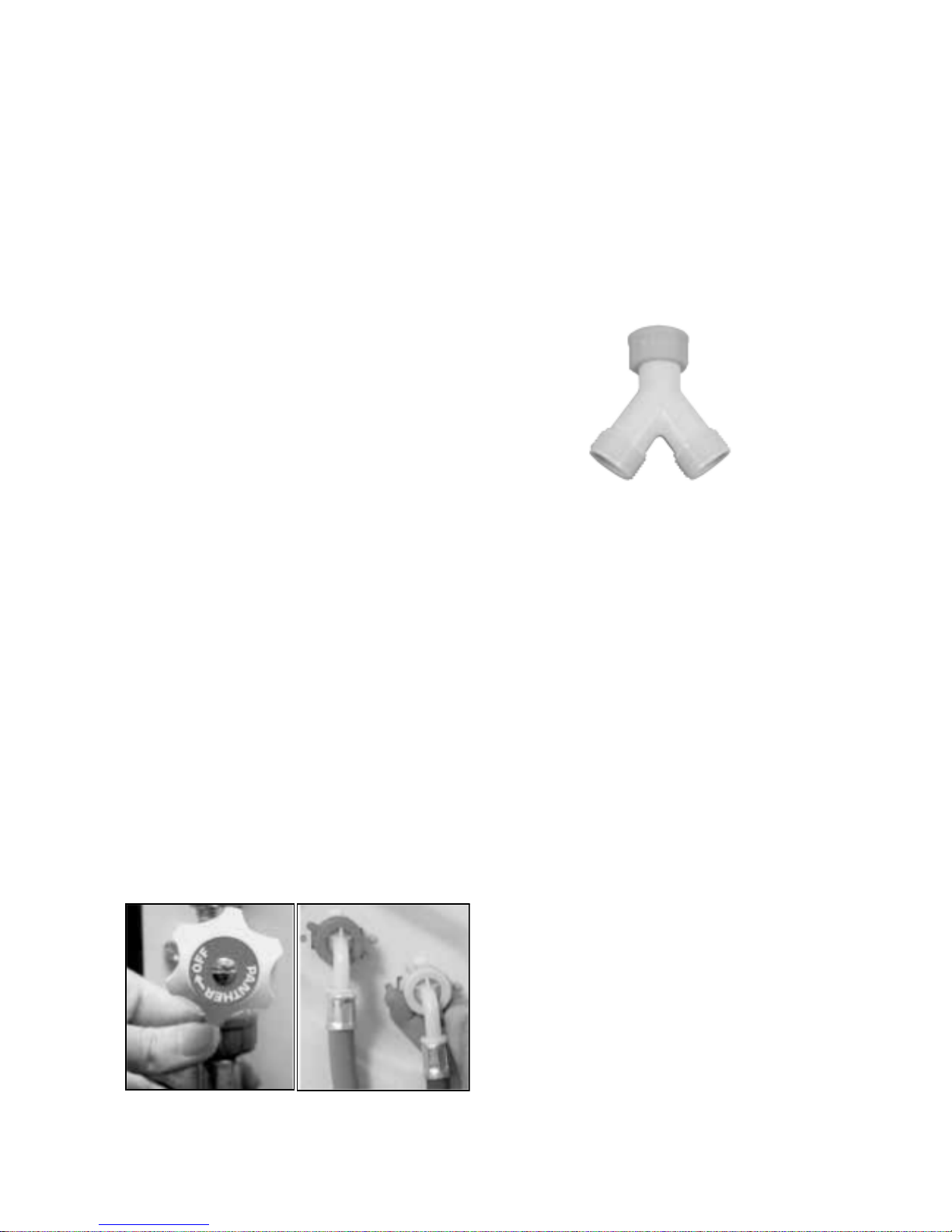
Remove the transit fixings
Follow these instructions to remove the TWO
transit fixings. IMPORTANT: Situated one either
side of the rear panel, both transit bolts (complete
with spacers) MUST be removed before use.
Failure to do so may cause damage to the
machine!
1. Use a crosshead
screwdriver to
remove the plastic
cover.
Vertical block
polystyrene
base
For safety, replace both plastic covers over the
holes left by removing the two bolts.
Levelling
1. Install the washing machine on a flat sturdy
floor, without resting it up against walls,
cabinets etc.
2. Compensate for any unevenness by
tightening or loosening the adjustable front
feet. The angle of inclination, measured
according to the worktop must not
exceed 2°.
Levelling the appliance correctly will provide it
with stability and avoid any vibrations, noise
and shifting during operation. If it is placed on
a fitted or loose carpet, adjust the feet in such
a way as to allow enough room for ventilation
beneath the washing machine.
2. Unscrew the bolt
using a 13 mm
spanner.
3. STOP when 3
threads can be
seen.
4. Hold, slide and pull
to remove.
! It is important the
transit bolt and
spacer come out
intact
(see image left).
7
Connecting to the Water Supply
WARNINGS:
The temperature of the hot water supply
should ideally be 60°C and no higher than
70°C as this could cause damage to the
laundry and the machine. Applies to
products produced prior to Date Code 40.
Do not connect the machine to a single
outlet instantaneous water heater.
The hot and cold water pressure should be
between 3 and 150 psi (21 - 1034 kPa).
Incorrect pressures could lead to flooding.
The water supply taps should be accessible
when the machine is installed.
Before connecting the fill hoses, check that
water is running from the water supply taps
you will use for the machine.
Connect the washing machine to the water
supply using the fill hoses fitted to the
machine.
Do not use old hoses.
Hot & Cold Fill - Cold fill only from D.C. 40
1 Unclip the grey and blue fill hoses from
the back of the machine.
2 Connect the free end of the grey fill hose
to the HOT water supply (see figure1).
Connect the free end of the blue fill hose
to the COLD water supply.
3 Turn on the water supply and check for
leaks. If there is a leak, turn off the water
supply, remove the connector and check
that the sealing washer is in place.
Refit the connector and tighten it.
Turn on the water supply.
4 When moving the machine into its final
position, make sure that the hoses are not
trapped or kinked.
Fig. 1 Fig. 2
If the fill hoses are too short:
Longer fill hoses are available. Remove the
existing fill hoses from the inlet valves on the
back of the machine and fit the new longer fill
hoses as shown above with the angled ends
of the hoses connected to the machine
(see Fig. 2).
If no hot water supply is available or the hot
water pressure is low, a cold fill adaptor
(Fig. 3) and fitting instructions are available.
Applies to products produced prior to D.C. 40.
Electrical connections
Before plugging the appliance into the
mains socket, make sure that:
- the socket is earthed and in compliance
with the applicable law.
- the supply voltage is included within the
values indicated in the Specifications page.
- the socket is compatible with the washing
machines plug. If this is not the case,
replace the socket or the plug.
Location
! The washing machine should not be
installed in an outdoor environment, not
even when the area is sheltered, because it
may be very dangerous to leave it exposed
to rain and thunderstorms.
! When the washing machine is installe d, the
mains socket must be within easy reach.
! Do not use extensions or multiple sockets.
! The power supply cable must never be
bent or dangerously compressed.
! The power supply cable must only be
replaced by an authorised engineer.
8
Drainage Connections
Take care when you remove the drain hose
from the clips on the back of the machine.
All machines are tested with water before they
leave the factory so a small amount of water
may still be in the hose.
Do not remove the hooked end support from
the GREY drainage hose when using any of
the drainage methods detailed below. You
may need to reposition it as required along the
drainage hose.
For drainage into a standard work top sink,
ensure the outlet pipe has a minimum
diameter of 32 mm. If the sink is inset, the front
edge of the basin must be less than
75 mm from the front edge of the worktop, so
that the drain hose will hook securely into the
sink.
Unclip the drainage hose from the back of the
machine and hook over into the sink. Make
sure that the sink is free of any obstructions
and that the sink plug can not fall into the sink,
preventing the water from draining away
freely. Pumped out water may be very hot.
We recommend one of the following drainage
methods:
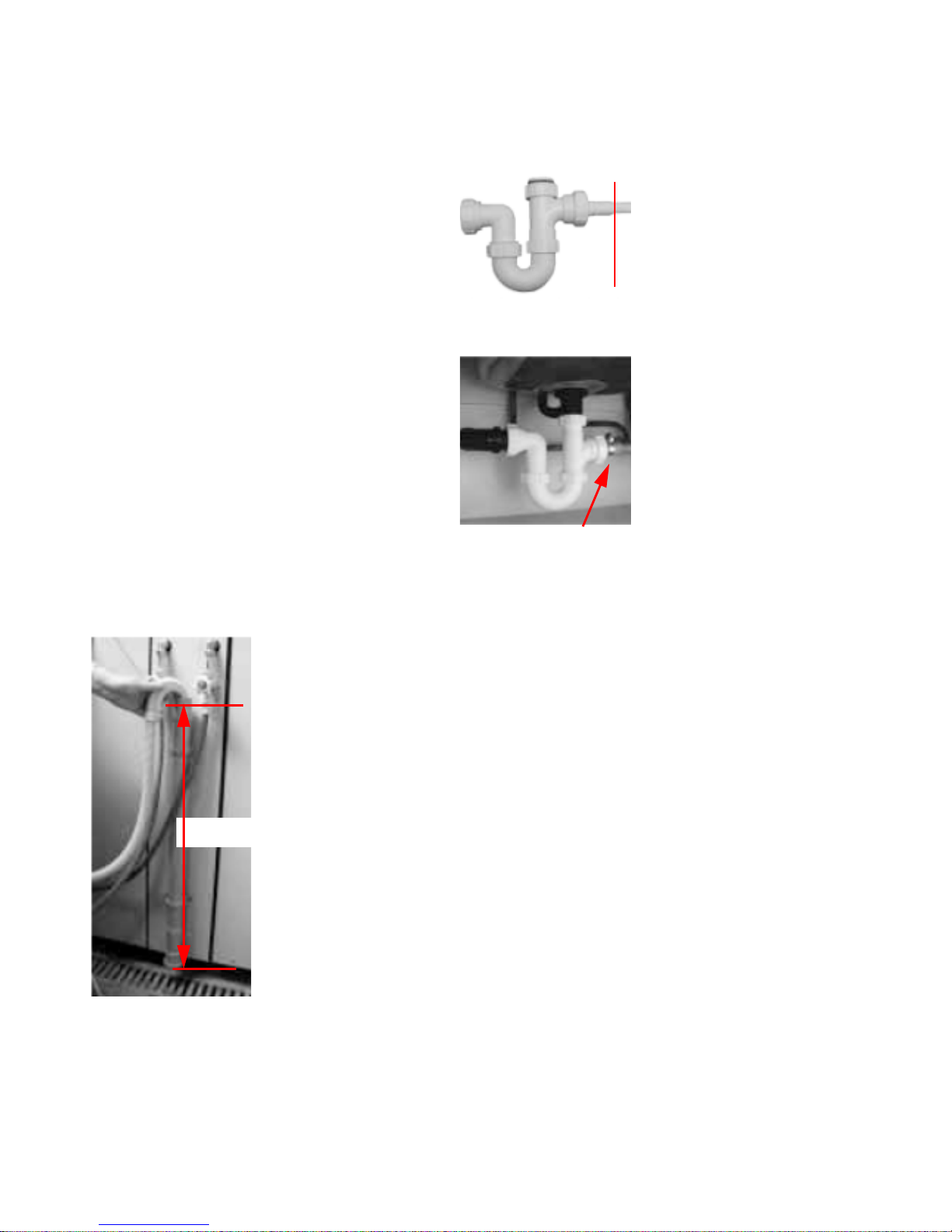
Stand pipe Fig. 1 1 Make sure that the
standpipe has a
minimum diameter
of 38 mm.
2 Remove the
drainage hose from
the clips on the
back of the
machine.
3 Make sure that the
top of the standpipe
is positioned at
least 500 mm from
the floor (see
Fig.1).
Use the plumbing
indicator line label
on the back of the
machine as a
guide.
4 Place the drainage hose approximately
100 mm into the standp ipe.
500 mm
Extending the drainage hose
If the GREY drainage hose is too short, a
longer drainage hose is available from our
Genuine Parts & Accessories Mail Order
Hotline.
WARNING!
The company denies all liability if and when
these warnings are not respected.
The first wash cycle
Once the appliance has been installed and
before you use it for the first time, run a
wash cycle without detergent and no
laundry, setting the 90°C programme
without a pre-wash cycle.
Under Sink
Waste System
Fig.2
Fig.3
1 Cut out the
membrane, bung or
blanking plug (see
Fig. 2).
2 Unclip the drainage
hose from the back
of the machine.
3 Move the hooked
end support along
the drainage hose
as required.
4 Attach the drainage
hose securely to
the under sink
drainage unit, using
a hose clip (see
Fig. 3).
5 Raise the hooked
end support up to at
least 800 mm to
avoid water being
drawn back into the
machine.
cut
off
end
Hose clip
9
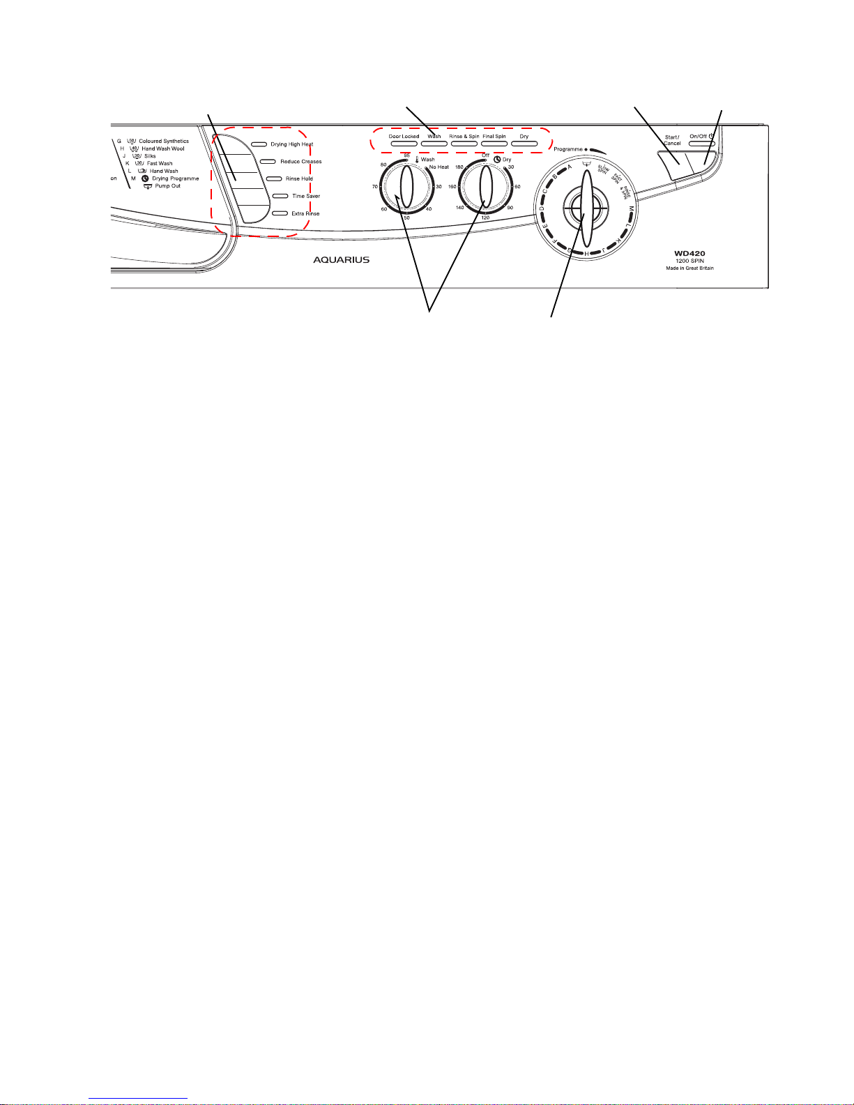
Controls
On-Off / Selecting a programme
The machine is switched on by pressing the 'On/Off' button for 2 seco nds. All the indicator lig hts will
light up for a few seconds and the 'Door Locked' indicator light will flash once.
Turn the programme selector dial to the desired programme. Load the laundry and detergent.
Select the options you require.
Press the 'Start/Cancel' button for 2 seconds to start the programme.
To stop or change a programme
Press the 'Start/Cancel' button for 2 seconds.
Select 'Pump Out' on the programme selector dial.
When the machine has finished emptying, turn the programme selector dial to the new pr ogramme.
Press the 'Start/Cancel' button to start the programme.
If you cancel a hot wash programme, take care when removing the laundr y, it migh t still be ve ry hot.
Progress indicator lights
These will light up when you choose a programme, to indicate the progress of the selected
programme. When started, the first light in the cycle will stay lit and as the programme progresses,
successive lights will come on until the programme finishes.
Door Locked indicator light
The ‘Door Locked’ indicator light will c ome on two sec onds afte r yo u p res s the 'Star t/Cance l' butto n
and will stay lit throughout the programme. A short time after the programme has finished the
indicator light will go out and you can then open the door.
Selected programmes will not start if the door is not cl osed properly, the 'Door Lo cked' indicator light
will flash to show this. Push the door shut until you hear the catch click.
Button Selection:
To select an option, press the button and you will see a light come on alongside the button.
Press again to cancel, and the light will go out.
Option Buttons
Progress Indicator Lights Start/Cancel
On/Off
Programme Selector Dial
Variable Control(s)
10
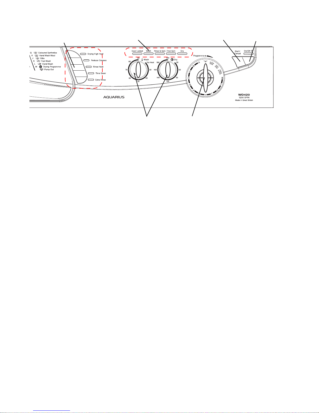
Options
Options are selected by pressing the button and confirmed by illumination of the LED.
Drying High Heat
The default setting is LOW heat. By selecting this allows HIGH heat for tumble drying.
Reduced Creases
Changes wash action and slightly increases drum speed on cotton programmes and removes end
of wash spin with a reduced speed on final spin on synthetic programmes.
Available on programmes C, E, G and Rinse and Spin programmes
Rinse Hold
Clothes will be suspended in cold water at the end of the final rinse. To complete the programme,
press the button when the LED is flashing
This option is not available on programmes A, H, K, L and Spin only
Time Saver
Saves programme time by up to a third depending on programme selected and is achieved by
reducing wash run times.
This option is only available on programmes B, D, G and H.
Extra Rinse
Adds an extra rinse to the programme
This option is not available on programmes A, E, H, J, K, L or Spin only
Variable Wash Temperature Control - Selected by Rotary Knob
Enables a lower wash temperature and No Heat to be selected
Note; if the dial is left at the maximum temperature setting the programme will be washed at the
maximum temperature for the programme selected
Variable Tumble Drying Time - Selected by Rotary Knob
Enables the required drying time to be chosen.
Maximum 180 minutes plus 20 minutes Cool Tumble.
Option Buttons
Progress Indicator Lights Start/Cancel
On/Off
Programme Selector Dial
Variable Control(s)
 Loading...