

Hotpoint SE89PG, SH89PX Operating Instructions Manual

SY89PG
SE89PG X
SE89PG
SH89PX
GB
OVEN
Contents
Installation, 2
Positioning
Electrical connection, 3
Data plate
Description of the appliance, 4
Overall view
Control panel
Display
Start-up and use, 5
Setting the clock
Setting the timer
Starting the oven
Cooking modes, 6-8
Cooking modes
Programming cooking
Practical cooking advice
Cooking advice table
Precautions and tips, 9
General safety
Disposal
Respecting and conserving the environment
Care and maintenance, 10-12
Switching the appliance off
Cleaning the appliance
Cleaning the oven door
Replacing the light bulb
Automatic cleaning using the FAST CLEAN function
Assistance
Guarantee, 13
After Sales Service, 14
English, 1
Operating Instructions
GB
2
GB
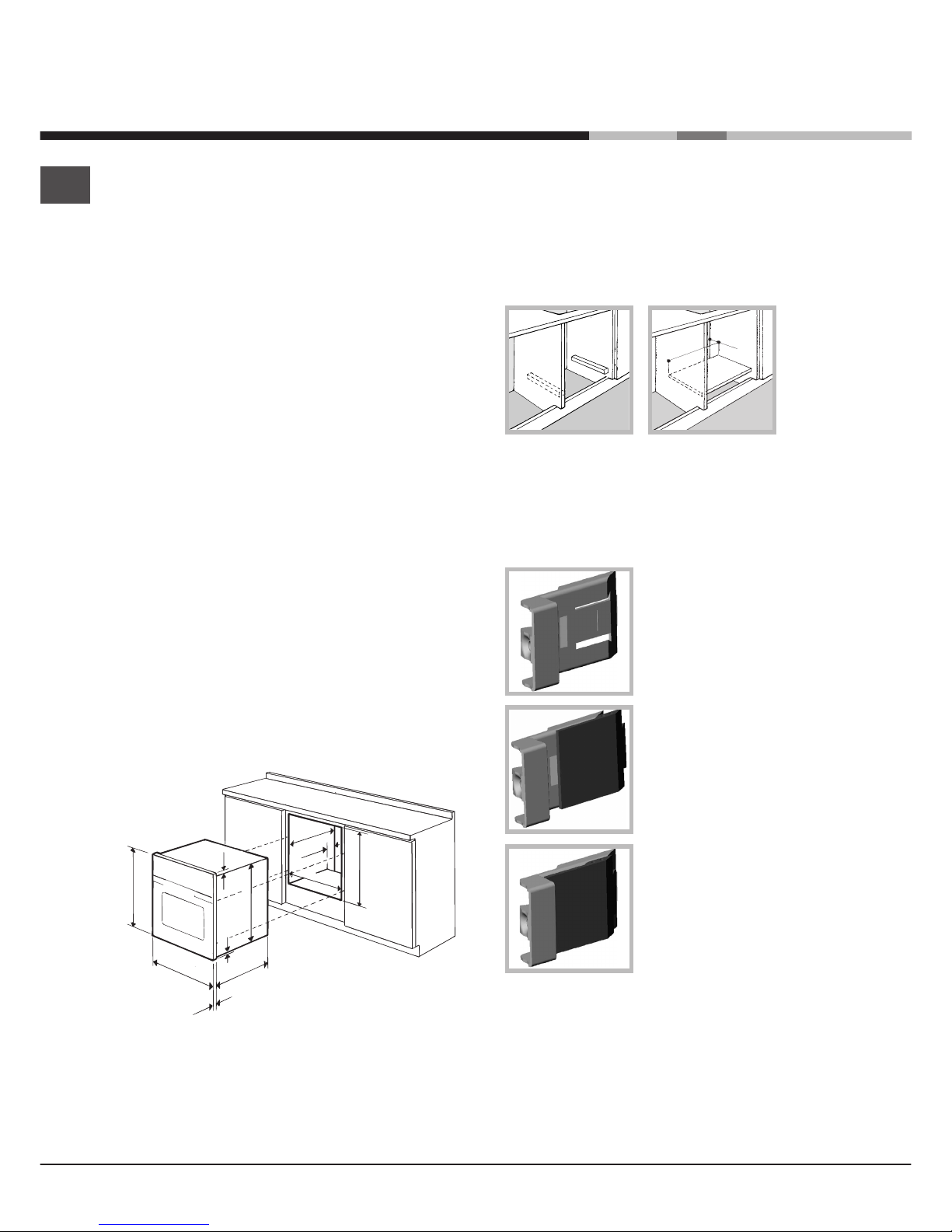
Ventilation
To ensure adequate ventilation is provided, the back
panel of the cabinet must be removed. It is
advisable to install the oven so that it rests on two
strips of wood, or on a completely flat surface with
an opening of at least 45 x 560 mm (
see diagrams
).
Centring and fixing
Position the 4 tabs on the side of the oven, in line
with the 4 holes on the outer frame. Adjust the tabs
according to the thickness of the cabinet side panel,
as shown below:
20 mm thick: take off the
removable part of the tab
(
see diagram
).
18 mm thick: use the first
groove, which has already
been set in the factory
(
see diagram
).
16 mm thick: use the second
groove (
see diagram
).
Secure the appliance to the cabinet by opening the
oven door and inserting 4 screws into the 4 holes on
the outer frame.
!!
!!
! All parts which ensure the safe operation of the
appliance must not be removable without the aid of
a tool.
!!
!!
! Before operating your new appliance please read
this instruction booklet carefully. It contains
important information concerning the safe operation,
installation and maintenance of the appliance.
! Please keep these operating instructions for future
reference. Pass them on to possible new owners of
the appliance.
Positioning
!!
!!
! Keep packaging material out of the reach of
children.
It can become a choking or suffocation hazard. (
see
Precautions and tips
).
!!
!!
! The appliance must be installed by a qualified
professional in accordance with the instructions
provided. Incorrect installation may cause harm to
people and animals or may damage property.
Built-in appliance
Use the appropriate cabinet to ensure that the
appliance functions properly.
• The panels adjacent to the oven must be made of
heat-resistant material.
• Cabinets with a veneer exterior must be
assembled with glues which can withstand
temperatures of up to 100°C.
• to install the oven under the counter (
see diagram
)
or in a kitchen unit, the cabinet must have the
following dimensions:
!!
!!
! The appliance must not come into contact with
electrical parts once it has been installed.
The indications for consumption given on the data
plate have been calculated for this type of
installation.
595 mm.
595 mm.
24 mm.
545 mm.
5 mm.
567 mm.
23 mm.
593 mm.
45 mm.
558 mm.
547 mm. min.
Installation
560 mm.
45 mm.
3
GB
TABLE OF CHARACTERISTICS
Dimensions
width 43.5 cm
height 32 cm
depth 40 cm
Volume 56 l
Dimensions *
width 43.5 cm
height 32 cm
depth 41.5 cm
Volume * 58 l
Electrical
connections
volt age: 220 - 240 V~ 5 0/60 Hz
maximum p ower absorbed 2800 W
(se e data plat e)
ENERGY
LABEL
Directi ve 2002/40/EC on the label of
electr ic oven s. Sta ndard EN 503 04
Energy consumption for Nat ural
convection – heating mode:
Traditional mode
Decla red energy consumpti on for
Forced convecti on Class – heat ing
mode: Baking
Thi s applia nce conf orms to t he
following Eur opean Economic
Commu nit y directi ves: 2006/95/EEC
dat ed 12/1 2/06 (Low Vol tage) and
subsequent amendment s –
2004/108/ EEC dated 15/12 /04
(El ectromagnet ic Compa tibility) and
subsequent amendment s 93/ 68/ EEC dated 22/07/93 and
subsequent amendment s.
2002/96/EC and subsequent
amendments.
1275/2008 stand-by/of f mo de
* With glass panel fitted to the insi de of the door
Electrical Connection
Electrical connection
The electrical connection to the mains must be made
on the appliance. The power voltage and frequency
are as indicated on the rating plate.
!
THIS APPLIANCE MUST BE EARTHED.THIS APPLIANCE MUST BE EARTHED.
THIS APPLIANCE MUST BE EARTHED.THIS APPLIANCE MUST BE EARTHED.
THIS APPLIANCE MUST BE EARTHED.
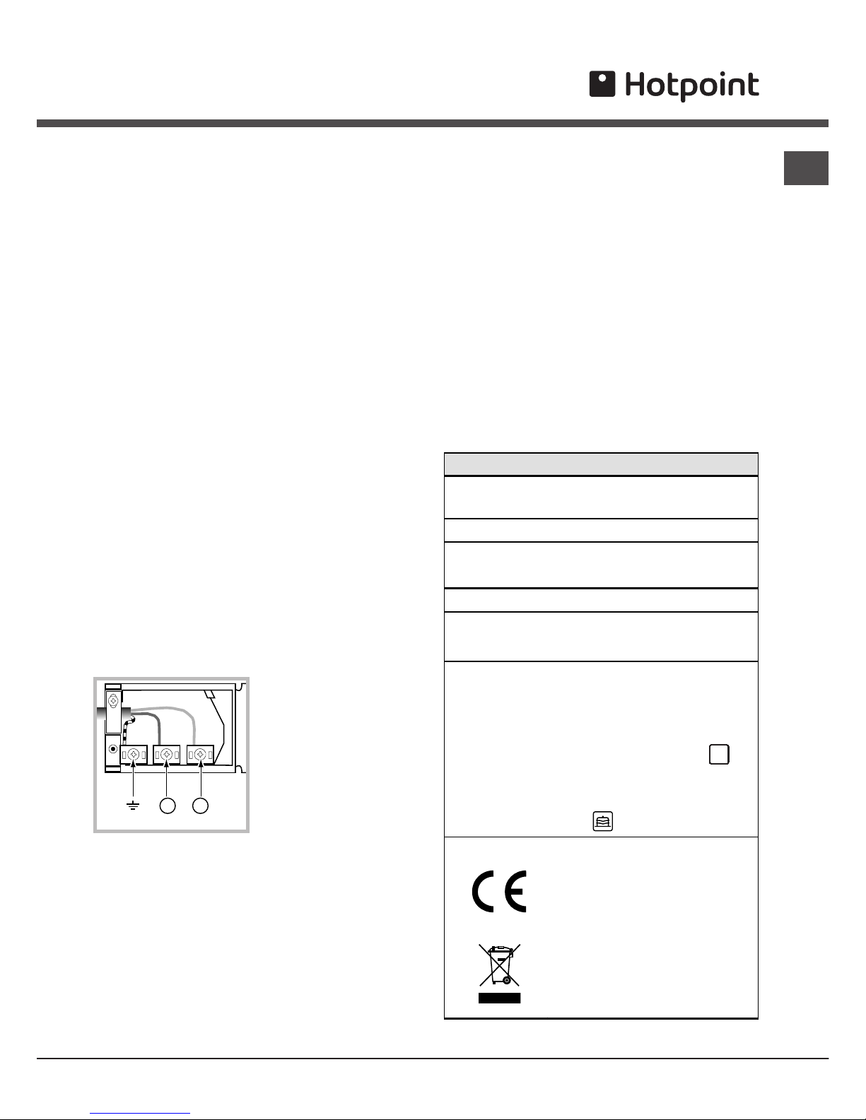
Connecting the power supply cable
To open the terminal board:
• Using a screwdriver, press on the tabs situated
on each side of the terminal board cover.
• Pull open the terminal board cover.
To connect the power supply cable, proceed as
follows:
••
••
• Unscrew the cable clamp screw and the contact
screws L-N-6.
• Fasten the wires beneath the screwheads using
the following colour scheme: Blue (N) Brown (L)
Yellow-Green
6
• Fasten the power supply cable in the
corresponding cable clamp and close the cover.
Electrical Connection:
Voltage Frequency: 230
V-1+N 50Hz
Fuse Section: 16A
Supply cable:
3x1.5mm
2
You can connect your oven to the system means of
a terminal board. Refer to above information for the
minimal cable sections and the calibration of the
protective elements according to the connection.
If the appliance is installed with a junction box, an
omnipolar circuit breaker - with a minimum contact
opening of 3mm - should be installed between the
appliance and the mains.
Power cable supply connection to the electrical
mains:
We recommend you use a power supply cable which
is long enough to allow you to take the oven out of
its recess in the event of maintenance operations
(only use HAR - H 05 - RRF quality cables fitted with
a plug conforming to the regulations in force.
The plug must be accessible at all times.
Unplug the appliance before all operations, even
when replacing the oven lamp.
Using the appliance without correct earthing is
highly dangerous.
! After connecting the appliance to the flexible
cable, tighten all the screws on the terminal
board.
42
NL

4
GB
Control panel
GRILL
DRIPPING PAN
GUIDES for the
sliding racks
position 5
position 4
position 3
position 2
position 1
Description
of the appliance
Overall view
Control panel
Display
SELECTOR
Knob
THERMOSTAT
knob
DISPLAY
TIME SETTING
button
FAST CLEAN
button
TIMER
knob
TEMPERATURE
and TIME digits
END OF COOKING
icon
CLOCK
icon
DURATION
icon
TIMER
icon
STOP
icon
Preheating
indicator
DOOR LOCK
indicator
5
GB
! The first time you use your appliance, heat the
empty oven with its door closed at its maximum
temperature for at least half an hour. Ensure that the
room is well ventilated before switching the oven off
and opening the oven door. The appliance may emit
a slightly unpleasant odour caused by protective
substances used during the manufacturing process
burning away.
Setting the clock
! The clock may be set when the oven is switched
off or when it is switched on, provided that a the end
time of a cooking cycle has not been programmed
previously.
1. Press the
button several times until the
icon and the first two digits on the display start to flash.
2. Turn the TIMER KNOB towards “+” and “-” to
adjust the hour value.
3. Press the
button again until the other two
digits on the DISPLAY begin to flash.
4. Turn the TIMER KNOB towards “+” and “-” to
adjust the minute value.
5. Press the
button again to confirm.
Setting the timer
! This function does not interrupt cooking and does
not affect the oven; it is simply used to activate the
buzzer when the set amount of time has elapsed.
1. Press the
button several times until the
icon and the three digits on the display begin to
flash.
2. Turn the TIMER KNOB towards “+” and “-” to
adjust the minute value.
3. Press the
button again to confirm.
The display will then show the time as it counts
down. When this period of time has elapsed the
buzzer will be activated.
Starting the oven
1. Select the desired cooking mode by turning the
SELECTOR knob.
2. The oven begins its preheating stage and the
preheating indicator lights up.
The temperature may be changed by turning the
THERMOSTAT knob
3. When the preheating indicator
switches off
and a buzzer sounds the preheating process is
complete: you may now place the food in the oven.
4. During cooking it is always possible to:
- change the cooking mode by turning the
SELECTOR knob
- change the temperature by turning the
THERMOSTAT knob
- set the cooking duration in addition to the cooking
end time
(
see Cooking modes
)
- stop cooking by turning the SELECTOR knob to the
“0” position.
5. The oven switches off automatically after two
hours: this default period of time is set for all
cooking modes for safety reasons.
The cooking duration may be changed
(
see Cooking modes
).
6. If a blackout occurs while the oven is already in
operation, an automatic system within the appliance
will reactivate the cooking mode from where it was
interrupted as long as the temperature has not
dropped below a certain level. Programmed cooking
modes which have not started will not be restored
and must be reprogrammed.
!!
!!
! There is no preheating stage for the FAST
COOKING and BARBECUE modes.
!!
!!
! Never put objects directly on the bottom of the
oven; this will avoid the enamel coating being
damaged.
!!
!!
! Always place cookware on the rack(s) provided.
Cooling ventilation
In order to cool down the external temperature of the
oven, a cooling fan blows a stream of air between
the control panel and the oven door. In the FAST
COOKING mode, the fan is activated automatically
after ten minutes. In the BAKING mode, the cooling
fan is only activated when the oven is hot. At the
beginning of the FAST CLEAN mode, the cooling fan
operates at low speed.
!!
!!
! Once cooking has been completed, the cooling fan
continues to operate until the oven has cooled down
sufficiently.
Oven light
When the oven is not in operation, the lamp can be
switched on at any time by opening the oven door.
Start-up and use
 Loading...