

HOTPOINT SH 33 K User Manual
Operating Instructions
OVEN
GB
English,1
SY36B/1
SY36K/1
SY36W/1
SY36X/1
SY37B/1
SY37K/1
Contents
GB
Installation, 2
Positioning
Electrical connection, 3
Data plate
Description of the appliance, 4
Overall view
Control panel
Start-up and use, 5
Starting the oven
The electronic cooking programmer, 6
Cooking modes, 7-8
Cooking modes
Practical cooking advice
Cooking advice table
Precautions and tips, 9-10
General safety
Disposal
Respecting and conserving the environment
SY37W/1
SY37X/1
SH33K
SH33W
SH33X
SHS33X
SHS33XK
SHS33CX
Maintenance and care, 10
Switching the appliance off
Cleaning the appliance
Cleaning the oven door
Replacing the light bulb
After Sales Service, 11
Guarantee, 12
Installation
GB
! Before you operate yuor new Hotpoint Single Oven,
please read these instructions fully. They contain
important information for safe use, for installation and
for care of the appliance.
! Please keep these operating instructions for future
reference. Pass them on to possible new owners of
the appliance.
! Keep packaging material out of the reach of
children. It can become a choking or suffocation
hazard.
see Precautions and tips
).
Positioning
! The appliance must be installed by a qualified
person in compliance with the instructions provided.
Incorrect installation may cause harm to persons,
animals or may damage property.
Fitting the appliance
Use the appropriate cabinet to ensure that the
appliance functions properly.
• The panels adjacent to the oven must be made of
heat-resistant material.
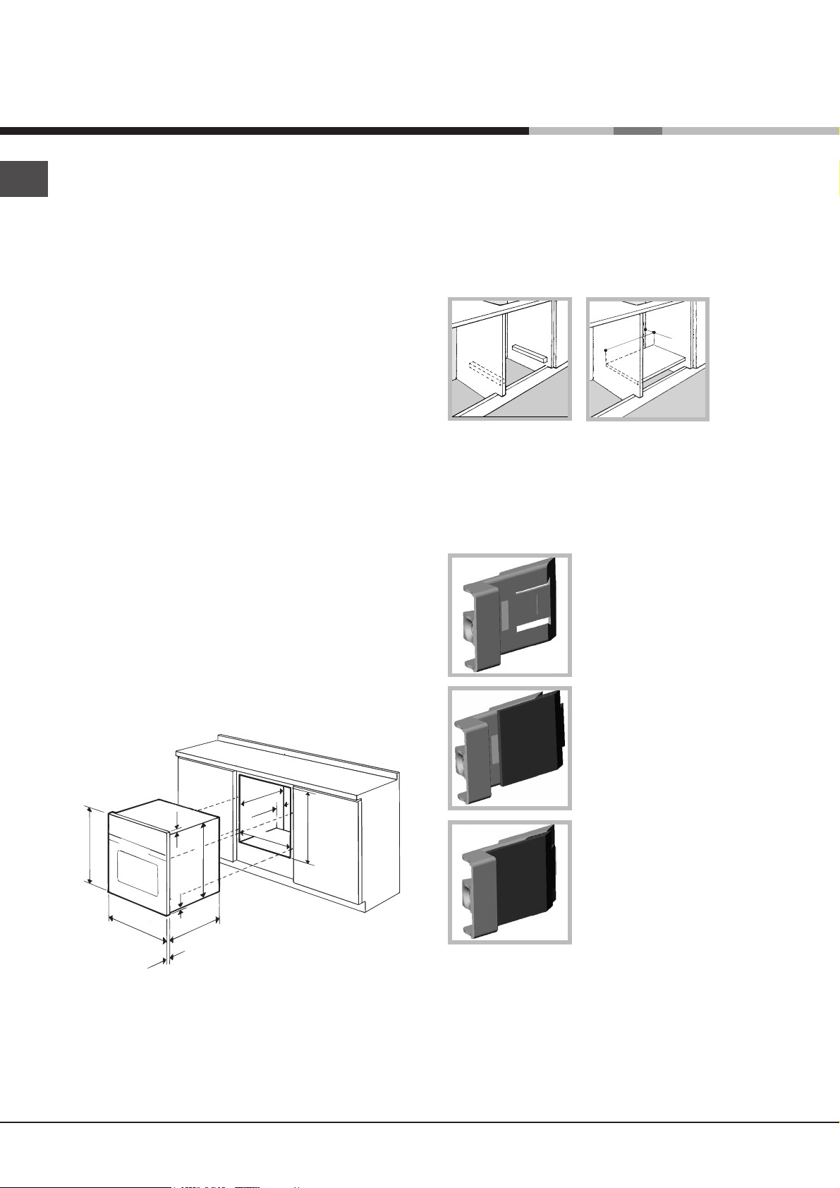
Ventilation
To ensure good ventilation, the back panel of the
cabinet must be removed. It is advisable to install the
oven so that it rests on two strips of wood, or on a
completely flat surface with an opening of at least 45 x
560 mm (
see diagrams
).
45 mm.
560 mm.
Centring and fastening
Position the 4 tabs on the side of the oven according
to the 4 holes of the outer frame. Adjust the tabs
according to the thickness of the cabinet side panel,
as shown below:
thickness of 20 mm: take off
the removable part of the tab
see diagram
(
)
• Cabinets with a veneer exterior must be assembled
with glues which can withstand temperatures of up
to 100°C.
• To install the oven under the counter (
see diagram
and in a kitchen unit, the cabinet must have the
following dimensions:
547 mm. min.
567 mm.
45 mm.
558 mm.
593 mm.
23 mm.
595 mm.
5 mm.
595 mm.
545 mm.
24 mm.
! The appliance must not come into contact with
electrical parts once it has been installed.
The consumption indications on the data plate have
been calculated for this type of installation.
)
thickness of 18 mm: use the
first groove, which has already
been set in the factory (
diagram
)
see
thickness of 16 mm: use the
second groove (
see diagram
)
Secure the appliance to the cabinet by opening the
oven door and putting 4 screws into the 4 holes of the
outer frame.
! All parts which ensure the safe operation of the
appliance must not be removable without the aid of a
tool.
2
Electrical Connection
Electrical connection
The electrical connection to the mains must be made
on the appliance. The power voltage and frequency
are as indicated on the rating plate.
THIS APPLIANCE MUST BE EARTHED.THIS APPLIANCE MUST BE EARTHED.
!
THIS APPLIANCE MUST BE EARTHED.
THIS APPLIANCE MUST BE EARTHED.THIS APPLIANCE MUST BE EARTHED.
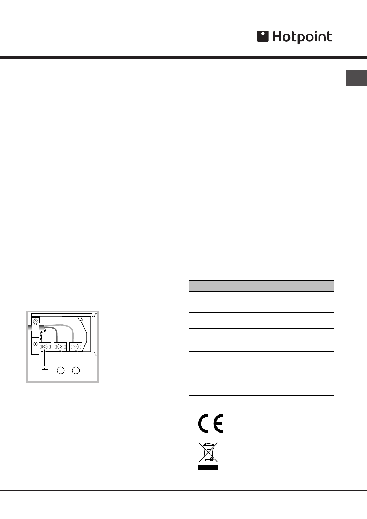
Connecting the power supply cable
To open the terminal board:
• Using a screwdriver, press on the tabs situated on
each side of the terminal board cover.
• Pull open the terminal board cover.
To connect the power supply cable, proceed as
follows:
••
• Unscrew the cable clamp screw and the contact
••
screws L-N-6.
• Fasten the wires beneath the screwheads using the
following colour scheme: Blue (N) Brown (L)
Yellow-Green
6
Power cable supply connection to the electrical
mains:
We recommend you use a power supply cable which
is long enough to allow you to take the oven out of its
recess in the event of maintenance operations (only
use HAR - H 05 - RRF quality cables fitted with a plug
conforming to the regulations in force.
The plug must be accessible at all times.
Unplug the appliance before all operations, even
when replacing the oven lamp.
Using the appliance without correct earthing is
highly dangerous.
! After connecting the appliance to the flexible
cable, tighten all the screws on the terminal board.
GB
• Fasten the power supply cable in the
corresponding cable clamp and close the cover.
Electrical Connection:
Voltage Frequency: 230
V-1+N 50Hz
Fuse Section: 16A
Supply cable: 3x1.5mm
42
NL
You can connect your oven to the system means of a
terminal board. Refer to above information for the
minimal cable sections and the calibration of the
protective elements according to the connection.
If the appliance is installed with a junction box, an
omnipolar circuit breaker - with a minimum contact
opening of 3mm - should be installed between the
appliance and the mains.
DATA PLATE
width cm 43.5
Dim ensions
Vol ume lt. 56
2
Electr ical
connec ti ons
EN ERG Y LABE L
height cm 32
depth cm 40
voltage: 23 0-240V ~ 50Hz
maximum power absorbed
2250W-24 00W
Directive 2002/40/EC on the label
of el ectric ov ens .
Standard EN 50304
Declared energy consumption for
Forced convection Cl ass – hea ting
mode: Fan assisted
This ap pli anc e co nforms to the
followi ng European Economic
Community directives:
- 2 006/ 95/ EEC of 12/12/06 (Low
Vol tage) and subsequent
amendments;
- 2 004/ 108/EEC of 15/12/04
(Electromagnetic Compatibili ty) and
subsequent amendme nts;
- 9 3/68 /EEC of 22/07/93 and
subsequent amendme nts.
- 2 002/ 96/ EC and subseq uent
amendments.
3
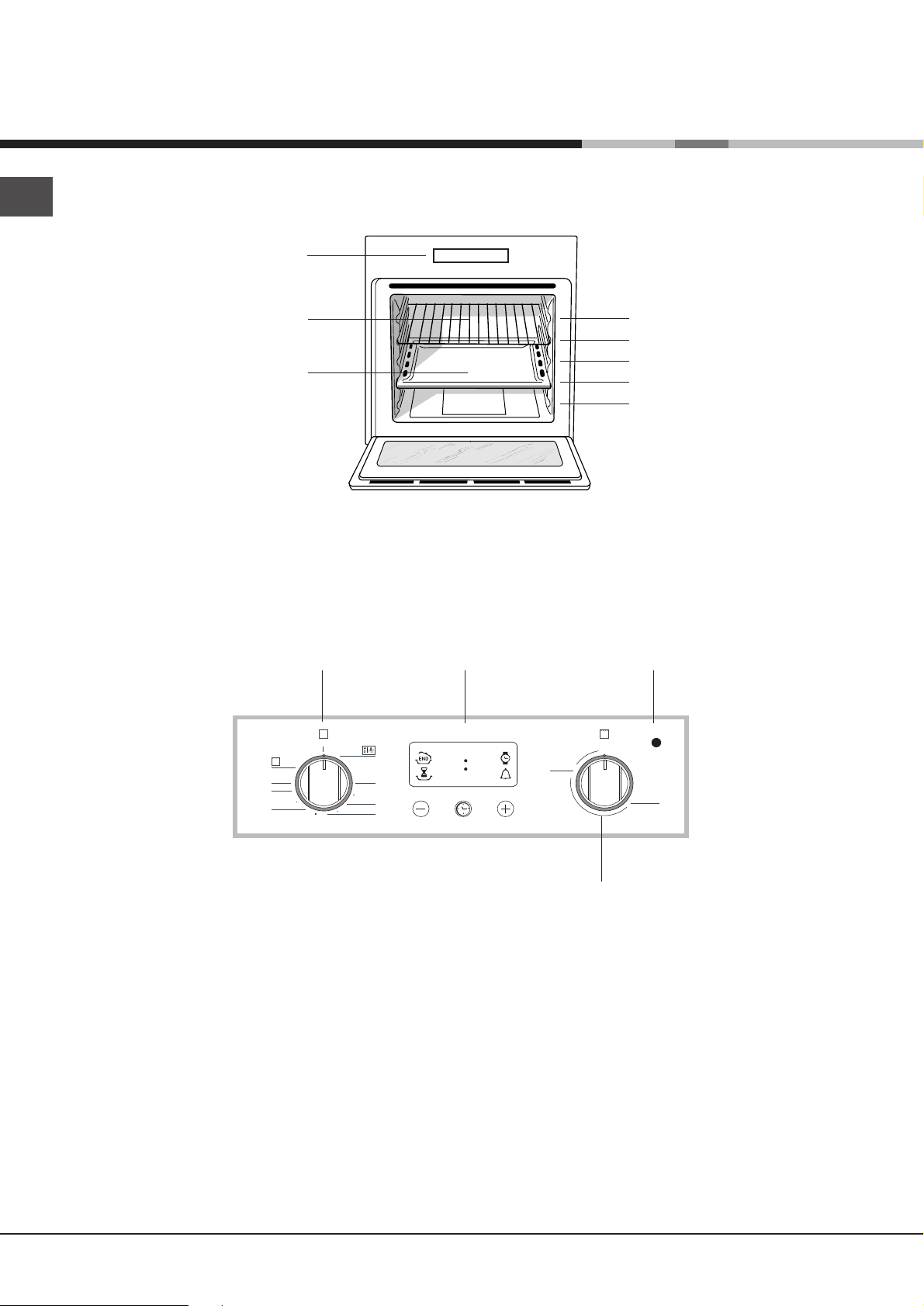
Description of the appliance
GB
Overall view
Control panel
Control panelControl panel
Control panel
Control panelControl panel
GRILLGRILL
GRILL
GRILLGRILL
DRIPPING PANDRIPPING PAN
DRIPPING PAN
DRIPPING PANDRIPPING PAN
GUIDES GUIDES
GUIDES for the
GUIDES GUIDES
sliding racks
position 5position 5
position 5
position 5position 5
position 4position 4
position 4
position 4position 4
position 3position 3
position 3
position 3position 3
position 2position 2
position 2
position 2position 2
position 1position 1
position 1
position 1position 1
SELECTORSELECTOR
SELECTOR
SELECTORSELECTOR
Knob
0
MA
220
180
60
100
140
ELECTRONIC
programmer*
•• ••
Indicator light
THERMOSTATTHERMOSTAT
THERMOSTAT
THERMOSTATTHERMOSTAT
MAX
1/2
MIN
VARIABLE GRILLVARIABLE GRILL
VARIABLE GRILL
VARIABLE GRILLVARIABLE GRILL
Knob
4
 Loading...