

Hotpoint SBS 51 X S User Manual

Please phone us on
08448 24 24 24
to activate your
guarantee
SBS 51 X S
English
Operating Instructions
OVEN
Operating Instructions,1
Warnings,2
Description of the appliance,3
Installation,4
Electrical Connection,5
Start-up and use,6
Modes,6
Precautions and tips,9
Maintenance and care,9
Afetr Sales Service,11
Guarantee,12
Contents

PLEASE PHONE US TO REGISTER YOUR APPLIANCE AND ACTIVATE YOUR PARTS GUARANTEE ON 08448 24 24 24
Warnings
GB
WARNING: The appliance and its
accessible parts become hot during use.
Care should be taken to avoid touching
heating elements. Children less than 8
years of age shall be kept away unless
continuously supervised. This appliance
can be used by children aged from 8 years
and above and persons with reduced
physical, sensory or mental capabilities
or lack of experience and knowledge
if they have been given supervision
or instruction concerning use of the
appliance in a safe way and understand
the hazards involved. Children shall not
play with the appliance. Cleaning and
user maintenance shall not be made by
children without supervision.
Do not use harsh abrasive cleaners or
sharp metal scrapers to clean the oven door
glass since they can scratch the surface,
which may result in shattering of the glass.
Never use steam cleaners or pressure
cleaners on the appliance.
WARNING: Ensure that the appliance is
switched off before replacing the lamp to
avoid the possibility of electric shock.
! When you place the rack inside, make
sure that the stop is directed upwards and
in the back of the cavity.
2
PLEASE PHONE US TO REGISTER YOUR APPLIANCE AND ACTIVATE YOUR PARTS GUARANTEE ON 08448 24 24 24
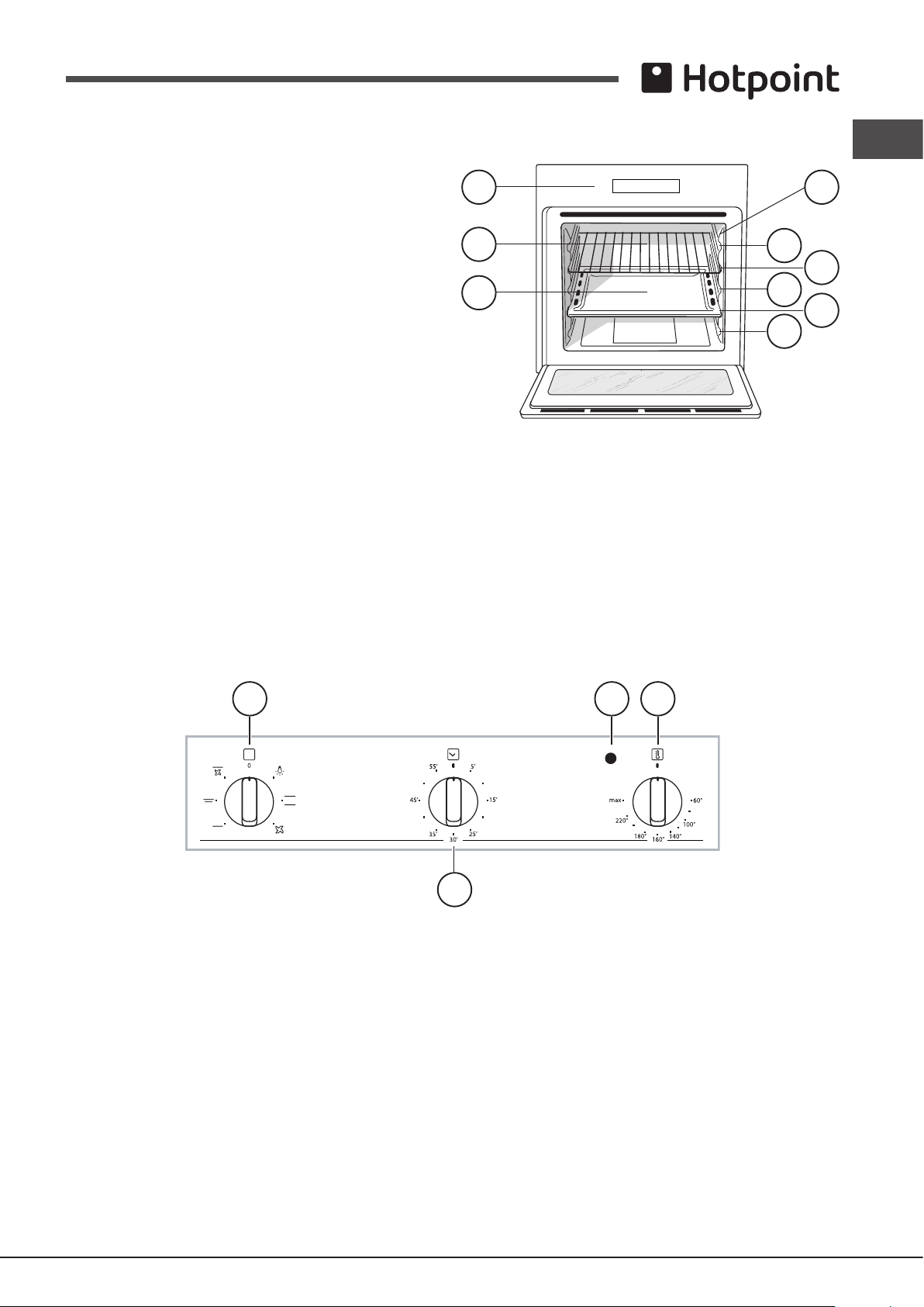
Description of the appliance
7
1
3
451
2
Overall view
1. POSITION 1
2. POSITION 2
3. POSITION 3
4. POSITION 4
5. POSITION 5
6. GUIDES for the sliding racks
7. DRIPPING PAN
8. GRILL
9. Control panel
Control panel
1. SELECTOR Knob
2. TIMER Knob*
3. THERMOSTAT Knob
4. Indicator light THERMOSTAT
GB
9 6
8
2
4
3
* Only available in certain models.
3
PLEASE PHONE US TO REGISTER YOUR APPLIANCE AND ACTIVATE YOUR PARTS GUARANTEE ON 08448 24 24 24
Installation
590 mm.
GB
! Please keep this instruction booklet in a safe place for
future reference. If the appliance is sold, given away or
moved, please make sure the booklet is also passed on to
the new owners so that they may benet from the advice
contained within it.
Ventilation
To ensure adequate ventilation, the back panel of the
cabinet must be removed. It is advisable to install the oven
so that it rests on two strips of wood, or on a completely
at surface with an opening of at least 45 x 560 mm (see
diagrams).
! Please read this instruction manual carefully: it contains
important information concerning the safe operation,
installation and maintenance of the appliance.
Positioning
! Do not let children play with the packaging material; it
should be disposed of in accordance with local separated
waste collection standards (see Precautions and tips).
! The appliance must be installed by a qualied professional
in accordance with the instructions provided. Incorrect
installation may damage property or cause harm to people
or animals.
Built-in appliances
Use an appropriate cabinet to ensure that the appliance
operates properly:
• The panels adjacent to the oven must be made of heatresistant material.
• Cabinets with a veneer exterior must be assembled with
glues which can withstand temperatures of up to 100°C.
• To install the oven under the counter (see diagram) or
in a kitchen unit, the cabinet must have the following
dimensions:
45 mm.
560 mm.
Centring and xing
Secure the appliance to the cabinet:
• Open the oven door.
• Remove the 4 rubber plugs covering the xing holes on
the perimeter frame.
• Fix the oven to the cabinet using the 4 wood screws.
• Replace the rubber plugs.
! All parts which ensure the safe operation of the appliance
must not be removable without the aid of a tool.
550 mm.
min.
45 mm.
560 mm.
575-585 mm.
570 mm.
595 mm.
20 mm.
550 mm.
20,5 mm.
22,5 mm.*
* Stainless steel models only
! The appliance must not come into contact with electrical
parts once it has been installed.
The indications for consumption given on the data plate
have been calculated for this type of installation.
4
 Loading...