

Hotpoint RGB518PCHWH Conversion Kit
L.P. CONVERSION
INSTRUCTIONS
WARNING:
This conversion must be performed
by a qualified installer or gas supplier
in accordance with the
manufacturer’s instructions and all
codes and requirements of the
authority having jurisdiction. Failure
to follow ALL instructions could result
in serious injury or property
damage. The qualified agency
performing this work assumes
responsibility for the conversion.
The pressure regulator and the burner
orifices are set for natural gas. To use
Liquid Propane Gas, the regulator,
burner orifices and thermostat pins
must be converted. The L.P. orifices for
the cooktop burners and pins for the
thermostat are shipped in a paper
envelope on the back of the range.
WARNING:
Do not operate the cooktop or oven
burners of this range when using L.P.
(bottled) gas before converting the
pressure regulator and burner orifices
for L.P. gas use. Failure to do so could
cause high flames and toxic fumes
which can result in serious injury.
To adjust your range for use with L.P. gas,
follow these instructions:
1. Remove battery from battery case.
2. Shut off the gas supply to the range by
closing the manual shut-off valve.
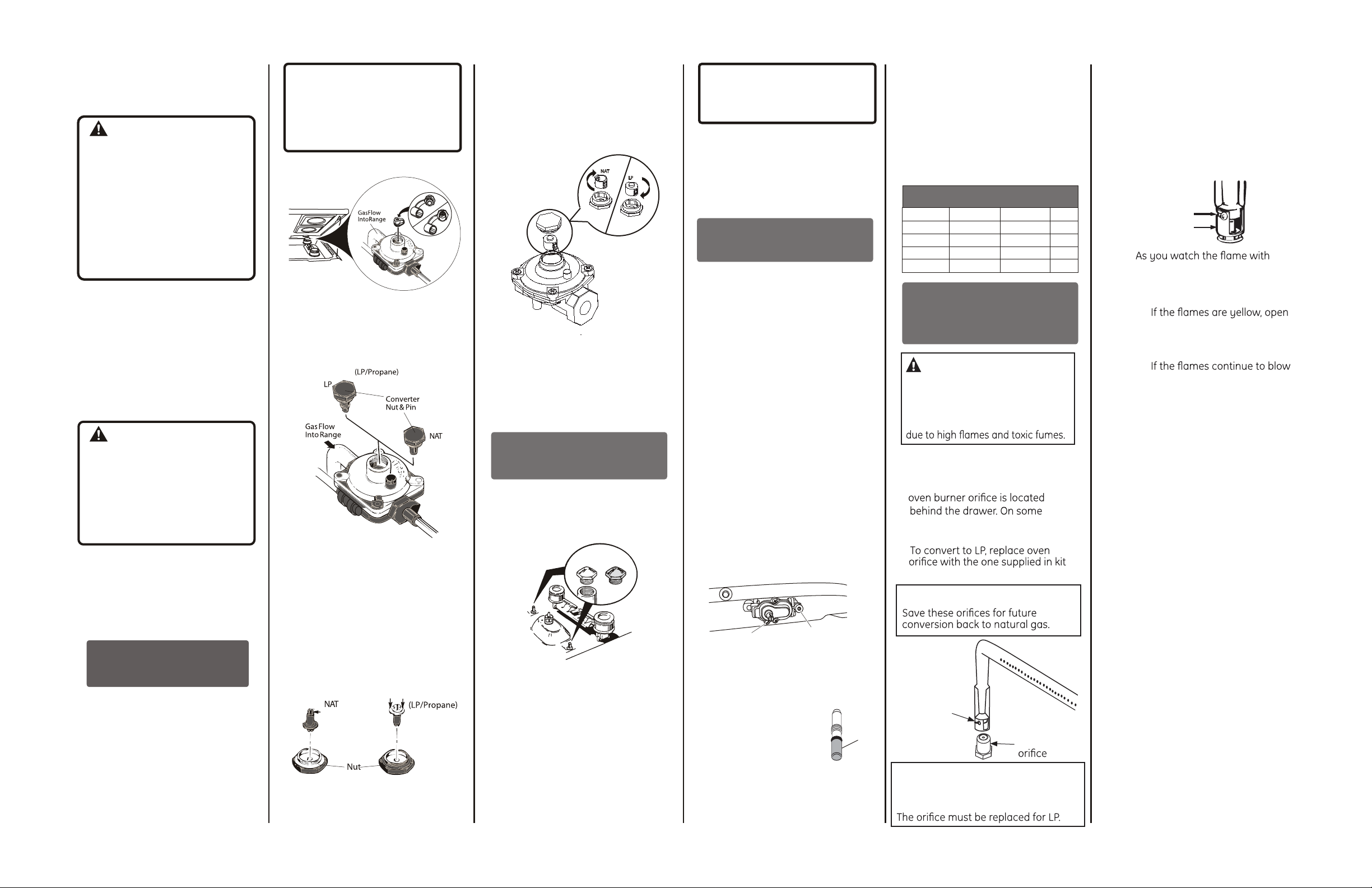
CONVERTING THE
PRESSURE REGULATOR
a. Raise the cooktop and locate the
pressure regulator.
b. Follow the direction in 1A or 1B
depending on your regulator
type.
NOTICE:
If you are using L.P. (bottled) gas, all
adjustments described inthe
following steps must be made before
you make any burner adjustments.
Regulator pictured may be different
from your model.
1A-IF THIS IS YOUR REGULATOR
a. Use an adjustable wrench to
remove the hex-nut from the
pressure regulator.
b. Apply sideward finger pressure to
remove the plastic pin from the
nut.
Note: To remove the pin, place
the nut on a flat surface and
press the pin sideways with your
fingers.
c. Rotate the pin 180 degrees and
snap the pin back into the nut.
d. Reinsert the assembly into the
regulator and tighten the hex-nut.
(Do nor over tighten)
1B-IF THIS IS YOUR REGULATOR
a. Use an adjustable wrench to
unscrew the hex-nut cap from
the pressure regulator.
b. Apply pressure and turn counter
clockwise to disassemble the
plastic cap.
NAT
LP
c. Turn the cap over and hook it into
the slots. The type of gas to be
used should now be visible in the
top of the cap.
d. Screw back the hex-nut cap into
the pressure regulator.
CONVERTING THE
COOKTOP BURNERS
a. Lift the burner assemblies
straight up (set aside) to gain
access to the surface burner
orifice spuds.
Natural Gas
b. Using a 5/16” (8 mm) nut driver or
adjustable wrench, remove each
of the four (4) spuds on the
surface burner gas inlet tubes.
c. Replace them with the correct
gas spuds shipped in a paper
envelope on the back of the
range. To prevent leakage, make
sure the spuds are securely
screwed into the gas inlet tubes).
(Natural gas spuds are “BRASS”
and LP gas spuds are “SILVER”)
Brass
LP Gas
Silver
OR
NOTICE:
Save these orifices for future
conversion back to natural gas.
d. Return the spuds you removed
from the inlet tubes to the paper
envelope.
e. Replace the burner assemblies.
CONVERTING THE OVEN
THERMOSTAT
a. Remove all five (5) knobs,
including OVEN CONTROL knob.
Remove the two (2) screws
located behind the two (2) inner
cooktop knobs.
b. Open the oven door. Remove the
three (3) screws located under
the mainfold panel. Remove the
mainfold panel.
c. Locate the thermostat bypass
screw below the thermostat
shaft.Completely loosen the
natural gas bypass screw (blue)
by turning it counterclockwise.
Remove it by gently pulling it out
using pliers.
d. Replace with the LP bypass screw
(white/green) located in the paper
envelope on the back of the
range. Tighten the screw by
turning it clockwise.
Turn Screws Counter clockwise to
loosen
Bypass
Screw
e. Locate the thermostat pilot
flame screw to the right of the
thermostat shaft.
Completely
loosen the natural
gas pilot screw (pink)
by turning it
counterclockwise
Remove it by gently
pulling it out using
Pliers.
Pilot
Flame
Screw
LP or Nat
Bypass and Pilot
Flame screws look
similar, please see
chart below for
correct screw
Color
Indication
f. Replace with the LP pilot screw
(black) located in the paper
envelope on the back of the
range.
Tighten the screw by turning it
clockwise.
g. Replace manifold panel and
knobs.
Bypass and Pilot Flame Screws
GAS TYPE SCREW TYPE COLOR SIZE
Natural Gas
Natural Gas
LP (Propane)
LP (Propane)
Bypass
Pilot
Bypass
Pilot
Blue # 76
Orange
Brown
Violet
CONVERTING
THE OVEN BURNERS
(on gas oven models only)
WARNING
The following adjustments must be
made before turning on the gas
to the oven burner. Failure to do so
could result in serious injury
OVEN BURNER ORIFICE
1. Remove oven door, broil drawer,
oven bottom, and burner. The
models a metal shield must be
removed.
2.
with range.
NOTICE:
Oven burner
air shutter
Oven
NOTICE:
This product cannot be converted to
LP by adjusting the oven orifice.
# 30
# 53
# 18
AIR SHUTTER SETTING FOR
OVEN BURNER
1. Turn on the gas.
2. Assemble battery in battery case
(check polarity).
3. Replace the oven bottom and
reinstall the oven door.
4. Turn on the oven burner.
Screw
Air shutter
5.
the oven door closed, check the
following through the broil drawer
opening.
a.
the air shutter more. Use a
screwdriver to loosen the air
shutter screw.
b.
away or flutter from the burner
after two minutes of operation,
close the air shutter slightly,
but not by more than 1/8”.
6. Retighten the air shutter screw.
Pub. No. 31-10928-3
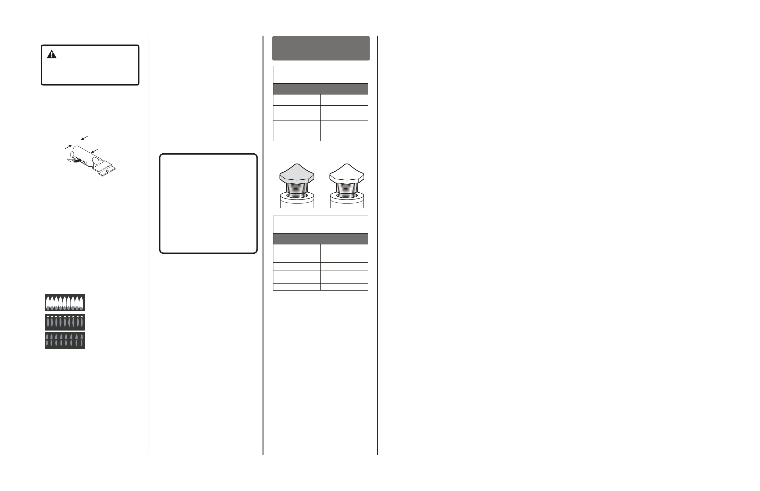
CHECKING THE FLAME SIZE
WARNING:
If you attempt to measure
the inner cone of the flame, please
use caution; burns could result.
1. Checking the flame size:
Check the inner cone of the flame.
It should be approximately ½” to
¾” long for the bake and broil
burners.
INNER CONE
OF FLAME
1/2" to 3/4"
OVEN BROILER
BURNER
CHECKING THE FLAME QUALITY
The combustion quality of the
burner flames need to be
determined visually.
NOTE: If burner flames look like
(A). Further air shutter adjustmentis required. Normal burner
flames should look like (B) or (C),
depending on the type of gas
you use. With LP gas, some
yellow tipping on the outer
cones is normal.
(A) Yellow Flames:
Further Adjustment
Required
(B) Yellow tips on
outer cones:
Normal for LP Gas
(C) Soft Blue Flames:
Normal for Natural Gas.
When all adjustments are made
and the results are satisfactory:
a. Replace the orifice fitting cover
(in some models).
b. Replace the oven bottom.
IN SOME CASES:
a. With L.P. gas, some yellow
tipping on the outer cone is
normal.
b. Foreign particles in the gas line
may cause an orange flame at
first, but this will soon disappear.
SPECIAL NOTE:
To convert the oven back to natural
gas, reverse the instructions given in
making L.P. Adjustments.
REPLACE OVEN PARTS
Replace the oven bottom, oven racks,
oven door and broil drawer.
NOTICE:
Once the conversion is complete and
checked ok, fill out the L.P. Sticker
and include your name, organization
and date conversion was made.
Apply the sticker to the range near
the regulator to alert others in the
future that this appliance has been
converted to L.P. If converting back
to natural gas from L.P., please
remove the sticker so others know
the appliance is set to use natural
gas.
ADDITIONAL
INFORMATION
BURNER OUTPUT RATINGS:
BTU/HR
LP (Propane) Gas, 10” W.C.P.
BURNER
RF
LF
LR
RR
BAKE
BTU
RATE
8,000
8,000
8,000
8,000
16,500
LP GAS
Spud is Silver
BURNER OUTPUT RATINGS:
BTU/HR
NG (Natural) Gas, 4” W.C.P.
BURNER
RF
LF
LR
RR
BAKE
BTU
RATE
9,100
9,100
9,100
9,100
18,000
TOOLS REQUIRED:
Adjustable wrench
½” open-end wrench
Phillips head screwdriver
Flat bladed screwdriver (blade
width approximately 3/32”
across)
Nut drivers: 5/16", 1/4" or 8mm
ORIFICE SIZE
#66 (.0330 Dia.)
#66 (.0330 Dia.)
#66 (.0330 Dia.)
#66 (.0330 Dia.)
0.048”
NATURAL GAS
Spud is Brass
OR
COLOR
#53 (.0590 Dia.)
#53 (.0590 Dia.)
#53 (.0590 Dia.)
#53 (.0590 Dia.)
0.083” (2.11)
L.P. CONVERSION
INSTRUCTIONS
RGB518, JGBS14
Pub. No. 31-10928-3
04-14 GE
 Loading...