

Hotpoint 64003, Re963009, Re963004 Owner's Manual
- 1 -
Height
3" Min.
Width
Depth
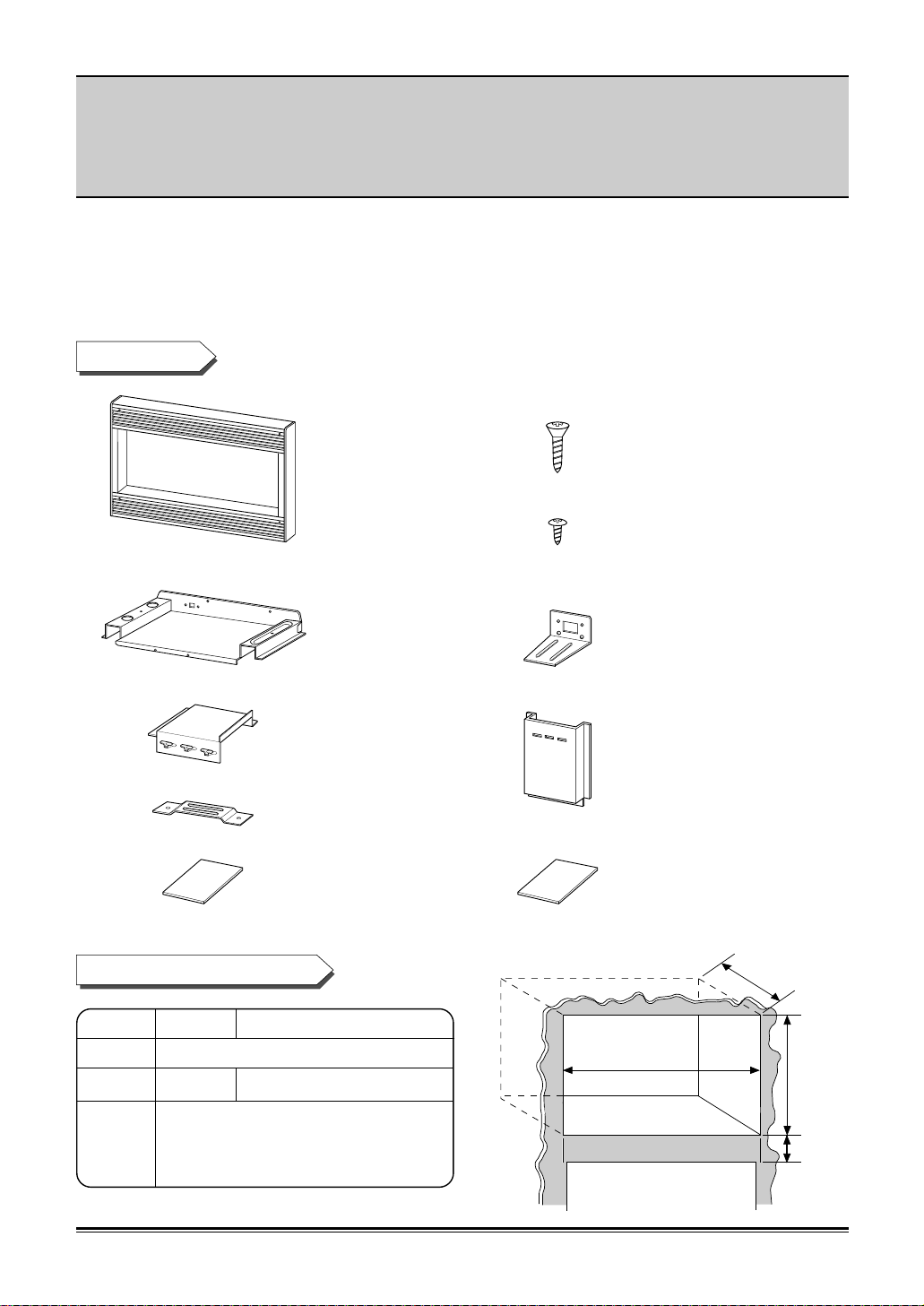
BUILT-IN TRIM KIT INSTALLATION INSTRUCTION
FOR KENMORE TRIM-KIT MODEL - 30” : 63002, 63004, 63009, 64003
27” : 63012, 63014, 63019, 63013
■
FOR USE WITH KENMORE MICROWAVE OVEN MODEL:
721.62462200, 721.62463200, 721.62464200, 721.62469200, 721.66462500, 721.66463500, 721.66464500. 721.66469500
■
UL LISTED - FOR USE OVER KENMORE 30”,27” ELECTRIC BUILT-IN OVENS
(INCLUDING MODELS - 30” : 41785, 41789, 41085, 41086, 41089, 49002, 49003, 49004, 49009
27” : 47489, 47485, 47486, 47189)
P/NO.: 3828W5U0189
• Trim Kit
• Bottom Duct (1)
•
Upper Duct (1)
•
Anti-Tip
Bracket (1)
• Installation
instruction (1)
•
1” Screws
(4 Req’d 2 Extra)
•
1
/2” Screws
(11 Req’d 2 Extra)
•
Bottom Bracket (1)
• Side Duct (1)
•
Template (1)
PARTS LIST
CUTOUT DIMENSIONS
Height 16
3
/4”
Width
25
1
/2” 25 1/2” (min.), 28 1/2” (max.)
Depth 21“ with flush mount receptacle.
(min.) (22
3
/4” if non-flush receptacle is
used)
27” 30”

- 2 -
1
/2" Screws (2)
Front
Rear
1
/2" Screws (2)
1
/2" Screws (2)
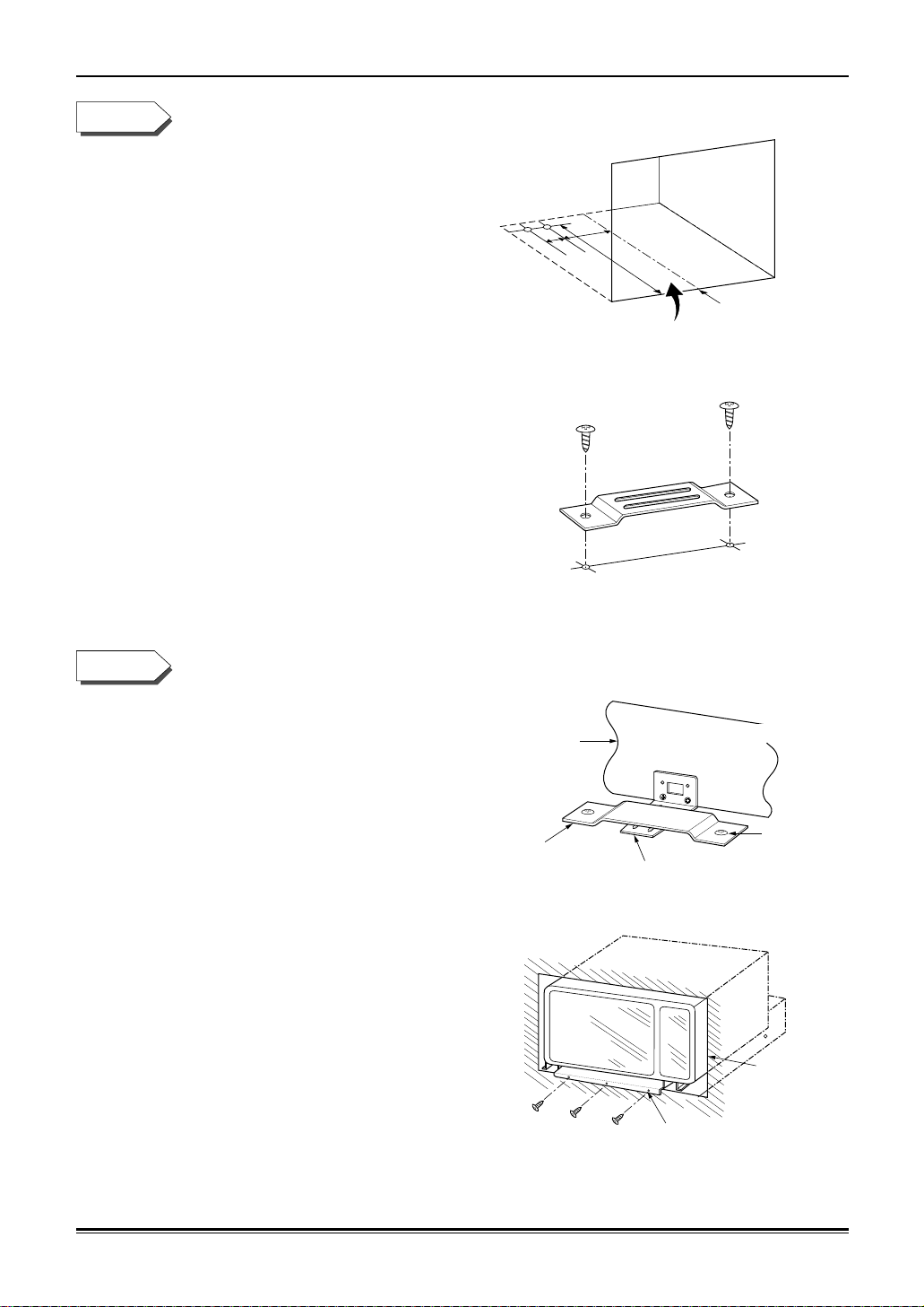
1. Disconnect the microwave oven from the
outlet before proceeding with installation.
2. Remove any loose items (turntable, support,
etc) from the microwave oven.
3. Fasten the bottom bracket to the bottom duct
by using two
1
/2” screws.
4. Install bottom duct with four
1
/2” screws as
shown.
FRONT VIEW OF
MICROWAVE
1. Remove the one existing screw from the left side of the microwave oven.
2. Connect the side duct to upper duct as shown.
a) Insert projecting tabs of upper duct into holes of side duct.
b) Bend tabs up as shown.
NOTE: Remove any oil or dirt on surface of microwave oven before ducts are attached.
3. Peel off the backing of double sided tape.
Attach the side duct and upper duct assembly
on the microwave cabinet. Press down firmly
on ducts. Fasten duct assembly to left side of
cabinet with one existing screw.
Upper Duct
3 tabs
Side Duct
3 Holes
"a)"
"b)"
Existing
Screw (1)
STEP 1
STEP 2
- 3 -
1. Slide microwave oven part way into cabinet
opening.
(Bottom brackets must be flat to the cutout
floor to engage correctly with anti-tip
brackets as shown)
2. Plug in the microwave oven.
3. Center the microwave oven within the
cut-out opening and slide the microwave
oven in the anti-tip bracket.
(Ensure the microwave oven is accurately
centered)
4. Drill pilot holes (use
7
/64” drill or #35 drill)
through the positioning flange and then
install three
1
/2” screws at the front of the
bottom duct as shown.
Bottom Duct
Anti-Tip
Bracket
Bottom Bracket
1
/2" Screw
Anti-Tip Assembly
Positioning
Flange
Cutout
Opening
1
/2" Screw
1. On the cutout floor, mark hole centers for the
anti-tip brackets as shown using the supplied
template. Be sure to align the center line of
template to center line of cutout floor.
2. Drill two holes for anti-tip bracket.
(use
7
/64” drill or #35 drill)
3. Install anti-tip bracket onto cutout floor using
two
1
/2” screws.
DIMENSIONS:
A = 4
1
/4”
B = 3”
C = 18
3
/16”
A
B
C
Cutout Floor
Center Line
Anti-Tip Bracket
1
/2" Screws (2)
STEP 3
STEP 4
 Loading...