

Page 1
PZ 640T GH NG and PZ 750R GH NG
Operating, Care and
Installation Instructions
Contents
Safety Warnings 2
Using Your Cooker 3
Installation 4-5
Service Details 6
Troubleshooting 7
Care And Maintenance 8
Installer - Ensure these instructions remain with the consumer.
This cooktop has been certifi ed for use by SAI-Global
Page 2
Safety Warnings
This appliance has been designed and manufactured
in compliance with Australian and international safety
standards. The following warnings are provided for safety
reasons and must be read carefully.
DO NOT SPRAY AEROSOLS IN THE VICINITY OF THIS
APPLIANCE WHILE IT IS IN OPERATION.
DO NOT MODIFY THIS APPLIANCE.
DO NOT USE OR STORE FLAMMABLE MATERIALS
NEAR THIS APPLIANCE.
This appliance is not suitable for marine craft, caravans or
recreational vehicles
This appliance is not intended to be used by young children, the elderly or infi rm without supervision.
Young children should be supervised at all times when
near this appliance.
If the appliance fails to operate correctly, contact place of
purchase or their appointed agent for advice and service.
Do not touch hot surfaces. Allow hob to cool before wiping
spillage.
There are no user serviceable parts within this appliance.
For any service, contact the place of purchase or the
nominated service agent. Do not attempt repairs yourself.
The appliance was designed for domestic use inside the
home and is not intended for commercial or industrial use.
The appliance must not be installed outdoors, even in
covered areas. It is extremely dangerous to leave the appliance exposed to weather.
Always make sure the knobs are in the OFF position when
the appliance is not in use.
Always make sure that pan handles are turned towards
the centre of the hob in order to avoid accidental burns.
Gas appliances require a regular air supply to maintain
effi cient operation. Always ensure that the kitchen is ad-
equately ventilated whilst the appliance is in use.
Never leave cooking food unattended. Do not allow the
liquid to boil dry
Do not use asbestos mats or heat diffusers, as these
trap the heat and can cause damage to the cooktop from
overheating.
Don’t wear loose clothing while cooking, as garments may
catch utensil handles or catch fi re.
Use dry utensil holders. Wet pot holders can build up
steam. Do not use towels or other large pieces of cloth to
pick up cooking utensils, as these may touch the heating
element and catch fi re.
Do not allow pot handles to overhang other burners that
are in use, as this will cause scorching of the handle, and
potential handling burns.
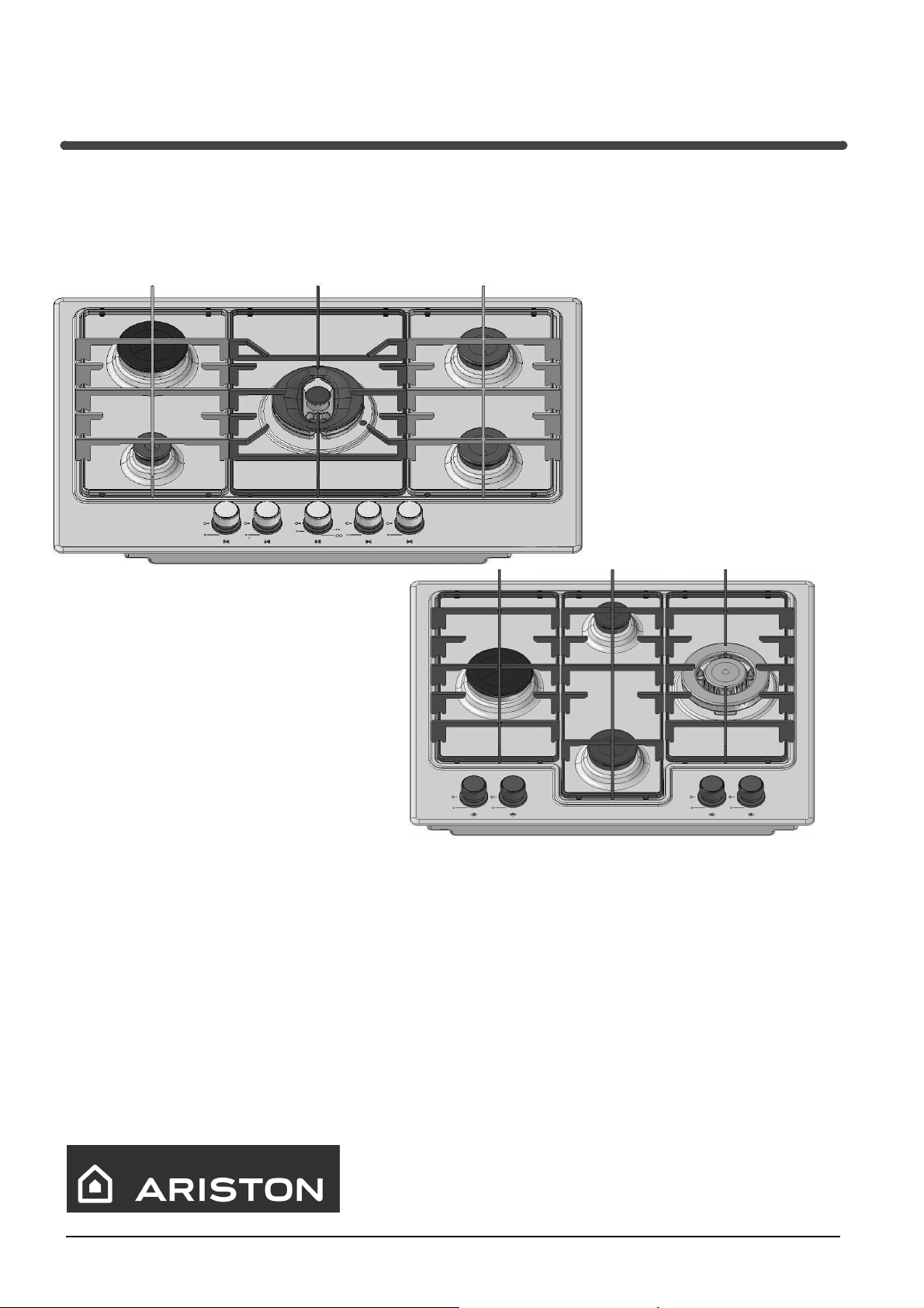
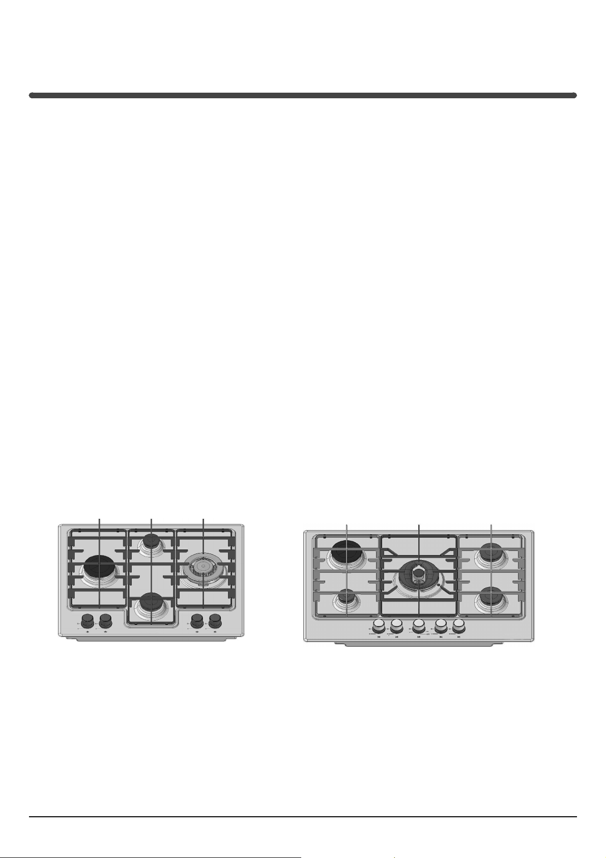
Rapid
Burner
Auxiliary
Burner
Semi Rapid
Burner
Wok
Burner
Rapid
Burner
Auxiliary
Burner
Double Crown
Double Ring
Burner
Semi Rapid
Burner
Semi Rapid
Burner
2
Page 3
Using Your Cooker
Controlling the burners
Each control knob is marked to indicate which burner it
controls. Each control knob also has markings to indicate the
three main settings:
OFF
High
Low
Lighting the burners
Your Arisit hobs are equipped with a safety probe that prevents the gas from fl owing unless there is a fl ame.
To ignite a burner, press and turn the control knob counterclockwise until the knob points to High. Keep pressing the
knob inwards until the probe heats up. Release the knob.
safety probe
ignitor
Check that the gas has been lit. If the burner fails to ignite try
again. If the burner fails to ignite after 3 attempts, wait a few
minutes for the gas to disperse before making any further
attempts.
If the burner still fails to ignite, a match or lighting device can
be used, but care must be taken. If the problem persists, contact place of purchase or their appointed agent for service.
Lighting the burners for the fi rst time
If the appliance is being used for the fi rst time, or if it has not
been used for a long period of time, it may be necessary to
purge the gas lines of excess air before you can successfully
light the burners.
To do this, turn each burner to high for 10-15 seconds and
press the ignition button several times. If the burner does not
light, repeat this procedure twice more. Wait 1-2 minutes for
any gas build up to disperse before allowing any further gas
fl ow.
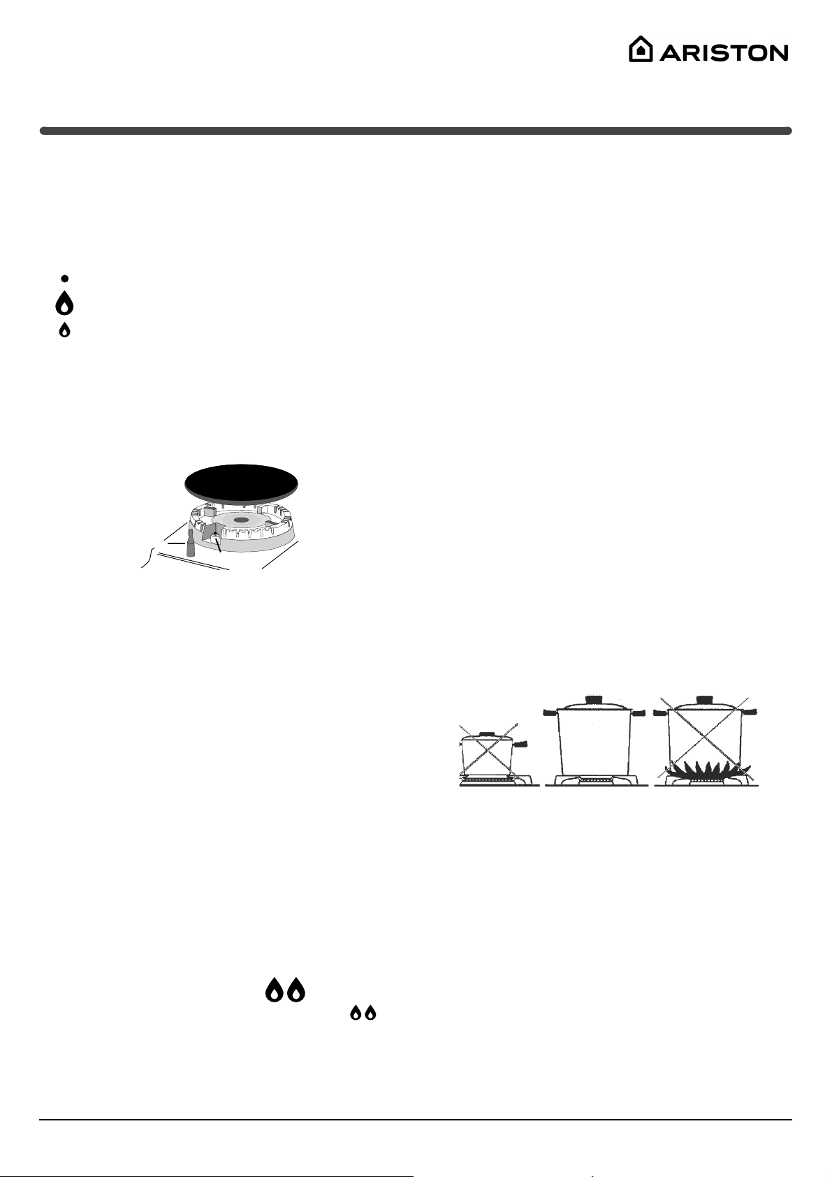
Cookware
Use appropriate cookware for each burner
Always use a vessel for cooking that is appropriate in size
for the size of burner. Ensure the fl ames do not extend
beyond the bottom of the pot.
Never use pots that are too small or too large. For wok
cooking it is recommended that a domestic size wok, no
larger than 400 mm in diameter be used.
Always use cookware with a fl at base. Do not use pans
which are unstable or which have a warped or damaged
base.
Ensure the pot sits securely on the trivet and is centred
above the burner.
Small pots can be used on the inner ring of the double
crown double ring burner.
Controlling the fl ame height
Any fl ame height can be achieved between High and Low by
rotating the control knob between the two positions:
Avoid operating the burner with the control knob set between
Off and High.
If a fl ame is accidentally extinguished, turn off the control
knob and wait for at least 1 minute before relighting.
Double Crown Double Ring Burner (PZ750
only)
Double ring burners have two independent gas rings controlled by the one control knob. Turning the knob anticlockwise
from the Off position controls the smaller inner ring only.
To switch on the outer ring, keep turning the knob anticlockwise past the 6 O’Clock position. The outer ring will ignite
as well, and both rings will be on High
rotate the knob until both rings are operating on Low
.. Continue to
..
To turn off the burner
To switch off the burner, turn the knob in a clockwise direction
until it reaches the 0ff position.
3
Page 4

Installation
WARNING: Before installation, check that the gas type (natu-
ral gas or LPG/Propane) of the cooker is suitable for the gas
type available to the installation. It is extremely dangerous to
use the wrong gas type with any appliance, as fi re or serious
injury can result.
These instructions have been prepared for use by authorised
persons. This unit must only be installed by an authorised
person.
This appliance must not be installed in marine craft or recreational vehicles.
Compliance with standards
This cooktop must be installed in accordance with the requirements of local gas and electrical authorities, as well as
the latest published versions of the following standards:
AS/NZS 5601 Gas Installation code
SAA Wiring Rules
Dimensions of cutout
The following diagram indicates the dimensions of the required cutout.
In placing the cooktop, suitable insulation between the cooktop undersurface and the top of the bench should be used.
Wherever possible, the cooktop should be secured to the
benchtop using clamps.
Fitting the cooktop into cabinetry
The following minimum clearances to combustible materials
must be observed:
Minimum clearance from edge of burner to side wall must
be 200 mm.
Minimum clearance from edge of burner to rear wall must
be 200 mm.
Minimum clearance from top of highest burner to cupboard
above hob burners must be 600 mm.
555 mm
55 mm
475 mm
INSTALLER: Please also ensure that the duplicate data label
supplied, be affi xed in a suitable easily accessible location
such as an adjacent cupboard or drawer, for future reference.
Dimensions (mm) PZ640 PZ750
length (side to side) 600 750
width (front to back) 510 510
depth 44 44
Fixing to the housing unit
Proceed with fi xing to the housing unit as follows (see fi gure
above).
Mount the hooks, partly tightening the screws into the
holes.
Position the sealing gasket approximately 5-6 mm from
the edge of the installation hole, matching up the two ends
of the seal without overlapping.
Insert the hob into the cutout, making sure it is positioned
centrally and that the edge adheres to the sealant
Position the hooks correctly, as shown in the fi gure, and
then tighten the screws to hold them in place.
Range hoods
Range hoods and overhead exhaust fans must be installed
according to manufacturers’ instructions but in no case shall
clearance from hob burners be less than 600 mm for range
hoods and 750 mm for overhead exhaust fans.
Adjacent cabinetry
It is recommended that the adjacent kitchen surfaces should
be capable of withstanding temperatures of 100°C.
4
Page 5

Installation
Fitting the cooktop above an oven
When installing the cooktop above an oven, both the electricity supply cable and the gas pipe or fl exible hose must not
touch hot parts of the oven housing.
When installing above a built-under oven without forced cooling ventilation, suitable air vents should be provided for as
shown in the fi gure (inlet at least 200 cm² from the bottom,
outlet at least 120 cm²
from the top part) to
allow adequate ventilation inside the housing
unit.
Also a wooden panel
“A” should be installed
beneath the hob as insulation, positioning it
at a minimum distance
of 15 mm from the hob
housing
200 cm²
Gas connection
Electrical connection
The electrical supply for the cooktop must be a 240 Volt 50
Hz.
The fuse and electrical wiring of the home/premises must
support the load of the appliance.
The appliance must be earthed. A 3 pin fl exible power cord
is supplied with the appliance to allow the cooktop to be
connected to a properly earthed and rated power socket.
The fl exible cord of the appliance must not be subject to
direct heat and must be positioned after installation of the
appliance so that its temperature does not exceed 75°C.
IMPORTANT If a power socket needs to be installed or
relocated, the work must be done by a licensed electrician.
Gas type conversion
If the hob is to be converted for use with a type of gas other
than that for which it was set in the factory (indicated on the
cooktop data plate), the burner injectors must be replaced as
follows:
Remove the pan supports and the burners.
Unscrew the injectors (“A” in fi ugure below) using a 7 mm
socket wrench, and replace them with injectors of suitable
orifi ce diameter, as indicated on the appliance data plate.
Reassemble the parts.
This appliance is suitable for use with either a fl exible con-
nection or rigid copper connection. If installing the appliance
with a fl exible connection, the fl exible connection must be
approved to class B or D of AS/NZS1869 as a minimum.
Fit regulator supplied for Natural Gas (if applicable) at rear
of appliance, and as close as practicable to the appliance.
It is recommended that an isolating valve and union be
fi tted, to enable simple disconnection for servicing. These
are to be in an accessible location.
Flexible hose
If a fl exible hose is used, it should be as short as possible
with a maximum length of 1.5 metres;
it should not be bent or kinked;
it should not be in contact with the rear wall of the appliance or in any case with parts which may reach a temperature of 50°C;
it should not come into contact with pointed parts or sharp
corners;
it should be easy to inspect along its entire length in order
to be able to check its condition.
The supply connection point must be accessible with the
appliance installed.
If a regulator is required for the new gas type, instal an ap-
proved regulator of appropriate pressure setting and fl ow
capacity.
Replace the gas type label with one suitable for the new
gas type.
Perform the post installation checks as described later in
this manual. In particular, check the turn down setting of
each burner and adjust where necessary.
Perform post installation checks and ensure proper and safe operation
before leaving. Test all burners individually and in combination.
5
Page 6

Service Details
Post installation checks
Leak Check
Ensure all gas control knobs are in the Off position.
Ensure the gas supply is switched on.
Spray a solution of soapy water onto all gas joints as well
as the full length of any fl exible hoses.
UNDER NO CIRCUMSTANCES USE A NAKED FLAME
IN CHECKING FOR LEAKS.
If bubbles appear anywhere, turn the gas supply off, check
all connections and retest. If satisfactory operation cannot be
achieved, contact place of purchase or their appointed agent
for service.
Flame check
Turn each burner on, and ensure that the fl ame is blue with
minimal yellow tipping. If there is signifi cant yellow tipping,
fl ame lift off or excessive noise, check pressure and adjust at
the regulator if necessary.
If satisfactory operation cannot be achieved, contact place of
purchase or their appointed agent for service.
Igniter operation
Check that the igniter for each burner successfully ignites the
gas.
If an igniter fails to work, fi rst remove the plug from the
electrical power outlet, and then check that all the electrical
connections are in place.
If satisfactory operation cannot be achieved, contact place of
purchase or their appointed agent for service.
Low fl ame setting
Check the low fl ame setting for each hob burner to ensure
that the minimum fl ame will not be extinguished by air
draughts.
Light the burner.
Turn the control until it engages in the minimum position.
Ensure the fl ame is stable and will not be extinguished by
air draughts.
To adjust the minimum fl ame:
Follow the procedure described in the gas conversion instruction.
Electrical equipment and components
To check or replace the ignition module
Electrical components are located below the hob surface. To
access the components:
IMPORTANT: First ensure that gas and electrical power
are disconnected before performing any service to this
appliance.
Remove the control knobs, trivets, burner caps and burner
head assembly.
Invert the cooktop and remove the two screws on the base
near the gas manifold.
Lift the base upwards. Take care to ensure that no damage occurs to the spark ignition leads or the igniter components.
The electronic ignition module is now easily accessible for
service or replacement.
Assembly is a reversal of the above procedure.
To check or replace the gas controls and gas manifold
Gas components are located below the hob surface.
Access the components underneath the surface of the hob
as described in the previous section.
Disconnect all ancillary gas piping, wiring and any screws,
as appropriate.
The gas manifold may then be extracted.
Replacement is a reversal of the above procedure.
ALWAYS PERFORM A LEAK CHECK AFTER PERFORMING ANY SERVICE. Correct procedure is at the top of
this page.
Adjust turn down setting
Put the tap to the low fl ame position;
Remove the tap knob and turn the adjusting screw, situ-
ated inside the tap stem (fi g.11), using a screwdriver
(loosening the screw increases the height of the fl ame,
tightening decreases it). note: the adjusting screw must be
fully screwed down for liquid gas.
Having obtained the low fl ame setting required and with
the burner lit, abruptly change the position of the knob
several times from minimum to maximum and vice versa
and check that the fl ame does not go out.
DO NOT MODIFY THIS APPLIANCE IN ANY WAY.
6
Page 7

Troubleshooting
It may happen that the appliance does not function properly or at all. Before calling the service centre for assistance, check if
anything can be done. First, check to see that there are any interruptions in the gas and electrical supplies, and, in particular,
that the gas valves for the mains are open.
Problem Likely cause
The burner does not light or the fl ame is not even around the
burner.
The burner does not remain lit when set to minimum. The gas holes are blocked.
The cookware is unstable. The bottom of the cookware is warped.
The gas holes on the burner are clogged.
The removable parts that make up the burner are mounted
incorrectly.
There are draughts near the appliance.
There are draughts near the appliance.
The minimum setting has not been adjusted properly.
The cookware is not positioned correctly at the centre of
the burner.
The pan support grids have been positioned incorrectly.
Technical Specifi cations
Gas consumption
PZ 750 Injector
diameter
Natural Gas (1.0 kPa) Propane (2.75 kPa)
Auxiliary 0.85 mm 3.3 MJ/hr 0.50 mm 3.3 MJ/hr
Semi Rapid (2) 1.10 mm 6.0 MJ/hr 0.64 mm 5.5 MJ/hr
Rapid 1.25 mm 9.4 MJ/hr 0.85 mm 9.0 MJ/hr
Wok Burner (Double
Crown Double Ring)
total 39.7 MJ/hr 38.3 MJ/hr
PZ 640 Injector
Auxiliary 0.85 mm 3.3 MJ/hr 0.50 mm 3.5 MJ/hr
Semi Rapid 1.10 mm 6.0 MJ/hr 0.64 mm 5.5 MJ/hr
Rapid 1.25 mm 9.4 MJ/hr 0.85 mm 9.0 MJ/hr
Wok Burner 1.75 mm 13.0 MJ/hr 1.01 mm 13.0 MJ/hr
total 31.7 MJ/hr 31.0 MJ/hr
0.85 mm +
2 x 1.25 mmm
diameter
Natural Gas (1.0 kPa) Propane (2.75 kPa)
gas input Injector
diameter
15 MJ/hr 0.5 mm +
2 x 0.75 mm
gas input Injector
diameter
gas input
15 MJ/hr
gas input
Connections
PZ 640 PZ 750
Gas Inlet fi tting 1/2” BSP (male) thread 1/2” BSP (male) thread
Location of gas inlet 40 mm from rear edge
60 mm from right side edge
Electrical input Flexible cord and earthed 10
Amp 3 pin plug
Location of Electrical Connection 55 mm from rear edge
200 mm from left side edge
40 mm from rear edge
145 mm from right side edge
Flexible cord and earthed 10 Amp
3 pin plug
50 mm from rear edge
250 mm from left side edge
7
Page 8

Care And Maintenance
04/2008 - 195071001.00
XEROX BUSINESS SERVICES
General cleaning notes
DO NOT TOUCH HOT SURFACES, ALLOW COOKTOP TO
COOL COMPLETELY BEFORE CLEANING.
Always wipe spills up when they occur. Do not leave spills
to dry onto the surface of the hob.
It is usually enough to wash the hob with a damp sponge
and dry it with absorbent kitchen roll.
NOTE: Do not put hot components in cold water. The
sudden temperature shock could cause the component to
crack.
Do not use abrasive or corrosive detergents such as
stain removers, anti-rust products, powder detergents or
sponges with abrasive surfaces: these may scratch the
surface beyond repair.
Burners
Wait for the cooktop to cool completely. Remove the
burner cap and check the gas outlet holes for blockages.
Clean with a soft bristle brush and warm soapy water.
The removable parts of the burners should be washed
frequently with warm water and soap and any burnt-on
substances removed.
Ignitors
The terminal part of the electronic instant lighting devices
should be cleaned frequently,
Enamelled parts (trivets)
Never use abrasives, scouring pads or sharp objects. This
will cause irreparable damage to the enamel.
Clean the enamelled parts with soapy water when cold
and wipe off with a clean, dry cloth. The enamel could dull
if cleaned while still hot.
Stainless steel and chromed parts
Stainless steel can be marked by hard water that has
been left on the surface for a long time, or by aggressive
detergents containing phosphorus. After cleaning, rinse
and dry any remaining drops of water.
Use commercial products designed for cleaning stainless
steel and chromed steel, and follow the maker’s instructions. Care should be taken when cleaning around graphics.
Never use steam cleaners or pressure cleaners on the
appliance.
Service Schedule
To keep your cooker running smoothly, we recommend that
you have your cooker serviced every 5 years by an authorised service agent.
Never use unauthorised technicians and never accept replacement parts which are not original.
ARISTON
PRIORITY SERVICE
If you are not completely satisfi ed
with your appliance or require
service call:
Australia
Phone: 1300 815 589
New Zealand
Phone: (09) 306 1020
AUSTRALIA
ARISIT PTY LIMITED
40-44 Mark Anthony Drive, Dandenong South,
VIC 3175, Australia
Fax: Service & Sales (03) 9768 0838
Email: consumer.care@arisit.com
Service and spare parts are available on the numbers below.
Please have the following information handy:
The appliance model (Mod.).
The serial number (S/N).
This information can be found on the data plate located on
the appliance and/or on the packaging.
GENUINE ACCESSORIES
& SPARE PARTS
A wide range of genuine
accessories are available for
your appliance call:
Australia
Phone: 03 9768 0888
New Zealand
Phone: (09) 306 1020
NEW ZEALAND
ARISIT PTY LIMITED
PO Box 68-140 Newton, Auckland
1145, New Zealand
Fax: (09) 302 0077 Email: sales@aristonappliances.co.nz
PZ-0408
8
 Loading...