

Page 1
PKLL 641 D2/IX/HA EE
Eesti keeles
Kasutusjuhend
KEEDUPLAAT
Sisukord
Kasutusjuhend,1
Hoiatused,4
Klienditugi,7
Seadme kirjeldus,8
Paigaldamine,24
Käitamine ja kasutamine,28
Ettevaatusabinõud ja soovitused,28
Hooldus,29
Veaotsing,29
English
Operating Instructions
HOB
Contents
Operating Instructions,1
Warnings,3
Assistance,7
Description of the appliance,8
Installation,10
Start-up and use,14
Precautions and tips,14
Maintenance and care,15
Troubleshooting,16
Polski
Instrukcja obsługi
PŁYTA
Spis treści
Instrukcja obsługi,1
Ostrzezenia,3
Serwis Techniczny,7
Opis urządzenia,8
Instalacja,17
Uruchomienie i użytkowanie,21
Zalecenia i środki ostrożności,21
Konserwacja i utrzymanie,22
Anomalie i środki zaradcze,23
Lietuvių k.
Naudojimo instrukcijos
HOB
Turinys
Naudojimo instrukcijos,1
Įspėjimai,4
Pagalba,7
Prietaiso aprašymas,8
Montavimas,31
Įjungimas ir naudojimas,35
Atsargumo priemonės ir patarimai,35
Techninė priežiūra,36
Gedimų šalinimas,37
Latviešu valoda
Lietošanas instrukcija
PLĪTS VIRSMA
Cuprins
Lietošanas instrukcija,1
Brīdinājumi,5
Palīdzība,7
Ierīces apraksts,9
Ierīkošana,38
Ieslēgšana un lietošana,42
Piesardzības pasākumi un ieteikumi,42
Tehniskā apkope un kopšana,43
Traucējumu novēršana,43
Page 2
Română
Instrucţiuni de utilizare
HOB
Sumar
Instrucţiuni de utilizare,2
Avertismente,5
Asistenţă,7
Descrierea aparatului,9
Instalarea,45
Pornirea şi folosirea,49
Precauţii şi sfaturi,49
Întreţinerea şi îngrijirea,50
Depanarea,50
Українська
Інструкція по використанню
ВАРИЛЬНА ПОВЕРХНЯ
Зміст
Інструкція по використанню,2
Запобіжні заходи,6
Допомога,7
Опис приладу,9
Установка,52
Підключення й використання,56
Запобіжні заходи та поради,56
Обслуговування та догляд,57
Пошук і усунення несправностей,58
Page 3
Warnings
Ostrzezenia
WARNING: The appliance and its accessible parts
become hot during use. Care should be taken to
avoid touching heating elements. Children less than 8
years of age shall be kept away unless continuously
supervised. This appliance can be used by children
aged from 8 years and above and persons with
reduced physical, sensory or mental capabilities or
lack of experience and knowledge if they have been
given supervision or instruction concerning use of the
appliance in a safe way and understand the hazards
involved. Children shall not play with the appliance.
Cleaning and user maintenance shall not be made
by children without supervision.
WARNING: Unattended cooking on a hob with fat or
oil can be dangerous and may result in re. NEVER
try to extinguish a re with water, but switch off the
appliance and then cover ame e.g. with a lid or a
re blanket.
WARNING: Danger of re: do not store items on the
cooking surfaces.
Never use steam cleaners or pressure cleaners on
the appliance.
UWAGA: To urządzenie oraz jego dostępne części
silnie się rozgrzewają podczas użytkowania. Należy
uważać, aby nie dotknąć elementów grzejnych.
Nie pozwalać, aby dzieci poniżej 8 roku życia zbliżały
się do urządzenia, jeśli nie są pod stałym nadzorem
dorosłych.
Z niniejszego urządzenia mogą korzystać dzieci
powyżej 8 roku życia i osoby o ograniczonych
zdolnościach fizycznych, zmysłowych bądź
umysłowych, jak również osoby nieposiadające
doświadczenia lub znajomości urządzenia, jeśli
znajdują się one pod nadzorem innych osób lub jeśli
zostały pouczone na temat bezpiecznego sposobu
użycia urządzenia oraz zdają sobie sprawę ze
związanych z nim zagrożeń. Dzieci nie powinny bawić
się urządzeniem. Prace związane z czyszczeniem i
konserwacją nie mogą być wykonywane przez dzieci,
jeśli nie są one nadzorowane.
UWAGA: Pozostawienie bez nadzoru na kuchence
tłuszczów i olejów może być niebezpieczne i może
spowodować pożar.
Nie należy NIGDY próbować ugasić płomieni/pożaru
wodą; należy wyłączyć urządzenie i przykryć płomień
np. pokrywką lub ognioodpornym kocem.
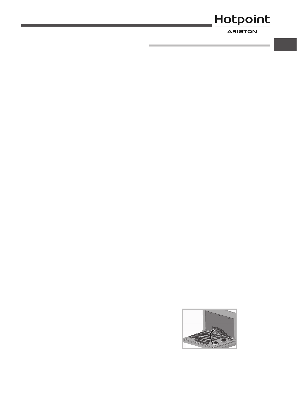
Remove any liquid from the lid before opening it. Do
not close the glass cover (if present) when the gas
burners or electric hotplates are still hot.
The appliance is not intended to be operated by
means of an external timer or separate remote
control system.
CAUTION: the use of inappropriate hob guards can
cause accidents.
UWAGA: Ryzyko pożaru: nie pozostawiać
przedmiotów na powierzchniach grzejnych.
Nie stosować nigdy oczyszczaczy parowych lub
ciśnieniowych do czyszczenia urządzenia.
Usunąć ewentualne płyny na pokrywie przed jej
otwarciem. Nie zamykać szklanej pokrywy (jeśli jest
częścią wyposażenia), jeśli palniki gazowe lub płyta
elektryczna są jeszcze rozgrzane.
Urządzenie nie jest przeznaczone do włączania przy
użyciu zewnętrznego przekaźnika czasowego lub
zdalnego systemu sterowania.
UWAGA: użycie niewłaściwych zabezpieczeń płyty
może być przyczyną wypadków.
3
Page 4

Hoiatused
Įspėjimai
HOIATUS: sisselülitatud seade ja selle
juurdepääsetavad osad muutuvad kasutamise
ajal kuumaks. Olge ettevaatlik ja vältige kontakti
kütteelementidega. Alla 8-aastased lapsed tuleb
hoida seadmest eemal, v.a. juhul, kui neile on
tagatud pidev järelevalve. Vanemad kui 8-aastased
lapsed ja isikud, kellel on vähenenud füüsilised
või vaimsed võimed või vähesed kogemused ja
oskused, võivad seda seadet kasutada juhul, kui on
tagatud nende järelevalve ning neile on antud juhised
seadme ohutuks kasutamiseks ja nad mõistavad
seadme kasutamisest tulenevaid ohte. Lapsed ei
tohi seadmega mängida. Lapsed võivad seadet
puhastada ja hooldada ainult järelevalve all.
HOIATUS: rasvas või õlis küpseva toidu jätmine
keeduplaadile järelevalveta on ohtlik ja võib
põhjustada tulekahju. Tulekahju kustutamiseks
ÄRGE kasutage vett, vaid lülitage seade välja ja
seejärel katke leek näiteks kaane või tuletekiga.
HOIATUS: Tuleoht: ärge hoidke keeduplaatidel
mingeid esemeid.
Ärge kasutage seadme puhastamiseks auru- ega
survepuhastusseadmeid.
Enne kaane avamist eemaldage sellele kogunenud
vedelik. Ärge sulgege klaaskaant (kui on olemas),
kui gaasipõletid või elektrilised keeduplaadid on veel
kuumad.
ĮSPĖJIMAS! Prietaisas ir jo pasiekiamos dalys
naudojant įkaista. Būkite atsargūs, neprisilieskite
prie įkaitusių prietaiso dalių. Jaunesni nei 8 metų
vaikai gali būti prileidžiami prie prietaiso tik jei
juos prižiūri suaugusieji. Vyresni nei 8 metų vaikai
ir asmenys, turintys zinių, jutimo ar psichinių
sutrikimų arba nepakankamai žinių ar patirties, šiuo
prietaisu gali naudotis tik tuomet, jei jie prižiūrimi
arba instruktuojami, kaip saugiai naudoti prietaisą,
ir supranta kylančias grėsmes. Vaikams turi būti
draudžiama žaisti su prietaisu. Neprižiūrimi vaikai taip
pat negali valyti prietaiso ar atlikti jo priežiūros darbų.
ĮSPĖJIMAS! Ant įjungtos viryklės palikti indai su
riebalais ar aliejumi gali sukelti gaisrą. NIEKADA
nebandykite liepsnos gesinti vandeniu – išjunkite
prietaisą ir kuo nors uždenkite liepsną, pavyzdžiui,
dangčiu arba priešgaisriniu apklotu.
ĮSPĖJIMAS! Gaisro pavojus – ant viryklės nelaikykite
jokių daiktų.
Niekuomet nevalykite prietaiso gariniais ar slėginiais
valikliais.
Prieš atidarydami gaubtą nuo jo nuvalykite skysčius.
Neuždenkite stiklinio dangčio (jei sumontuotas), kol
neatvėso dujiniai degikliai arba elektrinė kaitlentė.
Prietaisas nevaldomas išoriniu laikmačiu arba atskira
nuotoline valdymo sistema.
Seade ei ole mõeldud kasutamiseks koos välise
taimeri ega eraldiseisva kaugjuhtimissüsteemiga.
TÄHELEPANU: valede keeduplaadipiirete
kasutamine võib põhjustada õnnetusi.
4
ATSARGIAI! Netinkamų viryklės apsaugų naudojimas
gali sukelti nelaimingą atsitikimą.
Page 5
Brīdinājumi
Avertismente
BRĪDINĀJUMS! Ierīce un tās atklātās daļas
lietošanas laikā stipri sakarst. Nepieskarieties
sakarsušajām ierīces daļām. Bērni, kuri ir jaunāki par
astoņiem gadiem, drīkst atrasties ierīces tuvumā tikai
stingrā pieaugušo uzraudzībā. Ierīci drīkst lietot bērni,
kuri ir sasnieguši astoņu gadu vecumu, bet personas
ar ierobežotām ziskajām, maņu vai garīgajām
spējām un personas, kurām nav ierīces lietošanas
pieredzes vai nepieciešamo zināšanu, - tikai tad, ja
tās tiek uzraudzītas vai ir atbilstoši informētas par
ierīces drošu lietošanu un iespējamajiem riskiem.
Bērni nedrīkst rotaļāties ar ierīci. Bērni nedrīkst bez
uzraudzības tīrīt ierīci un veikt tās apkopi.
BRĪDINĀJUMS! Atstājot uz ieslēgtas plīts virsmas
pannu ar taukiem vai eļļu, varat radīt ugunsgrēka
risku. NEKĀDĀ GADĪJUMĀ nemēģiniet dzēst uguni
ar ūdeni, bet izslēdziet plīti un nosedziet liesmu ar
vāku vai nedegošu pārsegu.
ATENŢIE: Acest aparat şi părţile sale accesibile devin
foarte calde în timpul folosirii.Trebuie să ţi atenţi şi să
nu atingeţi elementele de încălzire.Îndepărtaţi copiii
sub 8 ani dacă nu sunt supravegheaţi continuu.Acest
aparat poate utilizat de copiii de peste 8 ani şi de
persoane cu capacităţi zice, senzoriale sau mentale
reduse sau fără experienţă şi cunoştinţe dacă se
află sub o supraveghere corespunzătoare sau
dacă au fost instruiţi cu privire la folosirea aparatului
în mod sigur şi dacă îşi dau seama de pericolele
corelate. Copiii nu trebuie să se joace cu aparatul.
Operaţiunile de curăţare şi de întreţinere nu trebuie
să e efectuate de copii fără supraveghere.
AVERTISMENT: Gătitul nesupravegheat pe o plită cu
grăsime sau ulei poate periculos şi poate lua foc.
Nu încercaţi NICIODATĂ să stingeţi focul cu apă, ci
opriţi aparatul şi apoi acoperiţi acăra, de exemplu,
cu un capac sau cu o pătură de incendiu.
BRĪDINĀJUMS! Aizdegšanās risks: neglabājiet
priekšmetus uz plīts virsmas.
Ierīci nedrīkst tīrīt ar tvaika vai augstspiediena
tīrītājiem.
Pirms pārsega atvēršanas notīriet no tā visu
šķidrumu. Ja gāzes degļi vai elektriskās sildvirsmas
joprojām ir karstas, stikla pārsegu (ja tāds ir) nedrīkst
aizvērt.
Iekārtu nav paredzēts lietot kopā ar ārējo taimeri vai
atsevišķu tālvadības ierīci.
UZMANĪBU! Neatbilstošu plīts virsmas aizsargu
lietošana var izraisīt nelaimes gadījumus.
AVERTISMENT: Pericol de incendiu: nu păstraţi
articole pe suprafeţele de gătit.
Nu folosiţi niciodată produse de curăţare cu aburi
sau sub presiune pe aparat.
Îndepărtaţi orice lichid de pe capac înainte de a-l
deschide. Nu închideţi capacul de sticlă (dacă există)
când arzătoarele pe gaz sau plitele electrice sunt
încă erbinţi.
Aparatul nu este conceput să funcţioneze prin
intermediul unui temporizator extern sau a unui
sistem separat de control la distanţă.
ATENŢIE: Utilizarea unor protecţii nepotrivite ale plitei
poate provoca accidente.
5
Page 6

Запобіжні заходи
УВАГА! Під час роботи цей прилад, а також
його доступні частини нагріваються до високих
температур.Слід бути особливо обережними, щоб
не торкатися нагрівальних елементів.Діти віком до
8 років мають знаходитися на небезпечній відстані
від приладу, якщо неможливо забезпечити
постійний контроль над ними.Дозволяється
користування цим приладом дітьми віком від 8
років, а також особами з обмеженими фізичними,
сенсорними або розумовими можливостями або
особами без належного досвіду і знань, якщо
вони перебувають під постійним контролем або
проінструктовані щодо правил з небезпечного
користування приладу і усвідомлюють ступені
ризику. Не дозволяйте дітям гратися з приладом.
Операції з очищення і догляду не повинні
виконуватися дітьми без належного контролю.
УВАГА: використання невідповідних захисних
пристроїв варильної поверхні може призвести до
нещасних випадків.
УВАГА: Небезпечно залишати без нагляду плити
з жиром або олією, тому що це може призвести
до пожежі.
НІ В ЯКОМУ РАЗІ не слід намагатися погасити
полум’я/пожежу водою. Необхідно вимкнути
прилад і накрити полум’я, наприклад, кришкою
або вогнетривким покривалом.
УВАГА: Небезпека пожежі: не залишайте речі на
варильних поверхнях.
Забороняється використання апаратів для
очищення парою або високим тиском.
Витріть насухо всі наявні на кришці рідини, перш
ніж відкрити її. Не закривайте скляну кришку
(якщо вона наявна), якщо газові пальники або
електричні конфорки залишаються нагрітими.
Не передбачено увімкнення приладу за допомогою
зовнішнього таймеру або окремої системи
дистанційного керування.
6
Page 7
Assistance
Communicating:
• the type of problem encountered.
• appliance model (Mod.)
• serial number (S/N)
This information is found on the data plate located on the appliance and/or
on the packaging.
Asistenţă
Comunicaţi:
• tipul de anomalie
• modelul aparatului (Mod.)
• numărul de serie (S/N)
Această informaţie se aă pe plăcuţa cu date amplasată pe aparat şi/sau
pe ambalaj.
Serwis Techniczny
Należy podać:
• rodzaj anomalii
• model urządzenia (Mod.)
• numer seryjny (S/N)
Te dane znajdują się na tabliczce znamionowej w lodówce, po lewej stronie
w dolnj jej części.
Klienditugi
Hoidke käepärast järgmised andmed:
• tüüpi anomaalia
• seadme mudel (Mod.)
• seerianumber (S/N)
Need andmed leiate seadme andmeplaadilt ja/või pakendilt.
Pagalba
Informacija:
• tipas anomalija
• prietaiso modelis (Mod.)
• Serijos numeris (S/N)
Šią informaciją rasite duomenų plokštelėje, kuri yra ant prietaiso ir (arba)
pakuotės.
Допомога
Повідомити:
• тип несправності;
• модель приладу (Mod.)
• cерійний номер (S/N)
Ці дані знаходяться на табличці з даними на самому приладі.
Palīdzība
Paziņojums:
• tipa anomālija
• ierīces modelis (Mod.)
• sērijas numurs (S/N)
Šī informācija ir norādīta uz tehnisko datu plāksnītes, kas piestiprināta ierīcei
un/vai tās iepakojumam.
7
Page 8
Description of the appliance
1
2
5
Seadme kirjeldus
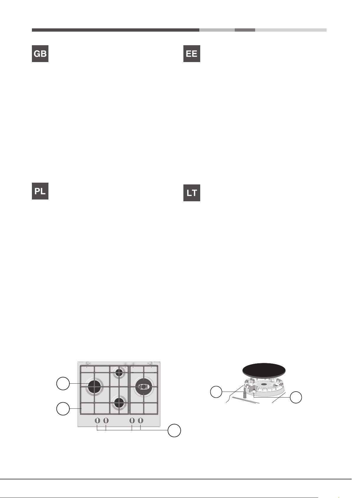
Overall view
1. Support Grid for COOKWARE
2. GAS BURNERS
3. Control Knobs for GAS BURNERS
4. Ignition for GAS BURNERS
5. SAFETY DEVICES
• GAS BURNERS differ in size and power. Use the diameter of the cookware
to choose the most appropriate burner to cook with.
• Control Knobs for GAS BURNERS adjust the size of the ame.
• GAS BURNER IGNITION enables a specic burner to be lit automatically.
• SAFETY DEVICE stops the gas flow if the flame is accidentally
extinguished.
Opis urządzenia
Widok ogólny
1. Kratki do ustawiania NACZYŃ DO GOTOWANIA
2. PALNIKI GAZOWE
3. Pokrętła sterujące PALNIKÓW GAZOWYCH
4. Świeca zapłonowa PALNIKÓW GAZOWYCH
5. URZĄDZENIA ZABEZPIECZAJĄCE
• PALNIKI GAZOWE posiadają różne wymiary i moce. Należy wybrać ten
palnik, który jest najbardziej odpowiedni dla średnicy używanego naczynia.
• Pokrętła sterowania palnikami gazowymi do regulowania płomienia.
• Świeca zapłonowa PALNIKÓW GAZOWYCH umożliwia automatyczne
zapalenie wybranego palnika.
• URZĄDZENIE ZABEZPIECZAJĄCE w razie przypadkowego zgaśnięcia
płomienia przerywa dopływ gazu.
Ülevaade
1. Rest KEEDUNÕU JAOKS
2. GAASIPÕLETID
3. GAASIPÕLETITE REGULEERIMISE NUPUD
4. GAASIPÕLETITE SÜÜTENUPP
5. OHUTUSSEADISED
• GAASIPÕLETID on erineva suuruse ja võimsusega. Kasutage põleti jaoks
kõige sobivama läbimõõduga keedunõud.
• GAASIPÕLETITE REGULEERIMISE NUPUD leegi reguleerimiseks.
• GAASIPÕLETI SÜÜTENUPP võimaldab vastava põleti automaatselt
süüdata.
• OHUTUSSEADIS seiskab gaasivoolu, kui leek peaks juhuslikult kustuma.
Prietaiso aprašymas
Bendras vaizdas
1. GAMINIMO INDO laikančiosios grotelės
2. DUJŲ DEGIKLIAI
3. DUJINIŲ DEGIKLIŲ valdymo rankenėlės
4. DUJINIŲ DEGIKLIŲ uždegimo funkcija
5. SAUGOS ĮTAISAI
• DUJINIAI DEGIKLIAI skiriasi dydžiu ir galia. Naudokite tokio skersmens
gaminimo indus, kurie geriausiai tinka tam tikram degikliui.
• DUJINIŲ DEGIKLIŲ valdymo rankenėlės liepsnai reguliuoti.
• DUJINIO DEGIKLIO UŽDEGIMO FUNKCIJA suteikia galimybę
automatiškai uždegti tam tikrą degiklį.
• APSAUGINIS ĮTAISAS sustabdo dujų srautą, jei liepsna netyčia užgęsta.
4
3
8
Page 9
Ierīces apraksts
1
2
5
Опис приладу
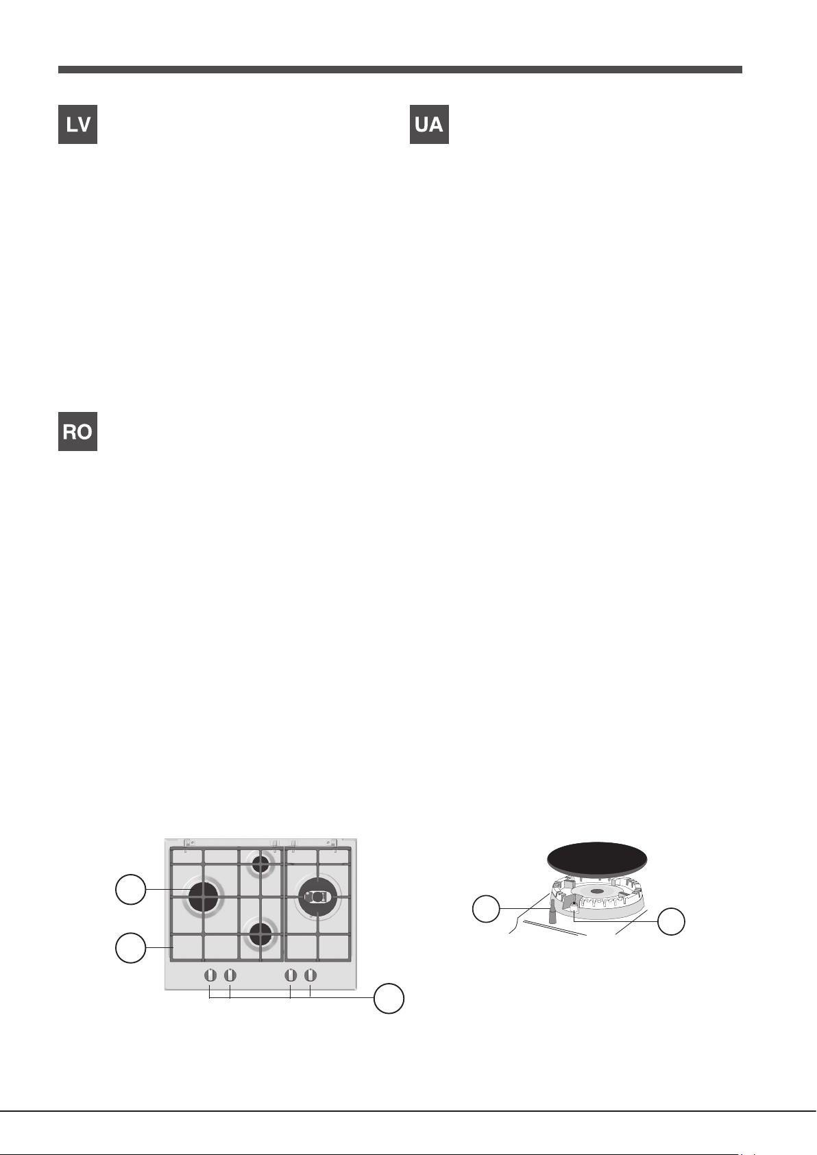
Vispārīga informācija
1. GATAVOŠANAS TRAUKU balsta režģis
2. GĀZES DEGĻI
3. GĀZES DEGĻU vadības slēdži
4. Aizdedzes GĀZES DEGĻIEM
5. DROŠĪBAS IERĪCES
• GĀZES DEGĻIEM ir dažādi izmēri un jauda. Gatavojot izvēlieties
gatavošanas trauka diametram atbilstošāko degli.
• GĀZES DEGĻU vadības slēdži liesmas regulēšanai.
• GĀZES DEGĻA AIZDEDZE ļauj automātiski aizdedzināt īpašu degli.
• DROŠĪBAS IERĪCE aptur gāzes plūsmu, ja liesma tiek nejauši nodzēsta.
Descrierea aparatului
Vedere de ansamblu
1. Grătar suport pentru VASE
2. ARZĂTOARELE DE GAZE
3. Butoane de control pentru ARZĂTOARE DE GAZE
4. Aprindere pentru ARZĂTOARE DE GAZE
5. DISPOZITIVE DE SIGURANŢĂ
Загальний вигляд
1. Підтримуюча Решітка для ПОСУДУ
2. ГАЗОВІ ПАЛЬНИКИ
3. Ручки управління ГАЗОВИХ ПАЛЬНИКІВ
4. Запалювання для ГАЗОВИХ ПАЛЬНИКІВ
5. ПРИСТРОЇ БЕЗПЕКИ
• ГАЗОВІ ПАЛЬНИКИ відрізняються за розмірами тапотужністю.
Використовуйте для приготування їжі посудз діаметром у відповідності
до розміру найбільшпідходящого пальника.
• ГАЗОВИMИПАЛЬНИКAMИ
полум’я
• Запалювання для ГАЗОВИХ ПАЛЬНИКІВ дозволяють, привключенні,
запалювати конкретні пальники автоматично.
• ПРИСТРІЙ БЕЗПЕКИ зупиняє потік газу, якщо полум’явипадково
гасне.
• ARZĂTOARELE DE GAZE diferă ca mărime şi putere. Utilizaţi diametrul
vaselor pentru a alege cel mai potrivit arzător pentru gătit.
• Butoane de control pentru ARZĂTOARE DE GAZE pentru reglarea ăcării.
• APRINDEREA ARZĂTORULUI CU GAZ permite unui anumit arzător să
se aprindă în mod automat.
• DISPOZITIVUL DE SIGURANŢĂ opreşte uxul de gaz dacă acăra se
stinge accidental.
3
4
9
Page 10
Installation
555 mm
55 mm
475 mm
GB
! Before operating your new appliance please read this instruction booklet
carefully. It contains important information for safe use, installation and care
of the appliance.
! Please keep these operating instructions for future reference. Pass them on
to possible new owners of the appliance.
Positioning
! Keep packaging material out of the reach of children. It can become a choking
or suffocation hazard (see Precautions and tips).
! The appliance must be installed by a qualied professional according to the
instructions provided. Incorrect installation may cause harm to people and
animals or may damage property.
! This unit may be installed and used only in permanently ventilated rooms
in accordance with current national regulations. The following requirements
must be observed:
• The room must be equipped with an air extraction system that expels
any combustion fumes. This may consist of a hood or an electric fan that
automatically starts each time the appliance is switched on.
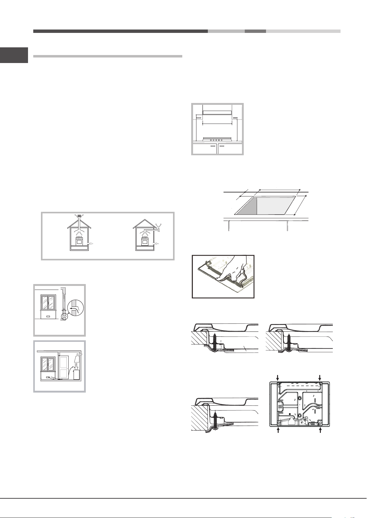
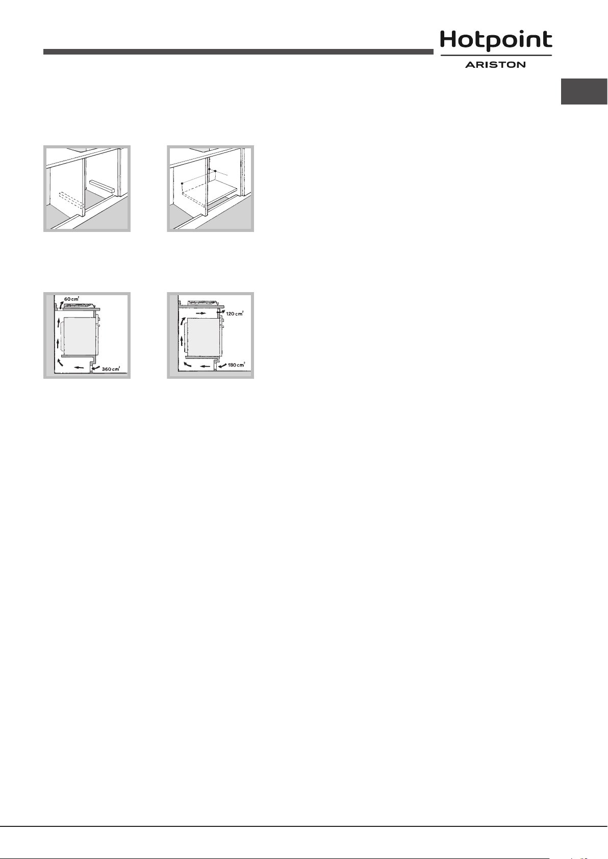
Fitting the appliance
The following precautions must be taken when installing the hob:
• Kitchen cabinets adjacent to the appliance and taller than the top of the
hob must be at least 200 mm from the edge of the hob.
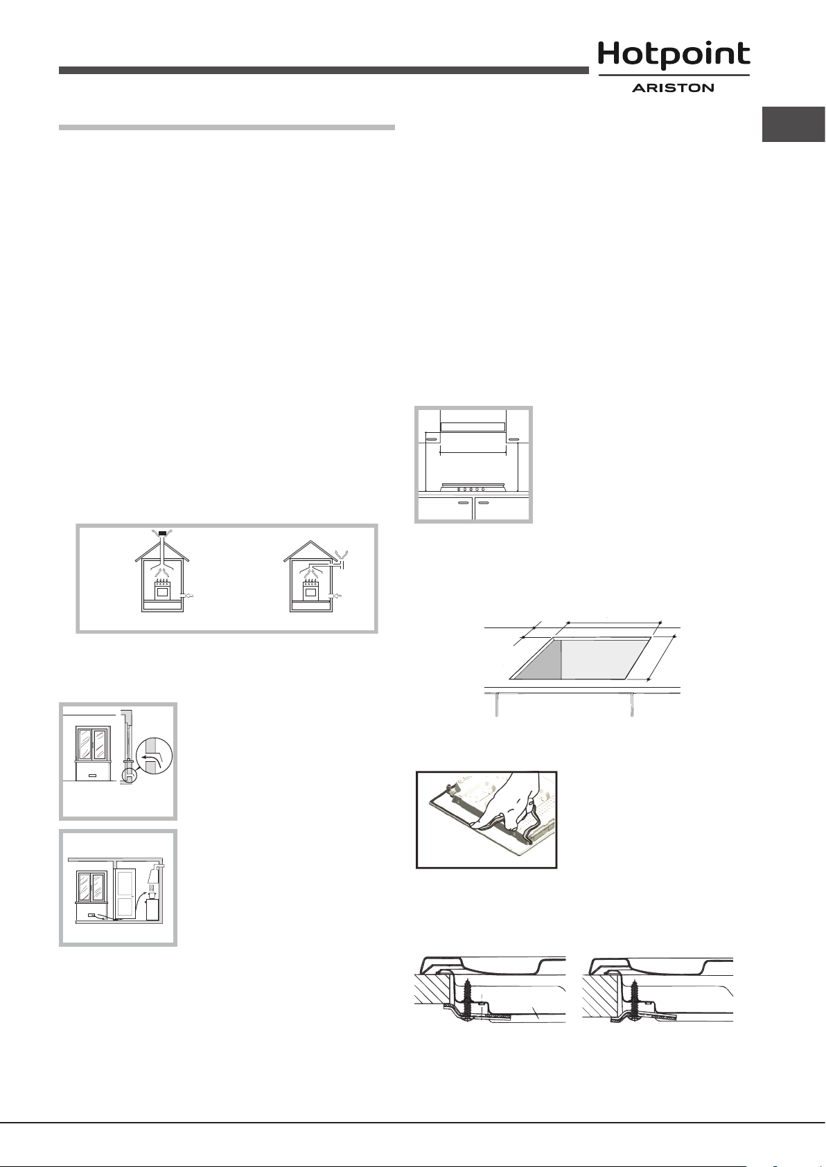
• Hoods must be installed according to their relative installation instruction
manuals and at a minimum distance of 650 mm from the hob (see gure).
• Place the wall cabinets adjacent to the hood at a minimum height of 420
mm from the hob (see gure).
If the hob is installed beneath a wall cabinet,
the latter must be situated at a minimum of 700
600mm min.
650mm min.
mm above the hob.
420mm min.
• The installation cavity should have the dimensions indicated in the gure.
Fastening hooks are provided, allowing you to fasten the hob to tops that
are between 20 and 40 mm thick. To ensure the hob is securely fastened
to the top, we recommend you use all the hooks provided.
In a chimney stack or branched flue.
(exclusively for cooking appliances)
Directly to
the Outside
• The room must also allow proper air circulation, as air is needed for
combustion to occur normally. The ow of air must not be less than 2 m3/h
per kW of installed power.
The air circulation system may take air directly
from the outside by means of a pipe with an
inner cross section of at least 100 cm
2
; the
opening must not be vulnerable to any type
Examples of
ventilation holes
for comburant air.
Adjacent
Room
A
Room to be
Vented
of blockages.
The system can also provide the air needed for
combustion indirectly, i.e. from adjacent rooms
tted with air circulation tubes as described
above. However, these rooms must not be
communal rooms, bedrooms or rooms that
may present a re hazard.
Enlarging the ventilation slot
between window and floor.
• Intensive and prolonged use of the appliance may necessitate
supplemental ventilation, e.g. opening a window or increasing the power
of the air intake system (if present).
• Liquid petroleum gas sinks to the oor as it is heavier than air. Therefore,
rooms containing LPG cylinders must also be equipped with vents to allow
gas to escape in the event of a leak. As a result LPG cylinders, whether
partially or completely full, must not be installed or stored in rooms or
storage areas that are below ground level (cellars, etc.). It is advisable to
keep only the cylinder being used in the room, positioned so that it is not
subject to heat produced by external sources (ovens, replaces, stoves,
etc. ) which could raise the temperature of the cylinder above 50°C.
10
Before the installation remove the grids and burners from the hob and turn it
upside down, making sure you don’t damage the thermocouples and spark
plugs.
Apply the seals that come with the
appliance along the outer edges of
the hob to prevent any passage of air,
humidity and water (see Figure).
For proper application make sure the
surfaces to be sealed are clean, dry and
free of any grease/oil.
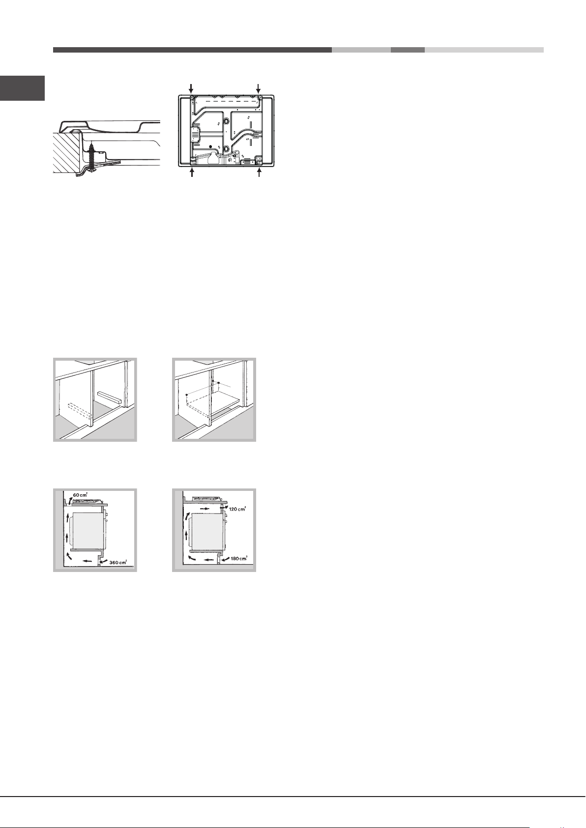
Hook fastening diagram
Hooking position for top H=20mm Hooking position for top H=30mm
Front
Hooking position for top H=40mm Back
! Use the hooks contained in the “accessory pack”.
• Where the hob is not installed over a built-in oven, a wooden panel must
be installed as insulation. This must be placed at a minimum distance of
20 mm from the lower part of the hob.
Page 11
Ventilation
To ensure adequate ventilation, the back panel of the cabinet must be
removed. It is advisable to install the oven so that it rests on two strips of
wood, or on a completely at surface with an opening of at least 45 x 560
mm (see diagrams).
45 mm.
560 mm.
! The cable must be checked regularly and replaced by authorised technicians
only (see Assistance).
! The manufacturer declines any liability should these safety measures not
be observed.
Gas connection
The appliance should be connected to the main gas supply or to a gas
cylinder in compliance with current national regulations. Before carrying out
the connection, make sure the cooker is compatible with the gas supply you
wish to use. If this is not the case, follow the instructions indicated in the
paragraph “Adapting to different types of gas.”
When using liquid gas from a cylinder, install a pressure regulator which
complies with current national regulations.
GB
Where a hob is installed above an oven without a forced ventilation cooling
system, adequate ventilation must be provided inside the cabinet by means
of air holes through which air can pass (see gure).
! Check that the pressure of the gas supply is consistent with the values
indicated in Table 1 (“Burner and nozzle specications”). This will ensure the
safe operation and longevity of your appliance while maintaining efcient
energy consumption.
Connection with a rigid pipe (copper or steel)
! Connection to the gas system must be carried out in such a way as not to
place any strain of any kind on the appliance.
There is an adjustable L-shaped pipe tting on the appliance supply ramp
and this is tted with a seal in order to prevent leaks. The seal must always
be replaced after rotating the pipe tting (seal provided with appliance). The
gas supply pipe tting is a threaded 1/2 gas cylindrical male attachment.
Electrical connection
Hobs equipped with a three-pole power supply cable are designed to operate
with alternating current at the voltage and frequency indicated on the data
plate (this is located on the lower part of the appliance). The earth wire in the
cable has a green and yellow cover. If the appliance is to be installed above
a built-in electric oven, the electrical connection of the hob and the oven must
be carried out separately, both for electrical safety purposes and to make
extracting the oven easier.
Connecting the supply cable to the mains
Install a standardised plug corresponding to the load indicated on the data
plate.
The appliance must be directly connected to the mains using an omnipolar
circuit-breaker with a minimum contact opening of 3 mm installed between the
appliance and the mains. The circuit-breaker must be suitable for the charge
indicated and must comply with current electrical regulations (the earthing
wire must not be interrupted by the circuit-breaker). The supply cable must
not come into contact with surfaces with temperatures higher than 50°C.
! The installer must ensure that the correct electrical connection has been
made and that it is compliant with safety regulations.
Before connecting to the power supply, make sure that:
• the appliance is earthed and the plug is compliant with the law.
• the socket can withstand the maximum power of the appliance, which is
indicated on the data plate.
• the voltage is in the range between the values indicated on the data plate.
• the socket is compatible with the plug of the appliance. If the socket is
incompatible with the plug, ask an authorised technician to replace it. Do
not use extension cords or multiple sockets.
! Once the appliance has been installed, the power supply cable and the
electrical socket must be easily accessible.
! The cable must not be bent or compressed.
Connecting a flexible jointless stainless steel pipe to a threaded
attachment
The gas supply pipe tting is a threaded 1/2 gas cylindrical male attachment.
These pipes must be installed so that they are never longer than 2000 mm
when fully extended. Once connection has been carried out, make sure that
the exible metal pipe does not touch any moving parts and is not compressed.
! Only use pipes and seals that comply with current national regulations.
Checking the tightness of the connection
! When the installation process is complete, check the pipe ttings for leaks
using a soapy solution. Never use a ame.
Adapting to different types of gas
To adapt the hob to a different type of gas other than default type (indicated
on the rating plate at the base of the hob or on the packaging), the burner
nozzles should be replaced as follows:
1. Remove the hob grids and slide the burners off their seats.
2. Unscrew the nozzles using a 7 mm socket spanner, and replace them
with nozzles for the new type of gas (see table 1 “Burner and nozzle
characteristics”).
3. Reassemble the parts following the above procedure in the reverse order.
4. Once this procedure is nished, replace the old rating sticker with one
indicating the new type of gas used. Sticker are available from any of our
Service Centres.
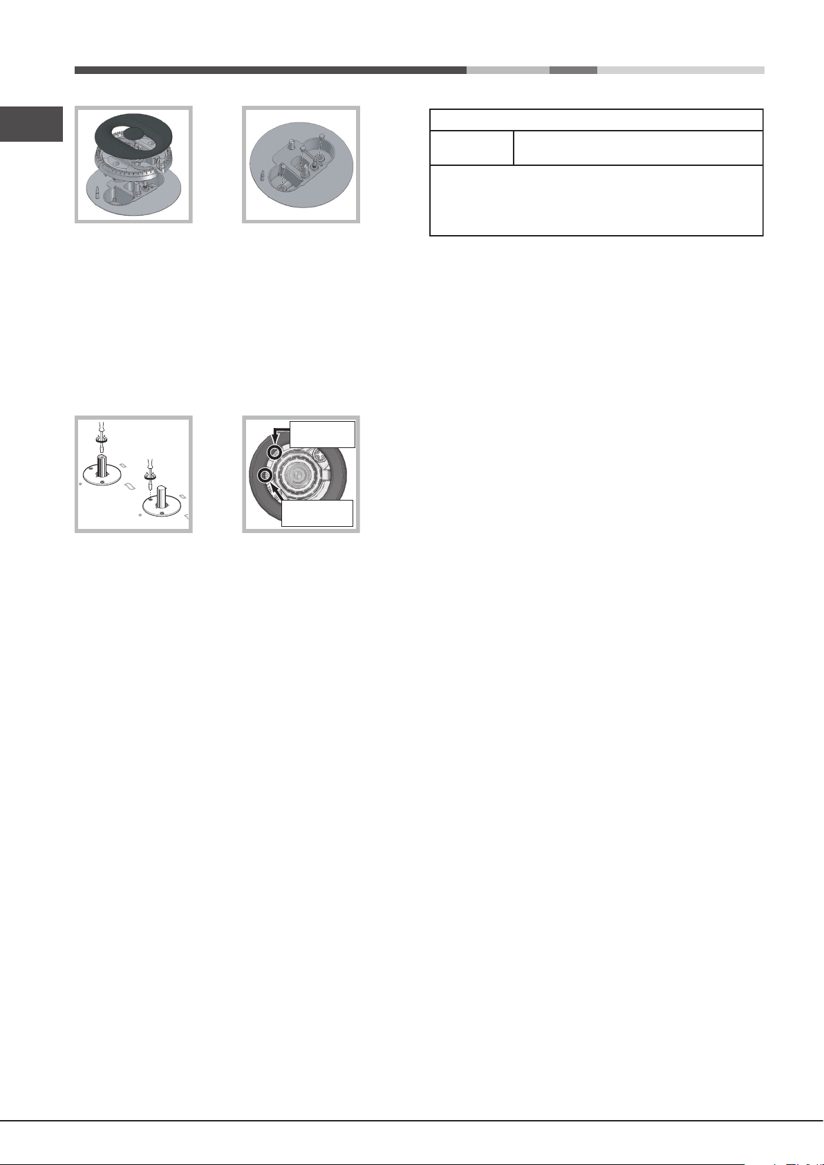
Replacing the nozzles on separate “double ame “ burners
1. Remove the grids and slide the burners from their housings. The burner
consists of 2 separate parts (see gure);
2. Unscrew the burers with a 7 mm wrench spanner. The internal burner
has a nozzle, the external burner has two (of the same size). Replace
the nozzle with models suited to the new type of gas (see table 1).
3. Replace all the components by repeating the steps in reverse order.
11
Page 12
GB
• Adjusting the burners’ primary air
Does not require adjusting.
• Setting the burners to minimum
1. Turn the tap to the low ame position;
2. Remove the knob and adjust the adjustment screw, which is positioned
in or next to the tap pin, until the ame is small but steady.
! In the event of single-control DRDA (DCDR) burners, adjustment can be
performed by intervening on the 2 screws located near the tap pin (see picture).
Total DRDA
(DCDR) burner
adjustment
Inner DRDA (DCDR)
burner adjustment
DATA PLATE
Electrical
connections
see data plate
ECODESIGN
This appliance conforms to the EU Regulation no. 66/2014
implementing Directive 2009/125/EC.
standard EN 30-2-1
3. Having adjusted the ame to the required low setting, while the burner is
alight, quickly change the position of the knob from minimum to maximum
and vice versa several times, checking that the ame does not go out.
4. Some appliances have a safety device (thermocouple) tted. If the device
fails to work when the burners are set to the low ame setting, increase
this low ame setting using the adjusting screw.
5. Once the adjustment has been made, replace the seals on the by-passes
using sealing wax or a similar substance.
6. In the event of discrete-adjustment knobs with LED visualisation, turn the
knob to the minimum power setting them remove it and intervene on the
adjustment screw located near the tap pin.
7. Minimum setting adjustment of the DRDA (DCDR) burner with discrete
adjustment and LED visualisation:
• To adjust the outer ring, turn the knob anti-clockwise to the minimum
power position.
• To adjust the minimum power setting of the inner ring, turn the knob
clockwise to the minimum power position.
• Remove the knob and intervene on the adjustment screw located near
the tap pin.
! If the appliance is connected to liquid gas, the regulation screw must be
fastened as tightly as possible.
! Once this procedure is nished, replace the old rating sticker with one
indicating the new type of gas used. Stickers are available from any of our
Service Centres.
! Should the gas pressure used be different (or vary slightly) from the
recommended pressure, a suitable pressure regulator must be tted to the
inlet pipe (in order to comply with current national regulations).
12
Page 13
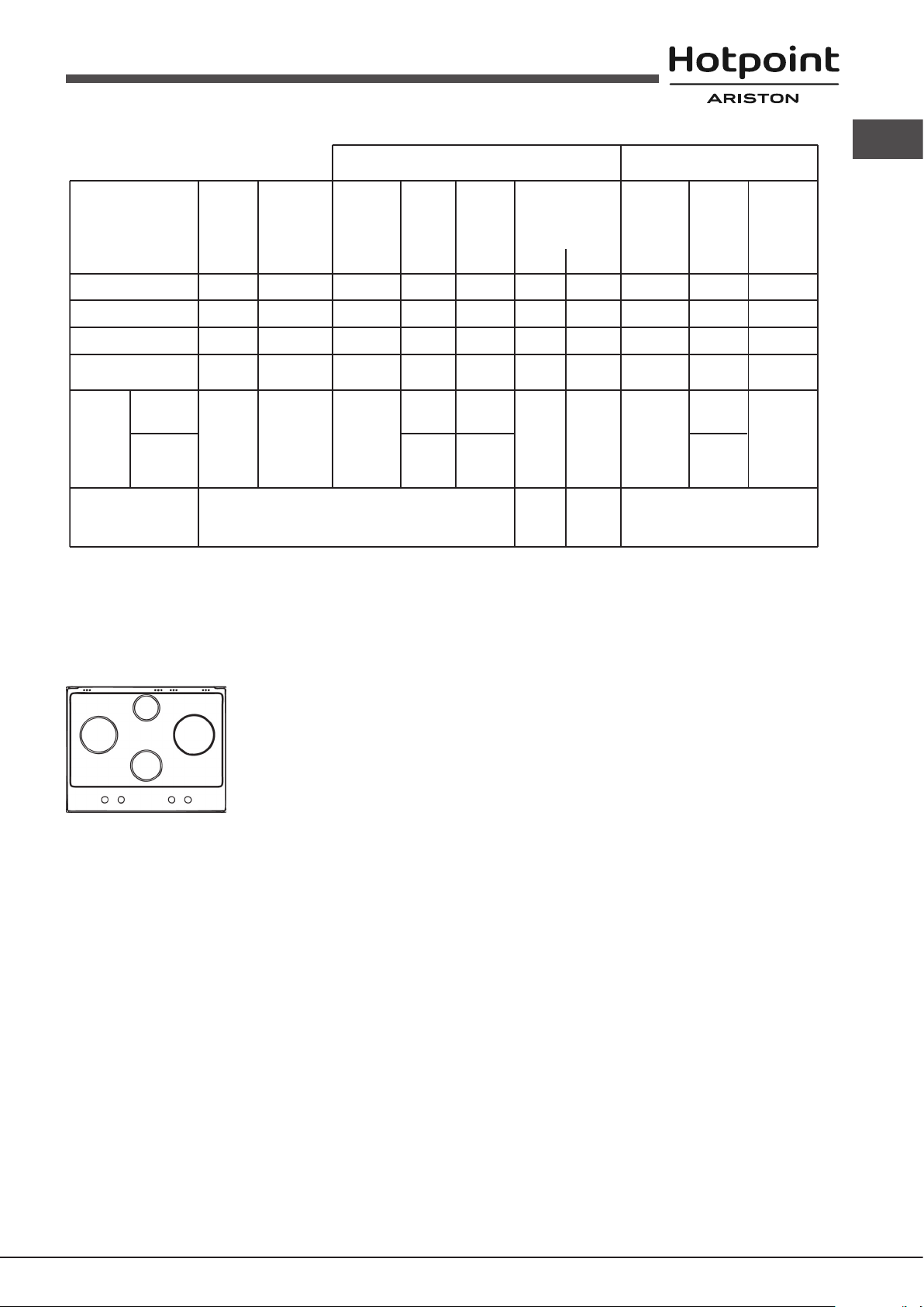
Table 1 Liquid Gas Natural Gas
Burner and nozzle specifications
Natural P.C.S. = 37.78 MJ/m³
Burner Diameter Thermal Thermal By-pass Nozzle Flow* Thermal Nozzle Flow*
power power 1/100 1/100 (g/h) power 1/100 (l/h)
kW kW kW
(p.c.s.*) (p.c.s.*) (p.c.s.*)
(mm) Reduced Nominal (mm) (mm) *** ** Nominal (mm)
Reduced Rapid (RR)
100
0.80
2.70
39
80
196
193
2.70
122(H3)
257
GB
Semi Rapid (S)
Auxiliary (A)
Double flame
(DCDR internal) (1)
Double
flame (1)
Supply pressures Nominal (mbar)
(1) For single-control DRDA (DCDR) burner only
* At 15°C and 1013,25 mbar - dry gas
** Propane P.C.S. = 50.37 MJ/Kg
*** Butane P. C.S. = 49.47 MJ/Kg
(DCDR
internal)
(DCDR
external
2 nozzle)
75
55
36
130
0.45
0.45
0.40
1.65
1.75
1.05
0.90
3.60
Minimum (mbar)
Maximum (mbar)
A
RR
DC
28
28
29
29
57
64
50
44
44
60x2
127
76
65
262
28-30
20
35
125
75
64
257
37
25
45
1.75
1.05
0.90
3.60
96(Z)
79(6)
74
74
94x2
20
17
25
167
100
86
343
S
PKLL 641 D2/IX/HA EE
13
Page 14
Start-up and use
GB
! The position of the corresponding gas burner is shown on every knob.
To turn on the inner ring only, position the knob on the symbol (max ) -
(min) then press and turn the knob clockwise. To switch modes, it is necessary
to switch off the burner.
Gas cooker hobs are equipped with discrete power adjustment that allows
for accurately adjusting the ame to 5 different power levels. Thanks to this
system, gas hobs are also capable of guaranteeing the same cooking results
for each recipe, as the optimal power level for the desired type of cooking can
be identied in an easier, more accurate way.
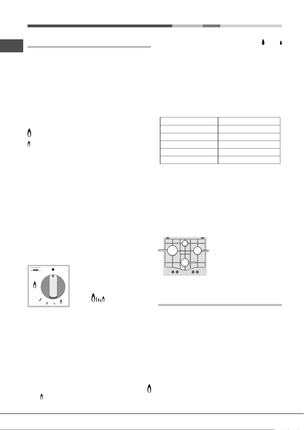
Gas burners
Each burner can be adjusted to one of the following settings using the
corresponding control knob:
● Off
Maximum
Minimum
To light one of the burners, hold a lit match or lighter near the burner and, at
the same time, press down and turn the corresponding knob anti-clockwise
to the maximum setting.
Since the burner is tted with a safety device, the knob should be pressed
for approximately 2-3 seconds to allow the automatic device keeping the
ame alight to heat up.
When using models with an ignition button, light the desired burner pressing
down the corresponding knob as far as possible and turning it anticlockwise
towards the maximum setting.
! If a ame is accidentally extinguished, turn off the control knob and wait for
at least 1 minute before trying to relight it.
To switch off the burner, turn the knob in a clockwise direction until it stops
(when reaches the “●” position).
Discrete ame adjustment
The selected burner can be adjusted - by means of the knob - to 5 different
power levels.
To shift between levels, simply turn the knob
towards the desired power level.
A click signals the passage from one power
level to the other.The selected power level
is indicated by the corresponding symbol
To switch off the burner, press and turn the knob clockwise until it stops (when
it reaches the “●” position).
Practical advice on using the burners
To ensure the burners operate efciently:
• Use appropriate cookware for each burner (see table) so that the ames
do not extend beyond the bottom of the cookware.
• Always use cookware with a at base and a cover.
• When the contents of the pan reach boiling point, turn the knob to minimum.
Burner Ø Cookware diameter (cm)
Reduced Rapid (RR)
Semi Rapid (S)
Auxiliary (A)
Double Flame (DCDR internal)
Double Flame (DCDR external)
! On the models supplied with a reducer shelf, remember that this should be
used only for the Double ame internal (DCDR internal) burner when you use
casserole dishes with a diameter under 12 cm.
To identify the type of burner, refer to the designs in the section entitled, “Burner
and Nozzle Specications”.
• For maximum stability, always make sure that the pan supports are
correctly tted and that each pan is placed centrally over the burner.
• Pan handles should be positioned in line with one of the support bars on
the pan support grid.
• Pan handle should be positioned so not to protrude beyond the front edge
of the hob.
The more variable aspect in terms of pan
stability can often be the pan itself, (or
the positioning of that pan during use).
Well balanced pans, with at bases that
are placed centrally over the burner,
with the pan handles aligned with one
of the support ngers obviously offer the
greatest stability.
24 - 26
16 - 20
10 - 14
10 - 14
24 - 26
(symbols ) and, on hobs equipped with
a display, by the LEDs that turn on (5 = max.
power; 1 = min. power). The system guarantees accurate ame adjustment
and uniform cooking results by facilitating selection of the desired power level.
The “double-ame” burner*
This gas burner consists of two concentric ame rings that can operate jointly
or independently (in case of dual-control only).
As the burner is tted with a safety device, the knob should be pressed
down for approximately 2-3 seconds until the device keeping the ame
automatically alight heats up.
Single control:
The rings comprising the burner are activated through a single control knob.
To simultaneously turn on both rings, position the knob on the symbol
(max) - (min) then press and turn the knob anti-clockwise.
14
Precautions and tips
! This appliance has been designed and manufactured in compliance with
international safety standards. The following warnings are provided for safety
reasons and must be read carefully.
General safety
• This is a class 3 built-in appliance.
• Gas appliances require regular air exchange to maintain efcient
operation. When installing the hob, follow the instructions provided
in the paragraph on “Positioning” the appliance.
• These instructions are only valid for the countries whose symbols
appear in the manual and on the serial number plate.
• The appliance was designed for domestic use inside the home and is
not intended for commercial or industrial use.
• The appliance must not be installed outdoors, even in covered areas. It is
extremely dangerous to leave the appliance exposed to rain and storms.
Page 15
• Do not touch the appliance with bare feet or with wet or damp hands and
feet.
• The appliance must be used by adults only for the preparation of food,
in accordance with the instructions outlined in this booklet. Any other
use of the appliance (e.g. for heating the room) constitutes improper
use and is dangerous. The manufacturer may not be held liable for
any damage resulting from improper, incorrect and unreasonable
use of the appliance.
• Ensure that the power supply cables of other electrical appliances do not
come into contact with the hot parts of the oven.
• The openings used for ventilation and dispersion of heat must never be
covered.
• Always make sure the knobs are in the “●”/“○” position when the appliance
is not in use.
• When unplugging the appliance always pull the plug from the mains socket,
do not pull on the cable.
• Never carry out any cleaning or maintenance work without having detached
the plug from the mains.
• In case of malfunction, under no circumstances should you attempt to repair
the appliance yourself. Repairs carried out by inexperienced persons may
cause injury or further malfunctioning of the appliance. Contact a Service
Centre (see Assistance).
• Do not close the glass cover (if present) when the gas burners or electric
hotplates are still hot.
• The appliance should not be operated by people (including children)
with reduced physical, sensory or mental capacities, by inexperienced
individuals or by anyone who is not familiar with the product. These
individuals should, at the very least, be supervised by someone who
assumes responsibility for their safety or receive preliminary instructions
relating to the operation of the appliance.
• Do not let children play with the appliance.
• The appliance is not intended to be operated by means of an external
timer or separate remote-control system.
Disposal
• When disposing of packaging material: observe local legislation so that
the packaging may be reused.
• The European Directive 2012/19/EU on Waste Electrical and
Electronic Equipment (WEEE), requires that old household electrical
appliances must not be disposed of in the normal unsorted municipal
waste stream. Old appliances must be collected separately in order
to optimise the recovery and recycling of the materials they contain
and reduce the impact on human health and the environment.
The crossed out “wheeled bin” symbol on the product reminds you of your
obligation, that when you dispose of the appliance it must be separately
collected.
Consumers should contact their local authority or retailer for information
concerning the correct disposal of their old appliance.
Maintenance and care
GB
Switching the appliance off
Disconnect your appliance from the electricity supply before carrying out
any work on it.
Cleaning the hob surface
• All the enamelled and glass parts should be cleaned with warm water and
neutral solution.
• Stainless steel surfaces may be stained by calcareous water or aggressive
detergents if left in contact for too long. Any food spills (water, sauce, coffee,
etc.) should be wiped away before they dry.
• Clean with warm water and neutral detergent, and then dry with a soft
cloth or chamois. Remove baked-on dirt with specic cleaners for stainless
steel surfaces.
• Clean stainless steel only with soft cloth or sponge.
• Do not use abrasive or corrosive products, chlorine-based cleaners or pan
scourers.
• Do not use steam cleaning appliances.
• Do not use ammable products.
• Do not leave acid or alkaline substances, such as vinegar, mustard, salt,
sugar or lemon juice on the hob.
Cleaning the hob parts
• Clean the enamelled and glass parts only with soft cloth or sponge.
• Grids, burner caps and burners can be removed to be cleaned.
• Clean them by hand with warm water and non-abrasive detergent,
removing any food residues and checking that none of the burner openings
is clogged.
• Rinse and dry.
• Ret burners and burner caps correctly in the respective housings.
• When replacing the grids, make sure that the panstand area is aligned
with the burner.
• Models equipped with electrical ignition plugs and safety device require
thorough cleaning of the plug end in order to ensure correct operation.
Check these items frequently, and if necessary, clean them with a damp
cloth. Any baked-on food should be removed with a toothpick or needle.
! To avoid damaging the electric ignition device, do not use it when the
burners are not in their housing.
! It is not necessary to remove the pan supports in order to clean the hob
surface. Thanks to the support system, simply lift and hold the pan supports
or rotate them until they rest against a rear support.
Do not place the hot grids on top of the glass cover (if applicable),
otherwise the rubber plugs on the glass may be damaged.
Respecting and conserving the environment
• Cook your food in closed pots or pans with well-tting lids and use as little
water as possible. Cooking with the lid off will greatly increase energy
consumption.
• Use purely at pots and pans.
• If you are cooking something that takes a long time, it’s worth using a
pressure cooker, which is twice as fast and saves a third of the energy.
15
Page 16

Gas tap maintenance
GB
Over time, the taps may become jammed or difcult to turn. If this happens,
the tap must be replaced.
! This procedure must be performed by a qualied technician authorised
by the manufacturer.
Troubleshooting
It may happen that the appliance does not function properly or at all. Before
calling the service centre for assistance, check if anything can be done. First,
check to see that there are no interruptions in the gas and electrical supplies,
and, in particular, that the gas valves for the mains are open.
The burner does not light or the ame is not even around the burner.
Check whether:
• The gas holes on the burner are clogged.
• All the movable parts that make up the burner are mounted correctly.
• There are draughts near the appliance.
The ame dies in models with a safety device.
Check to make sure that:
• You pressed the knob all the way in.
• You keep the knob pressed in long enough to activate the safety device.
• The gas holes are not blocked in the area corresponding to the safety
device.
The burner does not remain lit when set to minimum.
Check to make sure that:
• The gas holes are not blocked.
• There are no draughts near the appliance.
• The minimum setting has been adjusted properly.
The cookware is unstable.
Check to make sure that:
• The bottom of the cookware is perfectly at.
• The cookware is positioned correctly at the centre of the burner.
• The pan support grids have been positioned correctly.
16
Page 17
Instalacja
555 mm
55 mm
475 mm
! Ważnym jest, aby zachować niniejszą instrukcję dla przyszłych konsultacji.
W razie sprzedaży, odsprzedania, czy przeniesienia, należy upewnić się,
czy znajduje się ona wraz z urządzeniem i odpowiednimi uwagami, aby
poinformować nowego właściciela o jego funkcjonowaniu.
GPL, niezaleznże od tego czy są puste, czy częściowo napełnione,
nie powinny być instalowane ani składowane w pomieszczeniach lub
komorach o położonych poniżej poziomu podłogi (piwnice, itp.). Dobrze
jest przechowywać w pomieszczeniu jedynie butle aktualnie użytkowaną,
umocowaną w sposób nie narażający jej na bezpośrednie oddziaływanie
źródeł ciepła (piece, kominki, piecyki, itp.) mogące doprowadzić do wzrostu
temperatury powietrza powyżej 50°C.
PL
! Należy uważnie przeczytać instrukcję: zawieraja ona ważne informacje
dotyczące instalacji, użytkowania i bezpieczeństwa.
Ustawienie
! Opakowania nie są zabawkami dla dzieci i należy je usunąć zgodnie z
normami zbierania odpadów (patrz Środki ostrożności i zalecenia).
! Instalacja powinna zostać wykonana zgodnie z niniejszymi instrukcjami i
przez personel zawodowo do tego przygotowany. Błędna instalacja może
spowodować powstanie szkód wobec osób, zwierząt lub rzeczy.
! Niniejsze urządzenie może zostać zainstalowane wyłącznie w
pomieszczeniach ze stałą wentylacją, zgodnie z zaleceniami obowiązujących
norm krajowych. Należy dochować następujących warunków:
• Pomieszczenie powinno posiadać system odprowadzający na zewnątrz
gazów spalinowych składający się z okapu lub wyciągu elektrycznego,
uruchamianego automatycznie każdorazowo podczas uruchomienia
urządzenia.
W kominie lub w odgałęzionym przewodzie dymnym
(przeznaczonym dla urządzeń kuchennych)
• Pomieszczenie powinno posiadać funkcjonalny system dopływu
powietrza umożliwiający normalne spalanie. Dopływ niezbędnego do
spalania powietrza nie powinien być mniejszy niż 2 m3/h na każdy kW
zainstalowanej mocy.
System może polegać na bezpośrednim
poborze powietrza z zewnątrz budynku przy
pomocy kanału o przekroju użytecznym
przynajmniej 100 cm2 i zabezpieczonego przed
A
Przykłady otwarcia
wentylacji
dla powietrza do spalania
Pomieszczenie
przyległe
Pomieszczenie
przeznaczone
do przewietrzania
przypadkowym zaślepieniem.
Albo też, w sposób pośredni, z przyległych
pomieszczeń wyposażonych w przewód
wentylacyjny jak opisany powyżej, a nie będący
częścią wspólną dla całej nieruchomości
ani nie mający połączeń z pomieszczeniami
sypialni lub w których występuje zagrożenie
Zwiększenie szczeliny pomiędzy
drzwiami a podłogą
pożarem.
Bezpośrednio
na zewnątrz
Zabudowa
W celu poprawnego zainstalowania płyty grzewczej należy zachować
następujące środki ostrożności:
• Meble znajdujące się obok, a których wysokość przekracza wysokość
płyty roboczej, powinny zostać odsunięte przynajmniej na 200 mm od
krawędzi płyty roboczej.
• Okapy powinny być zainstalowane zgodnie z warunkami wymaganymi
podanymi przez instrukcje samych okapów, jednak w minimalnej odległości
650 mm (patrz ilustracja).
• Umieścić sąsiadujące z okapem szafki wiszące na wysokości minimalne
od szczytu 420 mm (patrz ilustracja).
By płyta grzewcza mogła być zainstalowana
pod szafką wiszącą, ta ostatnia powinna
600mm min.
znajdować się w odległości minimalnej od
szczytu wynoszącej 700 mm.
650mm min.
420mm min.
• Wnęka na obudowę powinna mieć wymiary podane na ilustracji.
Przewidziano uchwyty mocujące umożliwiające zamocowanie płyty na
podstawie posiadającej grubość od 20 do 40 mm. Aby solidnie zamocować
płytę zaleca się zastosowanie wszystkich uchwytów znajdujących się do
dyspozycji.
Przed zainstalowaniem płyty kuchennej, należy zdjąć ruszty i palniki i odwrócić
ją częścią spodnią do góry, uważając na to, aby nie uszkodzić termopar i
świec zapłonowych.
Następnie należy założyć uszczelki
dostarczone na wyposażeniu na
zewnętrzne krawędzie płyty kuchennej,
aby uniemożliwić przedostawanie się
powietrza, wilgoci i wody (zob. rysunek).
Aby wykonać powyższą czynność
prawidłowo, należy upewnić się, że
uszczelniane powierzchnie są czyste, suche i nie są zabrudzone smarami/
olejami.
Schemat mocowania uchwytów
• Intensywne i długotrwałe stosowanie urządzenia może wymagać
dodatkowej wentylacji, na przykład otwarcia okna lub bardziej skutecznej
wentylacji, zwiększającej mechaniczną siłę ssania (jeśli już istnieje).
• Skroplone gazy pochodne ropy naftowej, cięższe od powietrza, opadają
w dół. Dlatego pomieszczenia, w których przechowywane są butle GPL
powinny przewidywać otwory prowadzące na zewnątrz umożliwiające
spływanie ku dołowi ewentualnych wycieków gazu. Ponadto butle
Położenie uchwytu w stosunku Położenie uchwytu w stosunku
do blatu H=20mm do blatu H=30mm
17
Page 18
Przód
PL
Położenie uchwytu w stosunku Tył
do blatu H=40mm
! Stosować uchwyty zawarte w „zestawie akcesoriów”
• W przypadku, gdy płyta nie jest zainstalowana na zabudowanym
piekarniku, koniecznym jest zastosowanie płyty drewnianej jako izolatora.
Powinna być ona zamocowana w odległości minimum 20 mm od dolnej
części samej płyty roboczej.
Obieg powietrza
W celu zapewnienia dobrego obiegu powietrza koniecznym jest usunięcie
tylnej ścianki komory. Najlepiej zainstalować piekarnik w taki sposób, aby
wspierał się na dwóch listwach drewnianych lub na drewnianej desce z
prześwitem przynajmniej 45 x 560 mm (patrz ilustracje).
powinien być przerywany przez wyłącznik). Przewód zasilania powinien być
umieszczony w taki sposób, aby w żadnym punkcie temperatura otoczenia
nie przekraczała 50°C.
! Instalator odpowiada za poprawność podłączenia elektrycznego i za
zachowanie norm bezpieczeństwa.
Przed wykonaniem podłączenia należy upewnić się, czy:
• gniazdko posiada odpowiednie uziemienie i zgodne jest z obowiązującymi
przepisami;
• gniazdko jest w stanie wytrzymać obciążenie maksymalnej mocy
urządzenia wskazane na tabliczce znamionowej;
• napięcie zasilania odpowiada wartościom podanym na tabliczce
znamionowej;
• gniazdko musi być odpowiednie dla wtyczki urządzenia. W przeciwnym
razie należy wymienić gniazdko lub wtyczkę; nie stosować przedłużaczy,
ani rozgałęźników.
! Po zainstalowaniu urządzenia przewód elektryczny i gniazdko powinny być
łatwo dostępne.
! Kabla nie wolno zginać ani przyciskać.
! Przewód elektryczny musi być okresowo sprawdzany i wymieniany jedynie
przez autoryzowanych techników (patrz Serwis).
45 mm.
560 mm.
W przypadku instalacji na piekarniku nie wyposażonym w obieg chłodzący
należy zapewnić swobodny przepływ powietrza w celu właściwej wentylacji.
Podłączenie do sieci elektrycznej
Płyty wyposażone w przewód zasilający trójżyłowy dostosowane są do
pracy na prąd zmienny przy napięciu i częstotliwości zasilania wskazanych
na tabliczce znamionowej (umieszczonej w dolnej części płyty). Przewód
uziemienia w sznurze oznaczony jest kolorem żółto-zielonym. W
przypadku zainstalowania ponad piekarnikiem zabudowanym podłączenia
elektryczne płyty i piekarnika powinny być wykonane osobno, tak z przyczyn
bezpieczeństwa elektrycznego, jak i dla ułatwienia ewentualnego wyjęcia
piekarnika.
Podłączenie przewodu zasilającego do sieci
Zamocować na przewodzie znormalizowaną wtyczkę do obciążeń
wskazanych na tabliczce znamionowej.
W przypadku bezpośredniego podłączenia do sieci koniecznym jest
zainstalowanie pomiędzy urządzeniem a siecią wyłącznika polowego z
otwarciem minimalnym pomiędzy stykami 3 mm przeznaczonego do obciążeń
i odpowiadającego obowiązującym normom (przewód uziemienia nie
! Producent odrzuca wszelką odpowiedzialność w przypadku, gdy niniejsze
zasady nie będą przestrzegane.
Podłączenie gazu
Podłączenie urządzenia do przewodów lub butli gazowej powinno zostać
wykonane zgodnie z zaleceniami obowiązujących norm krajowych dopiero po
upewnieniu się, że jest ono wyregulowane do pracy z rodzajem gazu, którym
będzie zasilane. W przeciwnym wypadku wykonać czynności wskazane w
paragrae “Dostosowanie do różnych rodzajów gazu” W przypadku zasilania
płynnym gazem z butli, stosować regulatory ciśnienia zgodne z obowiązującymi
normami krajowymi.
! W celu uzyskania pewności pracy, odpowiedniego zużycia energii i
zwiększenia trwałości urządzenia należy upewnić się czy ciśnienie zasilania
mieści się w granicach zalecanych w tabeli 1 „Charakterystyki palników i
dysz”.
Podłączenie przewodem sztywnym (miedź lub stal)
! Podłączenie do urządzenia gazowego powinno być wykonane w taki sposób,
aby nie powodować żądnych naprężeń urządzenia.
Na przewodzie zasilającym urządzenie znajduje się ruchome złącze
kolankowe “L” , którego szczelność zapewniona jest uszczelką. W przypadku
gdyby okazało się, że koniecznym jest obrócenie kolanka należy obowiązkowo
wymienić uszczelkę (na wyposażeniu urządzenia). Złącze wejściowe gazu
do urządzenia jest gwintowane gwintem gazowym 1/2 walcowym męskim.
Podłączenie z przewodem elastycznym ze stali nierdzewnej o pełnych
ściankach z gwintowanymi złączami.
Złącze wejściowe gazu do urządzenia jest gwintowane gwintem gazowym
1/2 walcowym męskim.
Użycie przewodów tego rodzaju powinno być wykonane w ten sposób, aby
ich długość, w warunkach maksymalnego rozszerzenia nie przekraczała
2000 mm. Po wykonaniu podłaczenia upewnic się, czy metalowy przewód
elastyczny nie styka się z elementami ruchomymi, ani nie jest przygnieciony.
! Stosować wyłącznie przewody i uszczelki zgodne z obowiązującymi normami
krajowymi.
18
Page 19

Kontrola szczelności
! Po zakończeniu instalacji skontrolować szczelność wszystkich złącz stosując
w tym celu wodny rozwór mydła, nigdy płomień.
Dostosowanie do różnych rodzajów gazu
W celu dostosowania płyty do innego rodzaju gazu niż ten, do którego
jest przystosowana (wskazanego na etykiecie w dolnej części płyty lub
na opakowaniu), należy wymienić dysze palników wykonując następujące
czynności:
1. Zdjąć ruszt z płyty i wykręcić palniki z ich gniazd.
2. Odkręcić dysze posługując się kluczem rurowym 7mm i wymienić je na
nowy rodzaj przystosowany do nowego rodzaju gazu (patrz tabela 1
„Charakterystyki palników i dysz”).
3. Ponownie zmontować części w kolejności odwrotnej.
4. Na zakończenie czynności wymienić poprzednią etykietę regulacyjna
na nową, odpowiadająca nowemu rodzajowi gazu, dostepną w naszych
centrach obsługi technicznej.
Wymiana dysz palnika Podwójna Korona
1. Zdjąć ruszt z płyty i wykręcić palniki z ich gniazd.Palnik składa się z dwóch
osobnych części (patrz ilustracja).
2. Odkręcić dysze posługując się kluczem rurowym 7mm. Palnik wewnętrzny
ma jedną dyszę. Palnik zewnętrzny ma dwie dysze o tej samej średnicy.
Wymienić dysze na te przystosowane do nowego rodzaju gazu (patrz
tabela 1).
3. Ponownie zmontować części w odwrotnej kolejności.
5. Po zakończeniu regulacji ponownie założyć plomby lakowe, lub z
równorzędnego materiału, umieszczone na obejściu.
6. W przypadku pokręteł o dyskretnej regulacji z wizualizacją LED, obrócić
pokrętło do położenia minimalnej mocy, następnie je wyjąć i wyregulować
płomień za pomocą śruby regulacyjnej znajdującej się obok osi kurka.
7. Regulacja minimów dla palnika DCDR z dyskretną regulacją i wizualizacją
LED:
• Aby wyregulować palnik, obrócić pokrętło w kierunku przeciwnym
do ruchu wskazowek zegara, do położenia minimalnej mocy. Zdjąć
pokrętło i wyregulować płomień za pomocą śruby regulacyjnej
znajdującej się obok osi kurka.
• Aby wyregulować minimalną moc wewnętrzej korony palnika, obrócić
pokrętło w kierunku zgodnym z ruchem wskazowek zegara, do
położenia minimalnej mocy. Zdjąć pokrętło i wyregulować płomień za
pomocą śruby regulacyjnej znajdującej się obok osi kurka.
! W przypadku gazu płynnego śruba regulacyjna powinna być dokręcona
do końca.
! Po zakończeniu operacji należy wymienić poprzednia etykietę nastawień na
etykietę odpowiadającą nowemu gazowi użytkowemu, dostępną w naszych
centrach obsługi technicznej.
! W sytuacji, gdy ciśnienie stosowanego gazu stanie się różne (lub zmienne)
od przewidywanego, koniecznym jest zainstalowanie na przewodach
doprowadzających regulatora ciśnienia (zgodnie z obowiązującą normą
krajową).
PL
• Regulacja powietrza pierwotnego palników
Palniki nie wymagają żadnej regulacji powietrza pierwotnego.
• Regulacja minimów
1. Ustawić kurek w położeniu minimum;
2. Zdjąć pokrętło i posługując się śrubą regulacyjną znajdującą się wewnątrz
lub obok osi kurka uzyskać najmniejszy regularny płomień.
! W przypadku palnika DCDR o pojedyńczej kontroli, regulacja może być
wykonywana przez interwencję na 2 śruby znajdujące się obok osi kurka
(patrz ilustracja).
Regulacja całkowitego
palnika DCDR
Regulacja wewnętrznego
palnika DCDR
TABLICZKA ZNAMIONOWA
Podłączenia
elektryczne
patrz tabliczka znamionowa
ECODESIGN
Niniejsze urządzenie zostało wyprodukowane zgodnie z
Rozporządzeniem UE nr 66/2014, integrującym dyrektywę
2009/125/KE.
Rozporządzenie EN 30-2-1.
3. Upewnić się, czy podczas szybkiego obracania pokrętłem z położenia
maksymalnego do minimalnego nie występuje gaśnięcie palników.
4. W urządzeniach wyposażonych w urządzenie zabezpieczające
(termopara) w przypadku niezadziałania urządzenia z palnikami
ustawionymi na minimum należy zwiększyć minimalne przepływy przy
pomocy śruby regulacyjnej.
19
Page 20

PL
Nominalne (mbar)
Minimalne (mbar)
Maksymalne (mbar)
20
17
25
37
25
44
Ciśnienia zasilania
Palnik
Ś
rednica
(mm)
Moc
cieplna
kW
(p.c.s.*)
100
75
55
36
130
0.80
0.45
0.45
0.40
1.65
Zreduk.
By-pass
1/100
(mm)
39
28
28
29
29
57
Przepływ
*
g/godz.
***(G30)
Dysza
1/100
Przepływ
*
l/godz.
(mm)
122(H3)
96(Z)
79(6)
74
74
94x2
257
167
100
86
343
211
131
76
65
276
**(G31)
207
129
75
64
271
Charakterystyki palników oraz dysz
Gaz
płynny
Gaz
naturalny
(G20)
Gaz
naturalny
(G2.350)
Tabela 1
Moc
cieplna
kW
(p.c.s.*)
2.70
1.75
1.05
0.90
3.60
Moc
cieplna
kW
(p.c.s.*)
Nomin.
2.90
1.80
1.05
0.90
3.80
Dysza
1/100
(mm)
80
64
50
44
44
60x2
Nomin.
Moc
cieplna
kW
(p.c.s.*)
Nomin.
Dysza
1/100
(mm)
Przepływ
*
l/godz.
2.90
1.75
1.05
0.90
3.80
183
135
106(6)
102
102
150x2
384
231
139
119
503
13
10
16
Szybki zredukowany
(Duży) (RR)
Półszybki (Średni) (S)
Pomocniczy (Ma
ł
y) (A)
Podwójna
Korona (1)
DCDR wewnętrzny (1)
DCDR
zewnętrzny
(2 dysze)
DCDR
wewnętrzny
3
II2ELs3B/P
Część gazowa
Moc nominalna (kW)Klasa
Model
Część elektryczna
Napięcie i częstotliwość
(1)
Moc (W)
Wartości w g/h odnoszą się do p
rzepływu
gazu ciekłego (butan, propan).
(1)
220-240V~ 50/60Hz
0,6
PKLL 641 D2/IX/HA EE
9,55 (694 g/h - G30) (682 g/h - G31)
(1) Tylko dla DCDR o pojedyńczej kontroli
* W 15°C i 1013,25 mbar - gaz suchy
** Propan (G31) P.C.S. = 50.37 MJ/Kg
*** Butan (G30) P.C.S. = 49.47 MJ/Kg
Naturalny (G20) P.C.S. = 37.78 MJ/m
Naturalny (G2.350) P. C.S. = 27.20 MJ/m
DC
RR
PKLL 641 D2/IX/HA EE
A
S
20
Page 21

Uruchomienie i użytkowanie
Pojedyńcza kontrola:
Korony składąjace się na palnik, aktywowane są za pomocą jednego pokrętła.
PL
! Dla każdego z pokręteł wskazane jest położenie palnika gazowego lub płyty
elektrycznej* odpowiadających im.
Płyta gazowa wyposażona jest w dyskretną regulację mocy, która umożliwia
precyzyjną regulację płomienia na 5 różnych poziomach mocy. Dzięki temu
systemowi, możliwe jest zagwarantowanie tych samych wyników gotowania
dla każdej receptury, jako że, identykacja optymalnego poziomu mocy dla
wybranego sposobu gotowania jest prostsza i bardziej dokładna.
Palniki gazowe
Wybrany palnik może być regulowany odpowiednim pokrętłem w następujący
sposób:
● Wyłączony
Maksimum
Minimum
W celu włączenia któregoś z palników, należy zbliżyć do niego płomień lub
zapalarkę, nacisnąć do końca odpowiadające mu pokrętło i obrócić je w
kierunku przeciwnym do wskazówek zegara aż ustawi się na maksymalną
moc.
W modelach wyposażonych w urządzenia zabezpieczające, należy
przytrzymać wduszone pokrętło przez około 2-3 sekundy aż rozgrzeje się
urządzenie automatycznie podtrzymujące zapalony płomień.
W modelach wyposażonych w urządzenie zapłonowe wewnątrz pokrętła, aby
włączyć wybrany palnik, wystarczy nacisnąć do końca odpowiadające mu
pokrętło i obrócić je w kierunku przeciwnym do wskazówek zegara aż ustawi
się na maksymalną moc, przytrzymując je wciśnięte dopóki nie nastąpi zapłon.
! W przypadku przypadkowego zgaśnięcia płomienia palnika, zakręcić pokrętło
sterujące i ponowić próbę zapalenia po upływie przynajmniej 1 minuty.
Aby włączyć jednocześnie obie korony, ustawić pokrętło na symbol (max)
- (min) a następnie naciśnąć i przekręcić pokrętło w kierunku przeciwnym
do ruchu wskazówek zegara.
Aby włączyć tylko wewnętrzna koronę, ustawić pokrętło na symbol (max
) - (min) a następnie naciśnąć i przekręcić pokrętło w kierunku ierunku
zgodnym z ruchem wskazówek zegara. Aby przejść z jednego trybu na drugi,
należy wyłączyć palnik.
Aby zgasić palnik należy obrócić pokrętło zgodnie z ruchem wskazówek
zegara aż do zatrzymania (odpowiadającego symbolowi “●”)
Zalecenia praktyczne użytkowania palników
W celu uzyskania maksymalnej wydajności należy pamiętać, co następuje:
• Stosować naczynia odpowiednie dla każdego z palników (patrz tabela) w
celu uniknięcia wychodzenia płomieni poza pole dna naczyń.
• Stosować zawsze naczynia o dnie płaskim i z przykrywką.
• W chwili zagotowania się obrócić pokrętło do położenia minimum.
Palnik
Szybki zredukowany (Duży) (RR)
Półszybki (Średni) (S)
Pomocniczy (Mały) (A)
Podwójna Korona
Podwójna Korona
(DCDR wewnętrzny)
(DCDR zewnętrzny)
! W modelach wyposażonych w ruszt redukcyjny , pamiętać, że powinien być
on używany tylko dla wewnętrznej korony palnika Podwójna Korona, kiedy
używane są garnki o śrenicy mniejszej niż 12 cm.
W celu zidentyfikowania rodzaju palnika zapoznać się z ilustracjami
znajdującymi się w paragrae „Charakterystyki palników i dysz”.
Ø Średnica naczyń (cm)
24 - 26
16 - 20
10 - 14
10 - 14
26 - 28
Aby zgasić palnik należy obrócić pokrętło zgodnie z ruchem wskazówek
zegara aż do zatrzymania (odpowiadającego symbolowi “●”).
Dyskretna regulacja płomienia
Wybrany palnik można regulować za pomocą pokrętła na 5 różnych
poziomach mocy.
Aby przejść z jednego poziomu na drugi
wystarczy obrócić pokrętło w kierunku
wybranego poziomu.
Kliknięcie sygnalizuje przejście z jednego
poziomu mocy na inny.Wybrany poziom
mocy oznaczony jest przez odpowiednie
symbole (symbole ) a w przypadku płyt
wyposażonych w wyświetlacz, porzez zapalenie się diod (5 = maksymalna
moc, 1 = minimalna moc).
System gwarantuje dokładną regulację płomienia i jednolite rezultaty
gotowania, ułatwiając wybór żądanego poziomu mocy.
Palnik “podwójny plomień”
Palnik ten, składa się z dwóch koncentrycznych koron, które mogą
funkcjonować razem lub osobno (tylko w przypadku podwójnej kontroli).
Jako że palnik wyposażony jest w urządzenie zabezpieczające, należy
przytrzymać wduszone pokrętło przez około 2-3 sekundy aż rozgrzeje się
urządzenie automatycznie podtrzymujące zapalony płomień.
• Dla uzyskania maksymalnej stabilności naczyń, należy upewnić się że
ruszty są prawidłowo ustawione i czy każde naczynie znajduje się na
środku palnika.
• Należy upewnić się że uchwyty garnków do gotowania są ustawione w
linii z jednym z drążków rusztu.
• Należy upewniać się że uchwyty garnków do gotowania, nie wystają poza
przednią krawędź płyty.
Najbardziej zmienny czynnik, jeżeli chodzi
o stabilność naczyń, stanowią najczęściej
same naczynia (lub ich ustawienie
podczas użytkowania). Maksymalną
stabilność zapewniają dobrze wyważone
naczynia z płaskim dnem, umieszczone
centralnie na palniku, z uchwytami
ustawionymi w linii z jednym z drążków rusztu.
Zalecenia i środki ostrożności
! Urządzenie zostało zaprojektowane i wyprodukowane zgodnie z
międzynarodowymi przepisami bezpieczeństwa. Mając na względzie Wasze
bezpieczeństwo podajemy Wam poniższe zalecenia, które należy uważnie
przeczytać.
21
Page 22

Ogólne zasady bezpieczeństwa
PL
• Niniejsze urządzenie jest urządzeniem przeznaczonym do zabudowy
klasy 3.
• Urządzenia gazowe wymagają, dla swego poprawnego działania,
regularnej wymiany powietrza. należy upewnić się, czy podczas
ich instalowania przestrzegane były wymagania zawartye w
odpowiednim paragrae dotyczącym “Ustawienia”.
• Zalecenia mają zastosowanie wyłącznie dla krajów przeznaczenia,
których symbole znajdują się w instrukcji oraz na tabliczce z
numerem fabrycznym.
• Niniejsze urządzenie przeznaczone jest do nieprofesjonalnych zastosowań
domowych.
• Nie należy instalować urządzenia poza domem, nawet jeśli miejsce to jest
chronione daszkiem, gdyż wystawienie urządzenia na działanie deszczu
i burz jest bardzo niebezpieczne.
• W celu przenoszenia urządzenia należy zawsze korzystać z odpowiednich
uchwytów umocowanych po bokach piekarnika.
• Nie dotykać urządzenia stojąc przy nim boso lub gdy ręce czy stopy są
mokre lub wilgotne.
• Urządzenie powinno być używane przez osoby dorosłe jedynie w
celach kulinarnych, zgodnie ze wskazówkami zawartymi w instrukcji
użytkownika. Wszelkie inne próby użycia urządzenia (np. do
ogrzewania pomieszczeń) uważa się za niewłaściwe i niebezpieczne.
Producent nie ponosi odpowiedzialności za uszkodzenia wynikające
z niewłaściwej i nierozsądnej eksploatacji urządzenia.
• Należy uważać, aby przewody zasilające pozostałe urządzenia domowe
nie stykały się z rozgrzanymi elementami piekarnika.
• Nie zasłaniać otworów wentylacyjnych i odprowadzających ciepło.
• Należy zawsze sprawdzić, czy pokrętła znajdują się w pozycji “●”/“○”,
kiedy urządzenie nie jest używane;
• Nie wyciągać wtyczki z gniazdka trzymając kabel ale tylko trzymając za
wtyczkę.
• Nie czyścić ani nie wykonywać czynności konserwacyjnych bez
uprzedniego odłączenia wtyczki od sieci elektrycznej.
• W razie usterki nie należy w żadnym wypadku sięgać do wewnętrznych
części urządzenia, w celu usiłowania jego naprawy. Skontaktować się z
Serwisem (patrz Serwis).
• Nie zamykać szklanej pokrywy (jeśli jest na wyposażeniu) gdy palniki
gazowe lub płyta grzewcza są jeszcze rozgrzane.
• Nie jest przewidziane aby urządzenie było używane przez osoby (również
dzieci) niesprawne zycznie i umysłowo, przez osoby bez doświadczenia
lub bez znajomości urządzenia chyba, ze pod nadzorem osoby
odpowiedzialnej za jego bezpieczeństwo jak również bez otrzymania
instrukcji wstępnych co do jego użytku.
• Urządzenie nie jest przeznaczone do tego, aby było włączane przy
użyciu zewnętrznego przekaźnika czasowego lub osobnego systemu
sterowania zdalnego.
Usuwanie odpadów
• Usuwanie materiałów opakowaniowych: dostosować się do lokalnych
przepisów; w ten sposób opakowanie będzie mogło zostać odzyskane.
• Europejska Dyrektywa 2012/19/UE dotycząca Zużytych Elektrycznych i
Elektronicznych Urządzeń (WEEE) zakłada zakaz pozbywania się starych
urządzeń domowego użytku jako nieposortowanych śmieci komunalnych.
Zużyte urządzenia muszą być osobno zbierane i sortowane w celu
zoptymalizowania odzyskania oraz ponownego przetworzenia pewnych
komponentów i materiałów. Pozwala to ograniczyć zanieczyszczenie
środowiska i pozytywnie wpływa na ludzkie zdrowie. Przekreślony symbol
„kosza” umieszczony na produkcie przypomina klientowi o obowiązku
specjalnego sortowania.
Konsumenci powinni kontaktować się z władzami lokalnymi lub
sprzedawcą w celu uzyskania informacji dotyczących postępowania z
ich zużytymi urządzeniami gospodarstwa domowego.
Oszczędność i ochrona środowiska
• Gotuj jedzenie w zamkniętych garnkach lub rondlach z dobrze
dopasowanymi pokrywkami oraz używaj jak najmniej wody. Gotowanie
bez pokrywki bardzo zwiększy zużycie energii.
• Używaj garnków i rondli z płaskim dnem .
• Jeśli gotujesz potrway których przygotowanie jest czasochłonne, warto
użyć szybkowaru, który jest dwukrotnie szybszy i pozwala zmniejszyć
zużycie enegrii o jedną trzecią.h postępowania z ich zużytymi urządzeniami
gospodarstwa domowego.
Konserwacja i utrzymanie
Odłączenie prądu elektrycznego
Przed naprawą odłączyć urządzenie od sieci zasilania elektrycznego.
Czyszczenie powierzchni płyty
• Wszystkie emaliowane i szklane części należy myć ciepłą wodą z
neutralnym środkiem do czyszczenia.
• Powierzchnie ze stali nierdzewnej mogą być zabrudzone przez twardą
wodę lub zbyt długi kontakt z agresywnymi detergentami. Wszystkie resztki
żywności (woda, sosy, kawa itp.) należy zetrzeć przed wyschnięciem.
• Urządzenie należy myć ciepłą wodą i neutralnym detergentem, a następnie
wytrzeć miękką szmatką lub irchą. Ślady przypalenia należy usuwać za
pomocą specjalnych środków do powierzchni ze stali nierdzewnej.
• Stal nierdzewną należy czyścić wyłącznie miękką szmatką lub gąbką.
• Nie należy używać środków ściernych lub żrących, środków na bazie
chloru ani środków do szorowania.
• Nie należy stosować urządzeń czyszczących parą.
• Nie należy stosować środków łatwopalnych.
• Nie należy pozostawiać na płycie substancji kwaśnych ani zasadowych,
takich jak ocet, musztarda, sól, cukier lub sok z cytryny.
Czyszczenie elementów płyty
• Emaliowane i szklane części należy czyścić wyłącznie miękką szmatką
lub gąbką.
• Ruszty, nakładki na palniki oraz palniki można zdejmować do czyszczenia.
• Należy myć je ręcznie ciepłą wodą z detergentem bez właściwości
ściernych, usuwając resztki żywności i sprawdzając, czy otwory palnika
nie są zatkane.
• Przepłukać i wytrzeć.
• Zamontować ponownie palniki i nakładki na palniki w odpowiednich
obudowach.
• Podczas ponownego zakładania rusztòw należy upewnić się, że obszar
do stawiania naczyń jest wyrównany z palnikiem.
• Modele wyposażone w elektryczne zapalniki i urządzenia zabezpieczające
wymagają starannego czyszczenia końcówki zapalnika w celu
zapewnienia prawidłowego działania. Należy regularnie sprawdzać te
elementy i w razie potrzeby czyścić zwilżoną szmatką. Przypalone resztki
żywności należy usuwać wykałaczką lub igłą.
! Aby nie dopuścić do uszkodzenia zapalnika elektrycznego, nie należy
używać go, gdy palniki nie znajdują się w obudowach.
22
Page 23

! Nie jest konieczne zdejmowanie rusztów w celu oczyszczenia powierzchi
płyty. Dzieki systemowi podpórek podnieść i przytrzymać ruszt lub oprzeć
go o ścianę.
Nie należy opierać gorących rusztów na szklanej pokrywie (jeżeli
jest przewidziana), aby uniknąć uszkodzenia gumowych korków
umieszczonych na szkle.
Konserwacja kurków gazowych
Z upływem czasu może pojawić się kurek blokujący się lub z trudem
obracający się, dlatego może okazać się konieczną wymiana kurka.
! Czynność ta winna być wykonana przez autoryzowanego technika
producenta.
PL
Anomalie i środki zaradcze
Może się zdarzyć, że płyta nie działa lub źle działa. Zanim wezwiecie serwis
naprawczy, zobaczmy razem, co można zrobić. Przede wszystkim należy
sprawdzić, czy nie występują przerwy w sieci zasilania gazem lub prądem
elektrycznym, a zwłaszcza czy zawory gazowe przed kuchenką są otwarte.
Palnik nie zapala się lub płomień jest nierównomierny
Sprawdzić i upewnić się:
• Są zatkane otwory wylotowe gazu w palniku.
• Zamontowane są poprawnie wszystkie części ruchome wchodzące w
skład palnika.
• Występują przeciągi w sąsiedztwie płyty kuchennej.
Płomień nie zostaje zapalony w wersjach z zabezpieczeniem
Sprawdzić i upewnić się:
• Nie wdusiliście do końca pokrętła
• Nie przytrzymaliście wduszonego do końca pokrętła przez czas
wystarczający do uruchomienia urządzenia zabezpieczającego.
• Są pozatykane otwory wylotowe gazu w pobliżu urządzenia
zabezpieczającego.
Palnik w położeniu minimum nie pali się
Sprawdzić i upewnić się:
• Są pozatykane otwory wylotowe gazu.
• Występują przeciągi w sąsiedztwie płyty.
• Regulacja minimum nie jest właściwa.
Naczynia są niestabilne
Sprawdzić i upewnić się:
• Dna garnków są dokładnie równe.
• Garnek jest ustawiony na środku palnika lub płyty elektrycznej.
• Ruszty nie zostały odwrócone.
23
Page 24

Paigaldamine
! Enne uue seadme kasutama hakkamist lugege kasutusjuhend põhjalikult
läbi. See sisaldab olulist teavet seadme ohutu paigaldamise, kasutamise ja
hooldamise kohta.
! Hoidke kasutusjuhend alles. Kui seade vahetab omanikku, andke selle
kasutusjuhend uuele omanikule kindlasti kaasa.
Paigalduskoht
! Hoidke pakkematerjal lastele kättesaamatus kohas. Hingamisprobleemide
ja lämbumise oht! (Vt osa "Ettevaatusabinõud ja soovitused").
! Seadet võib paigaldada ainult kvalitseeritud personal vastavalt käesolevatele
juhistele. Valesti paigaldatud seade võib põhjustada vigastusi inimestele ja
loomadele või kahjustada seadet.
! Seadme tohib paigaldada ainult püsiva ventilatsiooniga ruumi, järgides
siseriiklikke õigusakte. Tuleb järgida allpool toodud nõudeid:
• Ruumis peab olema õhuärastussüsteem, mis eemaldab põlemisaurud.
Selleks võib olla õhupuhasti või elektriline ventilaator, mis seadme sisse
lülitamisel automaatselt käivitub;
Seadme paigutamine
Keeduplaadi paigaldamisel tuleb järgida allpool toodud ohutusnõudeid:
• Köögikapid, mis on seadme kõrval ja keeduplaadist kõrgemal, ei tohi
keeduplaadi servale olla lähemal kui 200 mm (vt joonist);
• Õhupuhastid tuleb paigaldada vastavalt paigaldusjuhistele ja need ei tohi
olla seadmele lähemal kui 650 mm;
• Keeduplaadi ja seinakappide vahele peab jääma vähemalt 420 mm (vt
joonist).
Kui paigaldate keeduplaadi seinakapi alla, peab
kapi ja keeduplaadi vahele jääma vähemalt
600mm min.
650mm min.
700 mm;
420mm min.
• Paigaldusava mõõtmed peavad vastama joonisel näidatud mõõtmetele.
Komplekti kuuluvad kinnituskonksud on mõeldud keeduplaadi
kinnitamiseks 20-40 mm paksusele aluspinnale. Et keeduplaat oleks
alusele tugevalt paigaldatud, kinnitage kõik komplekti kuuluvad konksud.
555 mm
55 mm
475 mm
Korstnasse või harulõõri.
(ainult köögiseadmetele)
Otse välja
• Lisaks sellele peab ruumis olema piisav ventilatsioon, mis tagab normaalse
gaasipõlemisprotsessi jaoks vajaliku õhu. Õhu sissevool ei tohi olla alla 2
m3/h iga kilovati installeeritud võimsuse kohta.
Ventilatsioonisüsteem võib võtta õhu otse
väljast toru kaudu, mille sisemine ristlõige
peab olema vähemalt 100 cm2. Sissevõtuavad
tuleb paigutada nii, et on välditud nende
A
Põlemisõhu
ventilatsiooniavade näited.
Külgnev
ruum
Ventileeritav
ruum
blokeerimine.
Süsteem võib võtta gaasipõlemisprotsessi
jaoks vajaliku õhu ka kaudselt, näiteks
kõrvalruumidest, mis on varustatud
ventilatsioonitorudega, nagu eespool
kirjeldatud. Need ruumid ei tohi olla hoone
ühiskasutatavad ruumid, magamistoad ega
Akna ja põranda vahelise
ventilatsiooniava suurendamine.
kõrgendatud tuleohtlikkusega ruumid;
• Seadme intensiivse ja pikaajalise kasutamise korral võib vajalik
olla täiendav ventilatsioon, näiteks avada aken või tagada tõhusam
ventilatsioon, reguleerides juba olemasoleva sundventilatsiooni suurema
võimsuse peale.
• Vedelgaas on õhust raskem ja koguneb seetõttu põranda lähedale.
Ruumid, kuhu on paigutatud vedelgaasi balloonid, peavad olema
varustatud väljatõmbeventilatsiooniga, et juhusliku lekkimise korral
saaks gaas läbi selle välisõhku eralduda. Seetõttu on keelatud osaliselt
või täiesti täis gaasiballoonide paigaldamine või hoidmine ruumides,
mis on põrandapinnast madalamal (keldrites jne). Hoidke ruumis ainult
kasutuselolevat ballooni, mis on paigaldatud kaugemale sellistest
soojusallikatest (praeahjud, kaminad, ahjud jt.), mis võiksid kuumutada
ballooni üle 50° C.
Enne paigaldamise alustamist eemaldage pliidiplaadilt restid ja põletid ning
keerake see tagurpidi, et mitte kahjustada termoühendusi ja süüteküünlaid.
Õhu, niiskuse ja vee tõkestamiseks
paigaldage kõik seadme komplekti
kuuluvad tihendid piki pliidiplaadi
välisservi (vt joonis).
Nõuetekohase paigaldamise tagamiseks
veenduge, et pinnad on puhtad, kuivad ja
ei ole saastunud määrdeaine või -õliga.
Konksude kinnitamise skeem
Konksude asukoht aluspinnal Konksude asukoht aluspinnal
H=20mm H=30mm
Esikülg
Konksude asukoht aluspinnal Tagakülg
H=40mm
! Kasutage tarvikutekotis olevaid konkse.
24EE24
Page 25

• Kui te ei paigalda keeduplaati sisseehitatud ahjule, tuleb paigaldada puidust
isoleeriv alusplaat. Plaadi ja keeduplaadi alumise osa vahele peab jääma
vähemalt 20 mm.
Ventilatsioon
Piisava ventilatsiooni tagamiseks tuleb kapi tagaseinapaneel eemaldada.
Soovitatav on paigaldada ahi nii, et see toetub kahele puitliistule või täiesti
tasasele pinnale, milles on vähemalt 45 x 560 mm mõõtudega ava (vt
skeemid).
45 mm.
560 mm.
! Pärast pliidi paigaldamist peavad toitekaabel ja pistikupesa olema kergesti
juurdepääsetavad.
EE
! Kaabel ei tohi olla keerdus ega muljutud.
! Laske kvalitseeritud elektrikul kaablit regulaarselt kontrollida ja vajadusel
välja vahetada (vt osa "Klienditugi").
! Nende ohutusnõuete eiramisel ei võta tootja endale mingit vastutust.
Gaasiühendus
Seadme ühendamisel gaasitorustiku või -ballooniga tuleb järgida kehtivaid
siseriiklikke eeskirju. Enne ühenduste tegemist kontrollige, kas keeduplaat
ühildub gaasi tüübiga, mida plaanite kasutada. Vastasel juhul vt osas
"Keeduplaadi reguleerimine kasutamiseks erinevat tüüpi gaasidega".
Kui ühendate pliidi vedelgaasiballooniga, siis tuleb paigaldada siseriiklike
õigusaktide nõuetele vastav reduktor.
Kui pliidiraud paigaldatakse ilma sundventilatsiooniga jahutussüsteemita ahju
kohale, tuleb tagada piisav ventilatsioon kapi sees õhuavadega, mille kaudu
õhk saab läbi voolata (vt joonis).
! Kontrollige, kas gaasi rõhk vastab tabelis nr. 1 „Põletite ja düüside andmed”
toodud andmetele . Nii on tagatud seadme ohutu ja pikaajaline talitlus ning
samas madal energiakulu.
Ühendamine jäiga toruga (vasest või terasest)
! Gaasisüsteemiga ühendamine tuleb teha nii, et üheski seadmes ei teki pinget.
Seadme toiteavas on reguleeritav L-kujuline toruliitmik ja lekete ärahoidmiseks
on see varustatud tihendiga. Pärast toruliitmiku pööramist tuleb tihend (seadme
komplekti kuuluv tihend) alati ära vahetada. Seadme gaasisisselaskeava on
1/2 tollise silinderkeermega haaratav liitmik.
Elektriühendused
Kolmesoonelise kaabliga varustatud keeduplaadid on mõeldud kasutamiseks
vahelduvvooluga, mille pinge ja sagedus on märgitud seadme andmeplaadile
(asub seadme alumisel osal). Kaabli maandusjuhtmel on roheline-kollane
ümbris. Kui paigaldate seadme sisseehitatud elektriahju peale, peavad
keeduplaadi ja ahju ühendused olema eraldi tehtud, seda nii ohutuse
tagamiseks kui ahju hõlpsamaks vahetamiseks.
Toitekaabli ühendamine vooluvõrku
Monteerige andmesildil näidatud koormust taluv pistik toitekaabli külge.
Otse elektrivõrku ühendades paigaldage seadme ja elektrivõrgu vahele
mitmepooluseline lüliti, mille kontaktide vahe on vähemalt 3 mm. See lüliti
peab taluma nõutud koormust ning vastama kehtivatele elektrieeskirjadele
(lüliti ei tohi katkestada maandusjuhet). Toitekaabel ei tohi kokku puutuda
pindadega, mille temperatuur on üle 50°C.
! Seadme paigaldaja peab tagama, et elektriühendused on õigesti tehtud ja
et need vastavad ohutusnõuetele.
Enne seadme ühendamist toitevõrku kontrollige, kas:
• seade on maandatud ja vastab kehtivatele nõuetele;
• pistik talub seadme andmeplaadile märgitud maksimumkoormust;
• pinge vastab seadme andmeplaadile märgitud väärtustevahemikule;
• pistikupesa vastab seadme pistikule. Kui pistikupesa ei vasta pistikule,
pöörduge kvalitseeritud elektriku poole, kes selle välja vahetab. Ärge
kasutage pikendusjuhet ega harukarpe.
Õmblusteta elastse terastoru ühendamine keermestatud liitmikuga
Seadme gaasisisselaskeava on 1/2 tollise silinderkeermega haaratav liitmik.
Torud tuleb paigaldada nii, et nende täispikkus ei ületa 2 meetrit. Pärast
ühendamist veenduge, et elastne metalltoru ei ole kokku surutud ega puutu
kokku liikuvate osadega.
! Kasutage ainult kehtivatele siseriiklikele eeskirjadele vastavaid torusid ja
tihendeid.
Ühenduse tiheduse kontrollimine
! Pärast gaasi ühendamist kontrollige seebivahuga, et ei oleks lekkeid.
Keelatud on lahtise tule kasutamine.
Pliidi reguleerimine erinevat tüüpi gaasidega kasutamiseks
Keeduplaadi reguleerimiseks erinevat tüüpi gaasidega kasutamiseks (vt
seadme alumisele osale paigaldatud andmeplaadilt või pakendilt) vahetage
põletite düüsid. Selleks toimige järgmiselt:
1. Eemaldage restid ja võtke põletid pesadest välja;
2. Keerake 7 mm toruvõtme abil düüsid välja ja asendage need uue gaasitüübi
jaoks sobilike düüsidega (vt tabel 1 „Põletite ja düüside andmed”);
3. Pange kõik osad vastupidises järjekorras tagasi;
4. Kui see on tehtud, vahetage vana andmesilt uue vastu, millele on märgitud
uue gaasi tüüp. Sildid on saadaval kõigis teeninduskeskustes.
Eraldi “topeltleegiga“ põletite otsikute vahetamine
1. Võtke restid pealt ära ja libistage põletid pesadest välja. Põleti koosneb 2
eraldi osast (vt joonis);
2. Kruvige põletid lahti 7 mm mutrivõtmega. Sisemisel põletil on üks otsik,
välimisel on neid kaks (ühesuurused). Asendage otsikud uut tüüpi gaasile
sobivate mudelitega (vt tabel 1).
3. Pange kõik komponendid kokku tagasi, korrates samu toiminguid
vastupidises järjekorras.
2525
Page 26

• Õhu juurdevoolu reguleerimine põletitesse
Ei ole vaja reguleerida.
• Põletite seadistamine miinimumi peale
1. Keerake kraan madala tule asendisse;
2. Võtke nupp pealt ära ja reguleerige seadekruvi, mis asub kraanitihvti sees
või selle kõrval, kuni leek on väike, aga ühtlane.
! Lihtjuhtimisega DRDA (DCDR) põleteid saab reguleerida 2 kruvi abil, mis
asuvad kraanitihvti lähedal (vt pilt).
põleti reguleerimine
põleti reguleerimine
ANDMEPLAAT
Elektriühend
used
vt andmeplaadilt
ECO-DISAIN
See seade on vastavuses EL määrus nr. 66/2014
täiendus direktiivile 2009/125/EC.
EN 30-2-1 määrus
3. Kui olete reguleerinud leegi nõutava madala tule seadistuse peale, keerake
sel ajal, kui tuli põleb, kiiresti mitu korda nupp miinimumi pealt maksimumi
peale ja vastupidi, kontrollides, et leek ei kustu.
4. Mõnele seadmele on paigaldatud ohutusseade (termopaar). Kui seade ei
tööta siis, kui põletid on madala tule peale reguleeritud, siis reguleerige
leek suuremaks seadekruvi abil.
5. Kui reguleerimine on tehtud, pange möödaviikude peale tihendid tagasi,
kasutades tihendusvaha või samalaadset ainet.
6. LED-näiduga diskreetseadistuse nuppude puhul keerake nupp
miinimumvõimsuse peale ja seejärel võtke pealt ära ning reguleerige
seadekruvi, mis asub kraanitihvti lähedal.
7. Diskreetseadistusega ja LED-näiduga DRDA (DCDR) põleti reguleerimine
miinimumseadistuse peale:
• Välise rõnga reguleerimiseks keerake nuppu vastupäeva
miinimumvõimsuse asendisse.
• Sisemise rõnga miinimumvõimsuse seadistuse reguleerimiseks
keerake nuppu päripäeva miinimumvõimsuse asendisse.
• Võtke nupp pealt ära ja reguleerige kraanitihvti lähedal asuvat
seadekruvi.
! Kui seade on ühendatud vedelgaasiga, keerake seadekruvi võimalikult
tugevalt kinni.
! Kui see on tehtud, vahetage vana andmesilt uue vastu, millele on märgitud
uue gaasi tüüp. Sildid on saadaval kõigis teeninduskeskustes.
! Kui gaasi rõhk erineb (kas või veidi) soovituslikust rõhust, paigaldage
sisselasketorule sobiv surveregulaator (et seade vastaks kehtivatele riiklikele
eeskirjadele).
26EE26
Page 27

EE
Tabel 1 Vedelgaas Maagaas
Põleti Läbimõõt
Soojusvõimsus
Soojusvõimsus
Möödaviik
Otsik Vool*
Soojusvõimsus
Otsik Vool*
1/100 1/100 (g/h) 1/100 (l/h)
kW kW kW
(ülemine kütteväärtus*) (ülemine kütteväärtus*) (ülemine kütteväärtus*)
(mm)
Vähendatud
Nominaalväärtus (mm) (mm) *** ** Nominaalväärtus (mm)
Toiterõhud Nominaalne (mbar)
Minimaalne (mbar)
Maksimaalne (mbar
28-30
20
35
37
25
45
20
17
25
Vähendatud kiire(RR)
Poolkiire (S)
Abi (A)
100
75
55
36
130
0.80
0.45
0.45
0.40
1.65
2.70
1.75
1.05
0.90
3.60
39
28
28
29
29
57
80
64
50
44
44
60x2
196
127
76
65
262
193
125
75
64
257
2.70
1.75
1.05
0.90
3.60
122(H3)
96(Z)
79(6)
74
74
94x2
257
167
100
86
343
Topeltleek
(DCDR sisemine)(1)
Topeltleek (1)
(sisemine)
(väline
2 pihustit)
Põleti ja otsiku tehnilised andmed
PKLL 641 D2/IX/HA EE
Nimivõimsus (kW)Klass
Mudel
Osa gaasi Elektriliste
Pinge ja sagedus
(1)
Võimsus (W)
Väärtused g/h-s näitavad vedelgaasi (butaan, propaan) voolu.
(1)
II2H3B/P
220-240V~ 50/60Hz
0,6
9,10 (662 g/h-G30) (650 g/h-G31)
(1) Ainult lihtjuhtimisega põleti
* Kui temperatuur on 15° C ja rõhk 1013,25 mbaari – kuiv gaas
** Propaan (G31) P.C.S. = 50,37 MJ/Kg
*** Butaan (G30) P.C.S. = 49,47 MJ/Kg
Maagaas (G20) P.C.S. = 37,78 MJ/m
3
A
RR
S
DC
PKLL 641 D2/IX/HA EE
2727
Page 28

Käitamine ja kasutamine
Põleti väljalülitamiseks vajutage ja keerake nuppu päripäeva kuni lõpuni
(asendisse “●” ).
! Konkreetse gaasipõleti asukoht on näidatud selle nupul.
Gaasipliitidel on võimsuse diskreetreguleerimine, millega saab leeki reguleerida
5 eri võimsustasemele. Tänu sellele süsteemile tagavad gaasipliidid ka samad
kuumutustulemused iga retsepti puhul, sest nii saab lihtsamini ja täpsemini
kindlaks teha soovitud toiduvalmistustüübi jaoks optimaalse võimsustaseme.
Gaasipõletid
Reguleerimise nupust saab põletid seada järgmistesse asenditesse:
● Väljas
Maksimaalne
Minimaalne
Ühe põleti põlema panemiseks hoidke põlevat tikku või süütlit põleti läheduses
ja samal ajale vajutage vastavat nuppu sisse ja pöörake see vastupäeva
maksimumi peale.
Kuna põletil on olemas ohutuseade, tuleks nuppu vajutada umbes 2-3 sekundit,
et automaatseade, mis hoiab leeki põlevana, soojeneks üles.
Süütenupuga varustatud mudelitel süüdake soovitud põleti, vajutades
vastavat nuppu nii sügavale sisse kui võimalik ja keerates selle vastupäeva
maksimumi peale.
! Kui leek kustub juhuslikult ära, keerake juhtnupp väljalülitatud asendisse ja
oodake vähemalt 1 minut enne selle uuesti süütamist.
Põleti välja lülitamiseks keerake nuppu, kuni see jõuab lõppasendisse (asend
"●").
Leegi diskreetreguleerimine
Valitud põletit saab nupu abil reguleerida 5 eri võimsustasemele.
Tasemete vahel valimiseks lihtsalt keerake
nupp soovitud võimsustaseme peale.
Klikkheli tähistab üleminekut ühelt
võimsustasemelt teisele. Valitud võimsustase
Praktilised nõuanded põletite kasutamiseks
Põletite tõhusa toimimise tagamiseks:
• Kasutage iga põleti jaoks sobivat keedunõud (vt tabelit) - leek ei tohi ulatuda
keedunõu põhjast kaugemale.
• Kasutage ainult ühetasase põhja ja kaanega keedunõusid.
• Kui keedunõus olev toit hakkab keema, keerake nupp minimaalse taseme
märgini.
Põleti Ø Kööginõu läbimõõt (cm)
Vähendatud kiire (RR)
Poolkiire (S)
Abi (A)
Topeltleek (sisemine DCDR)
Topeltleek (välimine DCDR)
! Mudelite puhul, millel on kaasas spetsiaalne pliidiraua vähendusrest, pidage
meeles, et seda tuleb kasutada ainult topeltleegiga põleti sisemisel (sisemine
DCDR) põletil, kui kasutate kööginõud, mille läbimõõt on väiksem kui 12 cm.
Põleti tüübi määratlemiseks vaadake osas "Põletite ja düüside andmete tabel"
olevat skeemi.
• Maksimaalse stabiilsuse tagamiseks veenduge alati, et pliidi tugirestid on
õigesti paigas ja et iga pott või pann asetatakse põleti kohale keskele
• Poti või panni sangad tuleks asetada samas joones ühega poti- või
pannialuse tugiraudadest.
• Poti- või pannisang tuleks asetada nii, et see ei ulatuks üle pliidiraua
esiserva.
24 - 26
16 - 20
10 - 14
10 - 14
24 - 26
Keedupottide stabiilsuse puhul kõige
enam varieeruv aspekt ongi keedupott ise
(ehk selle asetus kasutamise ajal). Hästi
tasakaalus, lameda põhjaga keedupotid
asetatuna põleti kohale keskele, sangad
resti varbadega samas joones, tagavad
kindlasti suurima stabiilsuse.
on näidatu vastava sümboliga (
sümbolid) ja on valgustatud näiduga
pliidiraudadel LED-näiduga (5 = maks võimsus;
1 = miinim võimsus). Süsteem tagab leegi täpse reguleerimise ja ühtlase
toiduvalmistustulemuse, hõlbustades valida soovitavat võimsustaset.
Topeltleegiga põleti
Sellel gaasipõletil on kaks ühise keskpunktiga leegirõngast, mis võivad töötada
koos või eraldi (ainult kahese juhtseadmega).
Kuna põletil on olemas ohutuseade, tuleks nupp vajutada sisse umbes
2-3 sekundiks, kuni automaatseade, mis hoiab leeki põlevana, soojeneb üles.
Lihtjuhtseade:
Põleti rõngad pannakse tööle ühe ainsa juhtnupuga.
Samaaegselt mõlema rõnga tööle panemiseks keerake nupp sümboli
(max) - (min) ) peale, seejärel vajutage sisse ja pöörake nuppu vastupäeva.
Ainult sisemise rõnga tööle panemiseks keerake nupp sümboli (max ) -
(min) ) peale, seejärel vajutage sisse ja pöörake nuppu päripäeva. Valitud
mooduse vahetamiseks on vaja põleti vahepeal välja lülitada.
28EE28
Ettevaatusabinõud ja soovitused
! Selle seadme välja töötamisel ja tootmisel on järgitud rahvusvahelisi
ohutusstandardeid. Ohutuse tagamiseks lugege järgnevad ohutusnõuded
hoolikalt läbi.
Üldohutus
• See on klassi 3 sisseehitatud seade.
• Tõhusa talitluse tagamiseks tuleb gaasiseadmed varustada
pideva õhuvahetusega. Keeduplaadi paigaldamisel järgige osas
"Paigalduskoht" toodud juhiseid.
• Need juhised kohalduvad ainult riikide suhtes, mille sümbol on
kasutusjuhendis ja seadme andmeplaadil.
• See seade on mõeldud toidu valmistamiseks kodus ning ei sobi
kasutamiseks äriliseks või tööstuslikuks otstarbeks.
• Seadet ei tohi paigaldada välitingimustesse, ka mitte kaetud aladele.
Äärmiselt ohtlik on jätta seade vihma ja tormi kätte.
• Ärge puudutage keeduplaati paljaste jalataldade ega märgade käte või
jalataldadega.
• Pliiti võivad kasutada ainult täiskasvanud toidu valmistamiseks
vastavalt käesolevale kasutusjuhendile. Seadme kasutamine muuks
otstarbeks (nt ruumide kütmiseks) on seadme mittesihipärane
Page 29

kasutamine ja see on ohtlik. Tootja ei vastuta seadme valest ja
mittesihipärasest kasutamisest tulenevate kahjude eest.
• Ventilatsiooni- ja hajutusavasid ei tohi kinni katta.
• Kui te seadet ei kasuta, siis peavad nupud olema asendis “●”/“○”.
• Seadme lahtiühendamisel vooluvõrgust tõmmake pistikust, mitte kaablist.
• Seadme puhastamist või hooldustöid ei tohi alustada enne, kui pistik on
seinakontaktist välja tõmmatud.
• Seadme talitlushäirete korral ärge püüdke seadet ise remontida. Vastavate
teadmisteta inimeste tehtud remont võib põhjustada kehavigastusi või
seadme talitlushäireid. Pöörduge klienditeenindusse (vt osa "Kliendiabi").
• Ärge sulgege klaaskaant (kui on olemas), kui gaasipõletid või elektrilised
keeduplaadid on veel kuumad.
• See seade ei ole mõeldud kasutamiseks isikutele (sealhulgas lapsed), kellel
on vähenenud füüsilised või vaimsed võimed või vähesed kogemused ja
oskused või kes ei ole seadme tööpõhimõtetega tutvunud. Kui kõnealused
isikud seadet kasutavad, tuleb tagada nende ohutuse eest vastutava isiku
järelevalve või juhendamine või anda sellistele isikutele eelnevalt juhised
seadme kasutamiseks.
• Ärge lubage lastel seadmega mängida.
• See seade ei ole mõeldud kasutamiseks koos välise taimeri ega
kaugjuhtimissüsteemiga.
• Puhastage roostevaba terast ainult pehme lapi või švammiga.
• Ärge kasutage abrasiivseid või korrodeerivaid tooteid, klooripõhiseid
puhastusvahendeid ega pannide küürimisvahendeid.
• Ärge kasutage auruga puhastamise seadmeid.
• Ärge kasutage süttivaid tooteid.
• Ärge jätke pliidiplaadile happelisi või leeliselisi aineid, näiteks äädikat,
sinepit, soola, suhkrut või sidrunimahla.
Pliidi osade puhastamine
• Restid, põletikatted ja põletid saab puhastamise ajaks ära võtta.
• Puhastage neid käsitsi sooja vee ja mitteabrasiivse puhastusvahendiga
eemaldades kõik toidujäägid ja kontrollides, et ükski põletiavadest ei oleks
ummistunud.
• Loputage ja kuivatage.
• Pange põletid ja põletikatted õigesti oma vastavatesse kohtadesse tagasi.
• Restide tagasipanemisel jälgige, et toidunõu toetumisala oleks põletiga
samal joonel.
• Elektriliste süüteküünalde ja turvaseadmega varustatud mudelid nõuavad
korrektse töötamise tagamiseks küünla otsa põhjalikku puhastamist.
Kontrollige neid elemente sageli ja puhastage neid vajadusel niiske lapiga.
Kinni kõrbenud toit tuleb hambaorgi või nõelaga eemaldada.
EE
Kasutusest kõrvaldamine
• Pakkematerjali kasutusest kõrvaldamisel: järgige kohalikke eeskirju, mis
võimaldavad pakendi taaskasutust.
• Vastavalt Euroopa direktiivile 2012/19/EÜ elektri- ja elektroonikaseadmete
kohta (WEEE) ei tohi kasutuskõlbmatuks muutunud majapidamisseadmeid
kasutusest kõrvaldada koos tavaliste sorteerimata olmejäätmetega.
Kasutuskõlbmatuks muutunud seadmed tuleb eraldi kokku koguda, et
optimeerida nendes sisalduvate materjalide ringlust ja taaskasutust ning
vähendada seeläbi negatiivset mõju inimeste tervisele ja keskkkonnale.
Tootel olev läbikriipsutatud prügikonteineri sümbol tuletab meelde teie
kohustust seade eraldi kasutusest kõrvaldada.
Küsimuste korral kasutuskõlbmatuks muutunud seadme kasutusest
kõrvaldamise kohta pöörduge kohaliku omavalitsuse või edasimüüja poole.
Energia säästmine ja keskkonnasäästlikkus
• Valmistage toitu kaanega suletud pottides ja pannides ja kasutage nii vähe
vett, kui võimalik. Toidu valmistamine katmatta pottides, kulutab oluliselt
enam energiat.
• Kasutage täiesti lameda põhjaga potte ja panne.
• Kui keedate pika valmimisajaga roogasid, on mõistlik kasutada survekeetlit,
mis on kaks korda kiirem ja säästab kolmandiku energiat.
Hooldus
! Elektrilise süüteseadme kahjustamise vältimiseks ärge kasutage seda
ajal, kui põletid ei asu oma kohal.
! Pliidiraua pinna puhastamiseks ei ole vaja tugireste eemaldada. Tänu
tugisüsteemile lihtsalt tõstke ja hoidke tugiresti üleval või keerake seda nii, et
toetub tagumisele tugipinnale.
Ärge asetage tuliseid reste klaaskattele (kui on olemas), muidu võib see
kahjustada klaasi peal olevaid kummikorke.
Leegihajutajate hooldus
Aja jooksul võivad leegihajutid ummistuda või neid on raske pöörata. Sel juhul
vahetage need välja.
! Seda võib teha tootja poolt volitatud kvalitseeritud tehnik.
Seadme välja lülitamine
Enne hooldus- või puhastustööde tegemist ühendage seade elektrivõrgust
lahti.
Pliidipinna puhastamine
• Kõik emaileeritud ja klaasist osad tuleb puhastada sooja vee ja neutraalse
pesulahusega.
• Kareda vee või agressiivsete pesuvahenditega pikaajalise kokkupuute
tulemusel võivad roostevabast terasest pinnad määrduda. Maha läinud
vesi, kaste, kohvi jms tuleb enne kuivamist ära pühkida.
• Puhastage sooja vee ja neutraalse pesuvahendiga ning kuivatage
seejärel pehme lapi või seemisnahaga. Eemaldage kinni kõrbenud
mustus spetsiaalsete roostevabast terasest pindadele mõeldud
puhastusvahenditega.
Veaotsing
Võib juhtuda, et seade ei tööta korralikult või ei tööta üldse. Enne
hoolduskeskusesse pöördumist toimige vastavalt allpool toodud juhistele.
Esmalt veenduge, et gaasi- või elektritoide ei ole katkenud ja kontrollige, kas
gaasiventiilid on lahti.
Põleti ei sütti või leek ei ole ühtlaselt ümber põleti.
Kontrollige, kas:
• põletite gaasiavad on ummistunud
• kõik põleti liikuvad osad on õigesti paigaldatud
• seadme lähedal on tuuletõmme
2929
Page 30

Leek kustub (ohutusseadisega varustatud mudelid)
Kontrollige, kas
• vajutasite nupu lõpuni alla
• hoidsite nuppu piisavalt kaua all, et aktiveerida ohutusseadis
• gaasiavad ei ole ummistunud ohutusseadisele vastava ala juures
Põleti kustub minimaalse taseme asendis
Kontrollige, kas
• gaasiavad ei ole ummistunud
• seadme lähedal on tuuletõmme
• minimaalse taseme seadistus on õigesti reguleeritud
Keedunõu on ebastabiilne
Kontrollige, kas
• keedunõu põhi on täiesti tasane
• keedunõu on põleti keskel
• keedunõu rest on õiges asendis
30EE30
Page 31

Montavimas
! Prieš naudodami savo naująjį prietaisą, atidžiai perskaitykite šias instrukcijas.
Jose pateikiama svarbi informacija, susijusi su saugiu prietaiso montavimu
ir naudojimu.
! Prašome išsaugoti šias instrukcijas ateičiai. Perduokite jas galimiems
naujiems prietaiso savininkams.
Padėtis
! Pakavimo medžiagą laikykite vaikams neprieinamoje vietoje. Ji gali kelti
užspringimo arba uždusimo pavojų (žr. „Atsargumo priemonės ir patarimai“).
! Prietaisą turi montuoti specialistas pagal pateiktas instrukcijas. Netinkamai
sumontuotas prietaisas gali pakenkti žmonėms ir gyvūnams arba sugadinti
turtą.
! Šis įrenginys gali būti montuojamas ir naudojamas tik nuolat vėdinamose
patalpose pagal šalyje galiojančias taisykles. Būtina laikytis šių reikalavimų:
• Patalpoje turi būti įrengta oro ištraukimo sistema, kad ištrauktų visas degimo
medžiagas. Tai gali būti gartraukis arba elektrinis ventiliatorius, automatiškai
įsijungiantis kaskart, kai įjungiamas prietaisas.
Prietaiso įrengimas
Įrengiant kaitlentę, būtina imtis šių atsargumo priemonių:
• Virtuvės spintelės, esančios greta kaitlentės ir pakabintos virš jos, turi būti
bent 200 mm nuo kaitlentės krašto (žr. pav.).
• Gartraukiai turi būti montuojami pagal atitinkamas instrukcijas ir ne arčiau
kaip 650 mm nuo kaitlentės.
• Sienines spinteles, besiribojančias su gartraukiu, kabinkite bent 420 mm
virš kaitlentės (žr. pav.).
Jei kaitlentė sumontuota po sienine spintele,
šioji turi būti bent 700 mm virš kaitlentės.
600mm min.
650mm min.
420mm min.
• Montavimo ertmės matmenys turi atitikti nurodytuosius paveikslėlyje.
Pateikiami tvirtinimo kabliai, kad kaitlentę būtų galima pritvirtinti prie
paviršiaus plokštumų, kurios yra 20–40 mm storio. Siekiant saugiai
pritvirtinti kaitlentę, rekomenduojama naudoti visus tam skirtus kablius.
555 mm
55 mm
475 mm
LT
Kamine arba išmetamojoje atšakoje
(tik maisto gaminimo prietaisams)
Tiesiai į išorę
• Patalpoje taip pat turi būti užtikrinta oro cirkuliacija, nes oro reikia normaliam
degimo procesui. Oro srautas turi būti ne mažesnis kaip 2 m3/val. prietaiso
galios vienetui (kW).
Oro cirkuliacijos sistema gali imti orą tiesiogiai
iš lauko, įrengus vamzdį, kurio vidinis pjūvis ne
mažesnis kaip 100 cm2; vamzdžio anga negali
būti blokuojama.
A
Oksikdacinio oro vėdinimo
angų pavyzdžiai
Gretima
patalpa
Patalpa, kurią
reikia vėdinti
Sistema taip pat gali tiekti orą, kurio reikia
degimo procesui, netiesiogiai, t. y. iš gretimų
patalpų, kuriose įrengti oro cirkuliacijos
vamzdžiai, kaip aprašyta pirmiau. Tačiau tai
neturi būti bendri kambariai, miegamieji arba
patalpos, kuriose gali kilti gaisro pavojus.
Ventiliacijos angos tarp lango
ir grindų padidinimas
• Intensyvus ir ilgalaikis naudojimas gali tekti papildomai ventiliacija,
pavyzdžiui , atveriančių langą arba ventiliacijos veiksmingesnę, labiau
padidinti mechaninį siurbimo galią , jei ji jau yra.
• Suskystintosios dujos nusėda ant grindų, nes yra sunkesnės už orą. Todėl
patalpos, kuriose yra SND balionų, taip pat turi būti su ventiliacijos angomis,
kad atsiradus nuotėkiui dujos išeitų. SND balionai (pilni ar iš dalies pripildyti)
negali būti montuojami ar laikomi patalpose arba saugyklose, kurios yra
po žeme (pvz., rūsyje). Patartina patalpoje palikti tik naudojamą balioną.
Balionas turi būti pastatytas taip, kad nebūtų veikiamas šilumą skleidžiančių
šaltinių (krosnių, židinių, viryklių ir kt.), galinčių pakelti jo temperatūrą
daugiau nei iki 50 °C.
Prieš montavimą nuimkite nuo kaitlentės groteles bei degiklius ir, nepažeisdami
temperatūros jutiklių ir uždegimo sistemos elementų, įrenginį apverskite.
Panaudokite sandariklius, kurie yra prie
kaitlentės išorinių kraštų, kad nepatektų
oras, garai ar vanduo (žr. paveikslą).
Norint juos tinkamai panaudoti, reikia
patikrinti, ar paviršiai, kurie turi būti
užsandarinti, yra švarūs, sausi ir ant jų
nėra riebalų ar aliejaus.
Kablio tvirtinimo schema
Kablio tvirtinimo padėtis viršuje Kablio tvirtinimo padėtis viršuje
Aukštis – 20 mm Aukštis – 30 mm
Priekinis
Kablio tvirtinimo padėtis viršuje Užpakalinis
Aukštis – 40 mm
! Naudokite kablius, esančius priedų pakete.
31
Page 32

• Jei kaitlentė įrengiama ne virš įmontuotosios orkaitės, kaip izoliacija turi
LT
būti montuojama medinė plokštė. Ši plokštė turi būti dedama ne mažiau
kaip 20 mm nuo kaitlentės apatinės dalies.
Vėdinimas
Siekiant užtikrinti tinkamą vėdinimą, spintelės užpakalinė plokštė turi būti
pašalinta. Patartina orkaitę įrengti taip, kad ji remtųsi į dvi medžio juosteles
arba būtų ant visiškai lygaus paviršiaus su bent 560 x 45 mm anga (žr.
schemas).
45 mm.
560 mm.
! Laidas negali būti sulenktas ar suspaustas.
! Laidą reikia reguliariai tikrinti, jį gali keisti tik kvalikuotas meistras (žr.
„Pagalba“).
! Gamintojas neprisiima atsakomybės, jei nesilaikoma šių saugos nurodymų.
Dujų prijungimas
Prietaisas turi būti jungiamas prie pagrindinės dujų tiekimo jungties arba dujų
baliono laikantis šiuo metu šalyje galiojančių reikalavimų. Prieš jungdami
įsitikinkite, kad viryklė yra suderinama su dujų tiekimo jungtimi, kurią
norite naudoti. Jei ji nesuderinama, laikykitės instrukcijų, nurodytų punkte
„Pritaikymas prie įvairių tipų dujų“.
Naudojant suskystintąsias dujas iš baliono, reikia sumontuoti slėgio
reguliatorių, atitinkantį šalyje galiojančius reikalavimus.
Kai viryklė sumontuota virš orkaitės be dirbtinės ventiliacijos aušinimo
sistemos, spintelėje reikia užtikrinti tinkamą ventiliaciją įrengiant angas, pro
kurias galėtų pratekėti oras (žr. paveikslą).
Elektros jungtys
Kaitlentės su trijų polių maitinimo kabeliu skirtos naudoti esant duomenų
plokštelėje (ji yra ant apatinės prietaiso dalies) nurodytai kintamajai srovei ir
įtampai bei dažniui. Kabelio įžeminimo laidas yra su žalia ir geltona danga.
Jei prietaisas turi būti montuojamas virš įmontuotosios elektrinės orkaitės,
kaitlentės ir orkaitės elektros jungtys turi būti atskiros ir dėl elektros saugos,
ir dėl to, kad orkaitę būtų lengviau ištraukti.
Maitinimo laido prijungimas prie maitinimo šaltinio
Įrenkite standartinį kištuką, atitinkantį apkrovą, nurodytą duomenų plokštelėje.
Prietaisas prie maitinimo šaltinio turi būti jungiamas tiesiogiai, naudojant tarp
prietaiso ir maitinimo šaltinio sumontuotą daugiapolį grandinės pertraukiklį,
kurio kontakto anga ne mažesnė kaip 3 mm. Grandinės pertraukiklis turi
būti tinkamas nurodytai įtampai ir atitikti šiuolaikinius elektros reikalavimus
(įžeminimo laidas neturi būti su grandinės pertraukikliu). Maitinimo kabelis
neturi liestis su paviršiais, kurių temperatūra didesnė nei 50 °C.
! Montuotojas turi užtikrinti, kad būtų įrengta tinkama elektros jungtis ir kad ji
atitiktų saugos reikalavimus.
Prieš jungdami prietaisą prie maitinimo šaltinio įsitikinkite, kad:
• prietaisas įžemintas, o kištukas atitinka reikalavimus.
• lizdas gali atlaikyti didžiausią prietaiso galią, nurodytą duomenų plokštelėje.
• įtampa atitinka duomenų plokštelėje nurodyto įtampos diapazono ribas.
• lizdas tinkamas prietaiso kištukui. Jei lizdas netinka kištukui, paprašykite,
kad kvalikuotas meistras jį pakeistų. Nenaudokite ilgintuvų ar šakotuvų.
! Sumontavus prietaisą reikia įsitikinti, kad maitinimo laidas ir elektros lizdas
lengvai prieinami.
! Patikrinkite, ar dujų tiekimo slėgis atitinka reikšmes, nurodytas 1 lentelėje
(„Degiklių ir antgalių specikacijos“). Taip užtikrinsite, kad prietaisas veiktų
saugiai ir ilgai, o energija būtų naudojama veiksmingai.
Jungtis su kietu vamzdžiu (vario arba plieno)
! Jungtis su dujų sistema turi būti įrengta taip, kad prietaiso padėtis jokiu atveju
nebūtų netinkama.
Prietaiso tiekimo mazge yra reguliuojamoji L formos jungtis. Siekiant išvengti
nuotėkio, ji prijungta su tarpikliu. Kiekvienąkart, kai sukama vamzdžio jungtis,
tarpiklis (sandariklis, pateiktas su prietaisu) turi būti keičiamas. Dujų tiekimo
vamzdžio jungtis yra srieginė 1/2 dujų cilindrinė kištukinė jungtis.
Lanksčių plieninių vamzdžių be jungčių prijungimas prie srieginės
jungties
Dujų tiekimo vamzdžio jungtis yra srieginė 1/2 dujų cilindrinė kištukinė jungtis.
Šie vamzdžiai turi būti sumontuoti taip, kad niekada nebūtų ilgesni nei 2000
mm, kai visiškai ištiesti. Kai sujungiate, įsitikinkite, kad lankstus metalo vamzdis
neliečia jokių judančių dalių ir nėra suspaustas.
! Naudokite tik vamzdžius ir sandariklius, kurie atitinka šalyje galiojančius
reikalavimus.
Jungties tvirtumo patikrinimas
! Kai montavimo procesas baigtas, muilo tirpalu patikrinkite, ar vamzdžiai
sujungti sandariai. Niekada nenaudokite ugnies.
Pritaikymas skirtingų tipų dujoms
Pritaikant kaitlentę ne numatyto, o kitokio tipo (nurodyto specialioje
plokštelėje prie viryklės pagrindo arba ant pakuotės) dujoms, reikia pakeisti
degiklio antgalius:
1. Nuimkite kaitlentės tinklelį ir nustumkite degiklius nuo lizdų.
2. 7 mm veržliarakčiu atsukite antgalius ir pakeiskite juos antgaliais, kurie
tinka naujo tipo dujoms (žr. 1 lentelę „Degiklių ir antgalių charakteristikos“).
3. Surinkite visas išimtas dalis atvirkštine tvarka.
4. Užbaigę šią procedūrą, senąjį lipduką pakeiskite nauju, kuriame nurodoma,
jog naudojamos naujo tipo dujos. Lipdukų galite gauti bet kuriame mūsų
priežiūros centre.
Atskirų „dvigubos liepsnos“ degiklių antgalių keitimas
1. Nuimkite groteles ir pastumkite degiklius nuo jų laikiklių. Degiklį sudaro 2
atskiros dalys (žr. paveikslą);
2. Atveržkite degiklius 7 mm veržliarakčiu. Vidinis degiklis turi antgalį, išorinis
degiklis turi du antgalius (tokio paties dydžio). Pakeiskite antgalį kitu
modeliu, tinkamu naujam dujų tipui (žr. 1 lentelę).
3. Pakeiskite visus komponentus pakartodami žingsnius atvirkštine tvarka.
32
Page 33

• Õhu juurdevoolu reguleerimine põletitesse
Ei ole vaja reguleerida.
• Degiklių nustatymas mažiausiai galiai
1. Pasukite čiaupą į nedidelės liepsnos poziciją;
2. Nuimkite rankeną ir sukite reguliavimo varžtą, kuris sumontuotas šalia
čiaupo kamščio arba jo viduje, kol liepsna bus nedidelė, bet pastovi.
! Jei naudojami viengubo valdymo DRDA (DCDR) degikliai, reguliuoti galima
sukant 2 varžtus, esančius netoli čiaupo kaiščio (žr. paveikslą).
Bendro DRDA
(DCDR) degiklio
reguliavimas
Vidinio DRDA
(DCDR) degiklio
reguliavimas
LENTELĖ
Elektros
jungtys
žr. lentelę
ECODESIGN
Ši įranga atitinka ES direktyva Nr. 66/2014, integruojanti
direktyvą 2009/125/ES.
Reglamentas EN 30-2-1
LT
3. Nustatę liepsną pageidaujamam žemam nustatymui, kai degiklis uždegtas,
greitai kelis kartus pakeiskite rankenos poziciją iš mažiausios į didžiausią
ir atvirkščiai patikrindami, ar liepsna neužgęsta.
4. Kai kuriuose prietaisuose yra sumontuotas saugos įtaisas (termopora). Jei
įrenginys neveikia, kai degikliai yra nustatyti nedidelės liepsnos nustatymui,
padidinkite šį nedidelės liepnos nustatymą naudodami reguliavimo varžtą.
5. Sureguliavę, pakeiskite papildomųjų įvadų sandariklius naudodami
sandarinimo vašką arba panašią medžiagą.
6. Jei naudojamos išmanaus reguliavimo rankenos su LED rodiniu, pasukite
rankeną minimalios galios nustatymui, o tada ją nuimkite ir sukite netoli
čiaupo kaiščio esantį reguliavimo varžtą.
7. DRDA (DCDR) degiklio su išmaniu reguliavimu ir LED rodiniu mažiausio
nustatymo parinkimas:
• norėdami sureguliuoti išorinį žiedą, pasukite rankeną prieš laikrodžio
rodyklę iki mažiausios galios pozicijos;
• norėdami parinkti vidinio žiedo mažiausios galios nustatymą, pasukite
rankeną prieš laikrodžio rodyklę iki mažiausios galios pozicijos;
• Nuimkite rankeną ir sukite netoli čiaupo kaiščio esantį reguliavimo
varžtą.
! Jei prietaisas prijungtas prie suskystintųjų dujų šaltinio, nustatymo varžtas
turi būti priveržiamas kuo tvirčiau.
! Užbaigę šią procedūrą senąjį lipduką pakeiskite nauju, kuriame nurodoma,
jog naudojamos naujo tipo dujos. Lipdukų galite gauti bet kuriame mūsų
priežiūros centre.
! Jei darbinis dujų slėgis skiriasi nuo rekomenduojamo (ar šiek tiek kinta),
siekiant atitikti šalyje galiojančius reikalavimus tiekimo vamzdyje reikia
sumontuoti tinkamą slėgio reguliatorių.
33
Page 34

LT
1 lentelė Suskystintos dujos Gamtinės dujos
Degiklis Skersmuo Šiluminė Šiluminė
Papildomasis
Antgalis Srautas* Šiluminė Antgalis Srautas
galia galia įvadas 1/100 (g/val.) galia 1/100 (l/val.)
kW kW 1/100 kW
(d.š.g.*) (d.š.g.*) (d.š.g.*)
(mm) Sumažinta Nominali (mm) (mm) *** ** Nominali (mm)
Tiekiamas slėgis Nominalus (mbar)
Mažiausias (mbar)
Didžiausias (mbar)
28-30
20
35
37
25
45
20
17
25
Sumažintas greitis (RR)
Vidutinis greitis (S)
Pagalbinis (A)
100
75
55
36
130
39
28
28
29
29
57
80
64
50
44
44
60x2
122(H3)
96(Z)
79(6)
74
74
94x2
Dviguba liepsna
(vidinis DCDR) (1)
Dviguba
liepsna (1)
(vidinis
DCDR)
(išorinis DCDR
su 2 antgaliais)
Degiklio ir antgalio techniniai duomenys
(1) Tik viengubo valdymo DRDA (DCDR) degikliui
* Esant 15 °C ir 1013,25 mbar - sausoms dujoms
** D.Š.G. propanas = 50,37 MJ/Kg
*** D.Š.G. butanas = 49,47 MJ/Kg
D.Š.G. gamtinės dujos = 37,78 MJ/m³
9,10 (662 g/h-G30) (650 g/h-G31)
(1)
Vertės g/h nurodo srauto dydį su suskystintosiomis dujomis (butanu, propanu).
(1)
II2H3B/P 220-240V~ 50/60Hz
0,6
Modelis
Dujų skyrius Elektros skyrius
Klasė Nominali galia (kW) Įtampa ir dažnis Galia (W)
PKLL 641 D2/IX/HA EE
0.80
0.45
0.45
0.40
1.65
2.70
1.75
1.05
0.90
3.60
196
127
76
65
262
193
125
75
64
257
2.70
1.75
1.05
0.90
3.60
257
167
100
86
343
RR
A
DC
S
PKLL 641 D2/IX/HA EE
34
Page 35

Įjungimas ir naudojimas
! Atitinkamo dujų degiklio padėtis parodyta ant kiekvienos rankenėlės.
Dujinėse viryklėse yra sumontuotas išmanus galios reguliavimo įtaisas,
kuriuo galima tiksliai nustatyti liespną 5 skirtingiems galios lygiams. Dėka šios
sistemos, dujinės viryklės taip pat gali užtikrinti tokius pačius maisto ruošimo
rezultatus pagal kiekvieną receptą, nes optimalus galios lygis pageidaujamam
maisto ruošimo tipui gali būti nustatytas lengvesniu ir tikslesniu būdu.
Dujų degikliai
Kiekvienas degiklis gali būti sureguliuotas pagal vieną iš šių nuostatų,
naudojant atitinkamą rankenėlę:
● Išjungta
Didžiausia
Mažiausia
Norėdami uždegti vieną iš degiklių, laikykite uždegtą degtuką arba žiebtuvėlį
šalia degiklio, o tuo pačiu paspauskite ir pasukite atitinkamą rankeną prieš
laikrodžio rodyklę iki mažiausio nustatymo.
Kadangi degiklyje yra sumontuotas saugos įtaisas, rankeną reikėtų spausti
vidutiniškai apie 2-3 sekundes, kad automatinis įtaisas laikytų liepsną
uždegtą ir įkaistų.
Naudodami modelius su uždegimo mygtuku, uždekite pageidaujamą degiklį
spausdami atitinkamą rankeną kiek įmanoma toliau ir pasukdami ją prieš
laikrodžio rodyklę iki didžiausio nustatymo.
! Jei liepsna netyčia užgestų, išjunkite degiklį ir prieš degdami pakartotinai
palaukite bent 1 minutę.
Norėdami išjungti degiklį, sukite rankenėlę iki galo pagal laikrodžio rodyklę
(kol pasieks ● padėtį).
Išmanus liepsnos reguliavimas
Pasirinktas degiklis rankena gali būti nustatytas 5 skirtingiems galios lygiams.
Norėdami perjungti iš vieno lygio į kitą,
paprasčiausiai pasukite rankeną pageidaujamo
galios lygio link.
Spragtelėjimas informuoja apie perjungimą
iš vieno galios lygio į kitą. Pasirinktas galios
Norėdami uždegti tik vidinį žiedą, pastatykite rankeną ant simbolio (max)
- (min), o tada paspauskite ir sukite rankeną laikrodžio rodyklės kryptimi.
Norint perjungti rėžimus, reikia išjungti degiklį.
Norėdami degiklį išjungti, paspauskite ir sukite rankeną laikrodžio rodyklės
kryptimi, kol ji sustos (kai pasieks poziciją “●”).
LT
Praktinis patarimas dėl degiklių naudojimo
Kad degikliai veiktų efektyviai:
• Naudokite kiekvienam degikliui tinkamą gaminimo indą (žr. lentelę), kad
liepsna nesklistų plačiau indo dugno.
• Visada naudokite gaminimo indus su plokščiu pagrindu ir dangčiu.
• Kai indo turinys pasiekia virimo temperatūrą, pasukite rankenėlę iki
mažiausios nuostatos.
Degiklis Ø Puodų skersmuo (cm)
Sumažintas greitis (RR)
Vidutinis greitis (S)
Pagalbinis (A)
Dviguba liepsna (vidinis DCDR)
Dviguba liepsna (išorinis DCDR)
! Modeliuose su reduktoriaus lentyna nepamirškite, kad ji turi būti naudojama tik
dvigubos liepsnos vidiniam (vidiniam DCDR) degikliui, jei naudojate mažesnio
nei 12 cm puodus.
Norėdami išsiaiškinti degiklio tipą, žiūrėkite schemas skyriuje „Degiklių ir
antgalių specikacijos“.
• Maksimaliam stabilumui užtikrinti įsitikinkite, kad kepimo indų laikikliai
pastatyti teisingai ir kiekvienas indas yra degiklio viduryje.
• Įsitikinkite, kad kepimo indų rankenos yra lygiagrečiai su vienu iš indų
laikiklio atraminių užtvarų.
• Kepimo indų rankenos turi būti tokioje padėtyje, kad neprasikištų pro kepimo
plokštumos priekį.
Skirtingą keptuvių stabilumą dažnai
nulemia pati keptuvė (arba jos padėtis
naudojimo metu). Gerai subalansuotos
keptuvės, plokščiu dugnu, padėtos tiesiai
virš degiklio, o rankenėlės sulygintos su
vienu iš grotelių strypų, be abejo, užtikrina
didžiausią stabilumą.
24 - 26
16 - 20
10 - 14
10 - 14
24 - 26
lygis rodomas atitinkamu simboliu (
simboliais), o viryklėse su monitoriumi –
įsijungiančiais LED (5 = didžiausia galia; 1 = mažiausia galia). Sistema
užtikrina tikslų liepsnos nustatymą ir vienodus maisto ruošimo rezultatus,
nes lengviau pasirinkti pageidaujamą galios lygį.
„Dvigubos liepsnos“ degiklis
Šį dujų degiklį sudaro dviejų koncentrinių liepsnų žiedai, kurie gali veikti kartu
arba atskirai (tik jei naudojamas dvigubas valdymas).
Kadangi degiklyje yra sumontuotas saugos įtaisas, rankeną reikėtų
spausti vidutiniškai apie 2-3 sekundes, kol įkais automatinis liepsną uždegtą
išlaikantis įtaisas.
Viengubas valdymas:
Degiklį sudarantys žiedai suaktyvinami viengubo valdymo rankena.
Norėdami vienu metu uždegti abu žiedus, pastatykite rankeną ant simbolio
(max) - (min) ), o tada paspauskite ir pasukite rankeną prieš laikrodžio
rodyklę.
Atsargumo priemonės ir patarimai
! Prietaisas sukurtas ir pagamintas laikantis tarptautinių saugos standartų.
Šie įspėjimai pateikiami saugos sumetimais, juos reikia atidžiai perskaityti.
Bendroji sauga
• Tai 3 klasės įmontuojamoji įranga.
• Dujiniams prietaisams, kad normaliai dirbtų, reikia reguliarios oro
apykaitos. Montuodami kaitlentę, laikykitės instrukcijų, pateiktų
dalyje apie prietaisų padėtį.
• Nurodymai galioja tik šalyse, kurių simboliai pateikti instrukcijoje
ir serijos numerio plokštelėje.
• Prietaisas naudotinas namuose, jis neskirtas pramoninei ar komercinei
panaudai.
• Prietaiso negalima įrengti lauke, net ir dengtose vietose. Labai pavojinga
prietaisą palikti lietuje ir audroje.
• Nelieskite prietaiso, jei esate basi arba jūsų rankos ir kojos drėgnos ar
šlapios.
35
Page 36

• Prietaisas turi būti naudojamas tik maistui gaminti pagal čia
LT
pateikiamas instrukcijas, juo gali naudotis tik suaugusieji. Kitoks
prietaiso naudojimas (pvz., kambariui šildyti) laikomas netinkamu
ir yra pavojingas. Gamintojas negali būti laikomas atsakingu už
žalą, kilusią dėl netinkamo, netaisyklingo ar neprotingo prietaiso
naudojimo.
• Angos, naudojamos šilumai paskirstyti ir ventiliacijai, niekuomet negali būti
uždengtos.
• Visada įsitikinkite, kad nenaudojamo prietaiso rankenėlės yra ●/○ padėtyje.
• Išjungdami prietaisą iš maitinimo lizdo, visuomet traukite už kištuko, ne už
laido.
• Niekuomet nedirbkite valymo ar priežiūros darbų neatjungę prietaiso nuo
maitinimo šaltinio.
• Jei prietaisas sugestų, jokiu būdu nebandykite jo remontuoti patys.
Remonto darbus atliekant ne specialistams, kyla sužalojimų arba dar
didesnių prietaiso gedimų pavojus. Susisiekite su priežiūros centru (žr.
„Pagalba“).
• Neuždenkite stiklinio dangčio (jei sumontuotas), kol neatvėso dujiniai
degikliai arba elektrinė kaitlentė.
• Prietaiso neturėtų naudoti ribotų zinių, jutiminių ar protinių gebėjimų
asmenys (įskaitant vaikus), taip pat nepatyrę arba nesusipažinę su gaminiu
asmenys. Tokius asmenis turėtų prižiūrėti už jų saugą atsakingas asmuo
arba jie turėtų gauti nurodymus, kaip naudotis prietaisu.
• Neleiskite vaikams žaisti su prietaisu.
• Naudojamas prietaisas nevaldomas išoriniu laikmačiu arba atskira
nuotoline valdymo sistema.
Išmetimas
• Išmesdami pakavimo medžiagas laikykitės vietinių įstatymų dėl pakuočių
perdirbimo.
• Pagal Europos Sąjungos direktyvą 2012/19/EB dėl elektros ir elektroninės
įrangos atliekų reikalaujama, kad buitiniai prietaisai nebūtų išmetami su
įprastomis nerūšiuotomis komunalinėmis atliekomis. Seni prietaisai turi
būti surenkami atskirai, kad būtų galima pakartotinai naudoti arba perdirbti
juose esančias medžiagas ir sumažinti poveikį žmonių sveikatai ir aplinkai.
Perbrauktos šiukšliadėžės su ratukais piktograma ant gaminio nurodo,
jog privalote pasirūpinti, kad išmetamas prietaisas būtų paimtas atskirai.
Dėl informacijos apie tinkamą senų prietaisų išmetimą savininkai turėtų
susisiekti su vietine valdžia arba prietaisų pardavėjais.
• Valymui naudokite šiltą vandenį ir neutralų valiklį, nusausinkite minkštu
audiniu arba zomša. Pašalinkite prikepusius nešvarumus su specialiais
valikliais, skirtais nerūdijančio plieno paviršiams.
• Nerūdijantį plieną valykite tik su švelniu audiniu arba kempine.
• Nenaudokite braižančių ar ėsdinančių produktų, valiklių su chloru ir
šveistukų.
• Nenaudokite valymo garais įrangos.
• Nenaudokite degių medžiagų.
• Nepalikite ant viryklės tokių rūgštinių ar šarminių medžiagų kaip actas,
garstyčios, druska, cukrus ar citrinų sultys.
Viryklės dalių valymas
• Emaliuotus ir stiklinius paviršius valykite tik su švelniu audiniu arba kempine.
• Groteles, degiklio antgalius ir degiklius galima nuimti ir nuvalyti.
• Valykite rankomis, su šiltu vandeniu ir nebraižančiu plovikliu, nuvalykite
maisto likučius ir patikrinkite, ar neužsikimšusios degiklių angos.
• Nuskalaukite ir nudžiovinkite.
• Vėl teisingai uždėkite degiklius ir antgalius ant jų korpusų.
• Kai uždedate groteles, įsitikinkite, kad keptuvės padėklo sritis yra išlygiuota
su degikliu.
• Modelius su elektriniais degimo kištukais ir apsauginiu įtaisu reikia atidžiai
nuvalyti ties kištuko galu, kad jie veiktų tinkamai. Juos dažnai patikrinkite,
prireikus nuvalykite drėgnu skudurėliu. Prikepusį maistą reikia pašalinti su
dantų krapštuku ar adata.
! Kad nepažeistumėte elektros degimo įtaiso, nenaudokite jo, kai degikliai
nėra įstatyti.
! Norint nuvalyti viryklės paviršių nereikia nuimti kaistuvų atramų.
Paprasčiausiai trumpam nuimkite ir palaikykite kaistuvų atramas arba sukite
jas, kol atsirems į galinę atramą.
Nedėkite karštų grotelių ant stiklinio gaubto (jei naudojamas), nes galite
sugadinti ant stiklo esančius guminius kištukus.
Aplinkos tausojimas ir saugojimas
• Maistą gaminkite uždengtuose puoduose ir keptuvėse su gerai uždengtais
dangčiais, naudodami kuo mažiau vandens. Gaminant maistą inde be
dangčio išnaudojama kur kas daugiau energijos.
• Naudokite puodus ir keptuves plokščia apačia.
• Jei gaminate patiekalus, kuriems pagaminti reikia labai ilgo laiko, verta
įsigyti garpuodį, jame makstas išvirs dvigubai daugiau ir sutaupys trečdalį
energijos.
Techninė priežiūra
Prietaiso išjungimas
Prieš atlikdami bet kokius darbus, prietaisą atjunkite nuo maitinimo šaltinio.
Viryklės paviršiaus valymas
• Visus emaliuotus ir stiklinius paviršius valykite su šiltu vandeniu ir neutraliu
plovikliu.
• Ant nerūdijančio plieno paviršių gali atsirasti dėmių dėl kalkingo vandens
arba ploviklių, jei jie greit nepašalinami. Bet kokie išsilieję maisto gaminiai
(vanduo, padažas, kava ir kt.) turėtų būti nuvalyti prieš jiems sudžiūvant.
36
Dujų čiaupo priežiūra
Laikui bėgant čiaupai užsikemša ir juos vis sunkiau atsukti. Tada čiaupus
reikia pakeisti.
! Tai turi atlikti kvalikuotas meistras, turintis gamintojo leidimą.
Page 37

Gedimų šalinimas
Gali atsitikti, kad prietaisas ims veikti netinkamai arba visai neveiks. Prieš
skambindami į priežiūros centrą ir prašydami pagalbos patikrinkite, ar ką nors
galite padaryti patys. Pirmiausia patikrinkite, ar nėra dujų ir elektros tiekimo
pertrūkių, ar dujų vožtuvai, kuriais jos tiekiamos, yra atviri.
Neužsidega degiklis arba aplink jį nėra liepsnos.
Patikrinkite, ar:
• Neužsikimšusios degiklio dujų skylės.
• Visos judančios dalys, kurios sudaro degiklį, sumontuotos tinkamai.
• Prietaiso neveikia stiprios oro srovės.
Modeliuose, turinčiuose saugos įrangą, užgęsta liepsna.
Patikrinkite, ar:
• Iki galo nuspaudėte rankenėlę.
• Nespaudėte rankenėlės per ilgai ir neaktyvinote saugos įtaiso.
• Dujų angos nėra užblokuotos toje srityje, kur užblokuojamos veikiant
saugos įtaisui.
Degiklis nebedega esant mažiausiai nuostatai.
Patikrinkite, ar:
• Neužsikimšusios degiklio dujų skylės.
• Prietaiso neveikia stiprios oro srovės.
• Tinkamai sureguliuota minimalaus degimo nuostata.
LT
Gaminimo indai yra nestabilūs.
Patikrinkite, ar:
• Gaminimo indo dugnas visiškai plokščias.
• Gaminimo indas tinkamai padėtas degiklio centre.
• Indą prilaikančios grotelės yra tinkamoje padėtyje.
37
Page 38

Ierīkošana
LV
! Pirms sākat lietot jauno ierīci, lūdzu, rūpīgi izlasiet šo instrukciju brošūru.
Tajā ir svarīga informācija par drošu ierīces lietošanu, ierīkošanu un apkopi.
! Lūdzu, saglabājiet šo lietošanas instrukciju turpmākām atsaucēm. Nododiet
to iespējamiem ierīces jaunajiem lietotājiem.
Novietošana
! Iepakojuma materiālu glabājiet bērniem nepieejamā vietā. Tas var radīt
aizrīšanās vai nosmakšanas draudus (skat. sadaļu "Piesardzība un ieteikumi").
Ierīces uzstādīšana
Ierīkojot plīts virsmu, ir jāievēro šādi piesardzības pasākumi:
• Virtuves skapjiem, kas atrodas līdzās ierīcei augstāk par plīts virsmu, ir
jāatrodas vismaz 200 mm attālumā no virsmas malas (skat. zīmējumu);
• tvaika nosūcēji ir jāuzstāda saskaņā ar to uzstādīšanas instrukcijām un
vismaz 650 mm attālumā no plīts virsmas;
• Tvaika nosūcēju tuvumā esošie sienas skapji jāuzstāda vismaz 420 mm
augstumā no plīts virsmas (skat. attēlu).
Ja plīts virsma ir uzstādīta zem sienas skapja,
tam ir jāatrodas vismaz 700 mm augstumā
600mm min.
virs plīts virsmas.
! Ierīci drīkst ierīkot tikai kvalicēts speciālists un saskaņā ar pievienoto
instrukciju. Nepareiza ierīkošana var izraisīt kaitējumu cilvēkiem un dzīvniekiem
vai bojāt īpašumu.
! Šo ierīci drīkst ierīkot tikai pastāvīgi vēdinātās telpās, kas atbilst spēkā
esošajiem valsts normatīvajiem aktiem. Ir jāievēro šādas prasības:
• Telpai ir jābūt aprīkotai ar gaisa izvades sistēmu, kas izkliedē visus
degšanas procesā radušos dūmus. Tas var būt tvaika nosūcējs vai
elektrisks ventilators, kas automātiski ieslēdzas katru reizi, kad tiek ieslēgta
ierīce;
Skurstenī vai sazarotā dūmvadā.
(vienīgi gatavošanas ierīcēm)
Tieši uz ārpusi
• Tāpat telpā ir jānotiek atbilstīgai gaisa cirkulācijai, jo normālam degšanas
procesam ir nepieciešams gaiss. Gaisa plūsma nedrīkst būt mazāka par
2 m3/h uz vienu jaudas kW.
Gaisa cirkulācijas sistēmā gaisu var ievadīt
tieši no ārpuses, izmantojot cauruli ar vismaz
100 cm2 iekšējo diametru; atvere nedrīkst būt
bloķēta.
A
Gaisa ventilācijas
atveru piemēri.
Blakus
esošā telpa
Ventilējamā
telpa
Tāpat sistēma degšanai nepieciešamo gaisu
var nodrošināt netieši, piemēram, no blakus
esošajām telpām, kas aprīkotas ar iepriekš
aprakstītajām gaisa cirkulācijas caurulēm. Taču
šīs telpas nedrīkst būt dzīvojamās istabas,
guļamistabas vai istabas, kurās ir paaugstināta
Palielina ventilācijas spraugu
starp logu un grīdu.
uguns bīstamība.
• Plīts intensīvas un ilgstošas lietošanas gadījumā nepieciešams nodrošināt
papildu vēdināšanu, piemēram, jāatver logs vai jāizmanto efektīvāks
paņēmiens, proti, jāpalielina mehāniskās gaisa piecgades sistēmas jauda,
ja šāda sistēma jau ir uzstādīta.
• Sašķidrinātā naftas gāze izplūst uz grīdas, jo tā ir smagāka par gaisu. Tādēļ
telpām, kurās tiek glabāti LPG baloni, ir jābūt aprīkotām ar ventilācijas ejām,
lai noplūdes gadījumā, gāze varētu tikt izvadīta. Šā iemesla dēļ gan daļēji,
gan pilnīgi piepildītos LPG balonus nedrīkst ierīkot vai novietot glabāšanai
telpās vai noliktavās, kas atrodas zem pirmā stāva līmeņa (pagrabos
un tamlīdzīgās vietās). Telpā ir ieteicams glabāt vienīgi balonu, kas tiek
izmantots, novietojot to tā, lai uz to neiedarbotos ārējo avotu (plītis, kamīni,
krāsnis utt.) radīts karstums, kas temperatūru balonā varētu paaugstināt
vairāk par 50°C.
650mm min.
420mm min.
• Uzstādīšanas atverei ir jābūt attēlā norādītajiem izmēriem.
Ir pievienoti stiprināšanas āķi, kas paredzēti, lai plīts virsmu pievienotu 20
līdz 40 mm biezām galda virsmām. Lai nodrošinātu to, ka plīts virsma ir
stingri piestiprināta, iesakām izmantot visus pievienotos āķus;
555 mm
55 mm
475 mm
Pirms uzstādīšanas noņemiet plauktam režģus un degļus, apgrieziet to ar
apakšpusi augšup, pārliecinoties, ka netiks sabojāti termopāri un aizdedzes
sveces.
Kopā ar ierīci piegādātās blīves uzstādiet
gar plaukta ārējām malām, lai nepieļautu
gar tām nekādas gaisa, mitruma vai
ūdens plūsmas (skatīt attēlu).
Lai nodrošinātu pareizu lietošanu,
pārliecinieties, ka blīvējamās virsmas
ir tīras, sausas un nav eļļainas vai
notraipītas ar ziedi.
Āķa nostiprināšanas pamācība
Nostiprināšanas pozīcija galda Nostiprināšanas pozīcija galda virsmām
virsmām ar H=20mm ar H=30mm
Priekšat
Nostiprināšanas pozīcija galda Aizmugure
virsmām ar H=40mm
38
Page 39

! Izmantojiet āķus, kas pievienoti “piederumu pakā”.
• Ja plīts virsma netiek uzstādīta virs iebūvētās krāsns, izolācijai ir jāuzstāda
koka panelis. Tas ir jāizvieto vismaz 20 mm attālumā no plīts virsmas
apakšējās daļas.
Ventilācija
Lai nodrošinātu pienācīgu ventilāciju, skapja aizmugures panelis ir jānoņem.
Krāsni ir ieteicams uzstādīt tā, lai tā balstītos uz divām koka detaļām, vai
arī uz pilnīgi līdzenas virsmas ar vismaz 45 x 560 mm atveri (skat. attēlu).
45 mm.
560 mm.
! Pēc ierīces ierīkošanas elektrības vadam un kontaktligzdai ir jābūt brīvi
pieejamiem.
! Elektrības vadu nedrīkst saliekt vai saspiest.
! Elektrības vads regulāri jāpārbauda, un to drīkst nomainīt tikai pilnvarots
elektriķis (skat. sadaļu "Palīdzība").
! Ražotājs nav atbildīgs par zaudējumiem, kas radušies šo drošības noteikumu
neievērošanas dēļ.
Gāzes pievienošana
Ierīce galvenajai gāzes padevei vai gāzes balonam ir jāpievieno saskaņā
ar spēkā esošajiem valsts normatīvajiem aktiem. Pirms pievienošanas
pārliecinieties, ka plīts ir saderīga ar gāzes padevi, kuru vēlaties izmantot. Ja
tā nav, izpildiet instrukcijas, kuras norādītas sadaļā "Pielāgošana dažādiem
gāzes veidiem".
Ja izmantojat sašķidrināto gāzi no balona, ierīkojiet spiediena regulatoru, kas
atbilst spēkā esošajiem valsts normatīvajiem aktiem.
LV
Ja cepešplaukts ir uzstādīts cepeškrāsnij bez piespiedu ventilācijas
dzesēšanas sistēmas, skapja iekšpusē jānodrošina atbilstoša ventilācija ar
ventilācijas atverēm, caur kurām var izplūst gaiss (skat. attēlu).
Elektrības pieslēgums
Plīts virsmas, kas aprīkotas ar trīs polu enerģijas padevi, ir izstrādātas, lai
darbotos ar maiņstrāvu un tādu spriegumu un frekvenci, kāda ir norādīta
uz datu plāksnītes (tā atrodas ierīces apakšējā daļā). Zemējuma vadam
kabelī ir zaļš un dzeltens apvalks. Ja ierīci uzstāda virs iebūvētas elektriskās
krāsns, plīts virsmas uz krāsns elektrības pieslēgumiem ir jābūt atsevišķiem
gan elektriskās drošības labad, gan tādēļ, lai būtu vienkāršāk izņemt krāsni.
Elektrības vada pieslēgšana elektrotīklam
Uzstādiet standarta spraudni, kas atbilst uz datu plāksnītes norādītajai slodzei.
Ierīce ir jāpieslēdz tieši elektrotīklam, starp ierīci un elektrotīklu ierīkojot
vienpola slēdzi, kura minimālais attālums starp kontaktiem ir 3 mm. Slēdzim
jābūt piemērotam norādītajam strāvas stiprumam un jāatbilst spēkā esošajiem
strāvas noteikumiem (slēdzis nedrīkst atvienot zemējuma vadu). Piegādes
kabelis nedrīkst nonākt saskarē ar virsmām, kuru temperatūra ir augstāka
par 50°C.
! Uzstādītājam ir jāpārliecinās, ka ir nodrošināts pareizs elektrības pieslēgums,
kas atbilst drošības noteikumiem.
Pirms elektropadeves pieslēgšanas pārbaudiet, vai:
• ierīce ir iezemēta un spraudnis atbilst normatīvo aktu prasībām;
• rozete atbilst ierīces maksimālajai jaudai, kas ir norādīta uz tehnisko datu
plāksnītes;
• elektrotīkla spriegums ir tehnisko datu plāksnītē norādītajā diapazonā;
• rozete ir savietojama ar ierīces spraudni. Ja rozete nav savietojama ar
spraudni, lūdziet pilnvarotam elektriķim to nomainīt. Nedrīkst izmantot
pagarinātāju vai vairākas rozetes.
! Pārbaudiet, vai gāzes padeves spiediens atbilst vērtībām, kas norādītas
1. tabulā ("Degļa un sprauslas specikācija"). Tādējādi tiek garantēta droša
un ilgstoša ierīces darbība, vienlaicīgi uzturot energoefektīvu patēriņu.
Pieslēgšana ar stingro cauruli (vara vai tērauda)
! Pieslēgums gāzes sistēmai ir jāveic tā, lai ierīcei neradītu nekāda veida
deformāciju.
Ierīces piegādes rampai ir pievienota regulējama L formas caurule, kas aprīkota
ar blīvējumu, lai novērstu noplūdes. Pēc caurules stiprinājuma griešanas
blīvējums vienmēr ir jānomaina (blīvējums, kas pievienots ierīcei). Gāzes
padeves caurules stiprinājums ir cilindrisks, 1/2 gāzes aptvertais stiprinājums
ar ārējo vītni.
Elastīgā bezšuvju nerūsējošā tērauda cauruļvada savienošana ar vītņoto
stiprinājumu
Gāzes padeves caurules stiprinājums ir cilindrisks, 1/2 gāzes aptvertais
stiprinājums ar ārējo vītni.
Šīs caurules ir jāuzstāda tā, lai pilnībā izstieptas tās nebūtu garākas par 2000
mm. Kad savienojums ir veikts, pārliecinieties, ka elastīgā metāla caurule
nepieskaras nekādām kustīgām detaļām un nav saspiesta.
! Izmantojiet vienīgi valsts normatīvajiem aktiem atbilstošas caurules un
blīvējumus.
Savienojuma stingrības pārbaude
! Kad ierīkošana ir pabeigta, ar ziepju šķīdumu pārbaudiet, vai cauruļvada
stiprinājumos nav noplūžu. Nekādā gadījumā neizmantojiet atklātu liesmu.
Pielāgošana dažādiem gāzes veidiem
Lai pielāgotu plīts virsmu dažādiem gāzes veidiem, kas nav parastais veids,
kurš norādīts datu plāksnītē plīts virsmas apakšā vai uz iepakojuma, degļa
sprauslas ir jānomaina šādi:
1. Noņemiet plīts virsmas režģus un izbīdiet degļus no to ligzdām.
2. Atskrūvējiet sprauslas, izmantojot 7 mm uzmaucamo uzgriežņu atslēgu un
nomainiet ar jaunu sprauslu, kas ir piemērota attiecīgajam gāzes veidam
(skat. 1. tabulu "Degļa un sprauslas raksturojums").
3. Salieciet detaļas atpakaļ, veicot procedūru apgrieztā secībā.
4. Kad procedūra ir pabeigta, nomainiet veco tehnisko datu uzlīmi ar jaunu,
uz kuras norādīts jaunais gāzes veids. Uzlīme ir pieejama mūsu servisa
centros.
39
Page 40

Sprauslu nomaiņa atsevišķiem “divkāršas liesmas” degļiem
LV
1. Noņemt restes un izstumt degļus no to apvalkiem. Deglis sastāv no 2
atsevišķām daļām (skat. attēlu).
2. Atskrūvēt degļus ar 7 mm uzgriežņu atslēgu. Iekšējam deglim ir viena
sprausla, bet ārējam deglim - divas (vienāda izmēra) sprauslas. Nomainīt
sprauslu ar jaunā tipa gāzei piemērota modeļa sprauslu (skat. 1. tabulu).
3. Nomainīt visus komponentus, atkārtojot iepriekš aprakstītās darbības
apgrieztā secībā.
• Degļu gaisa padeves regulēšana
nav nepieciešama.
• Degļu minimālo parametru iestatīšana
1. Pagriezt krānu līdz nelielas liesmas stāvoklim.
2. Noņemt pogu un pielāgot regulēšanas skrūvi, kas ir novietota blakus krāna
tapiņai vai uz tās, līdz liesma ir maza, bet stabila.
! Kad procedūra ir pabeigta, nomainiet veco tehnisko datu uzlīmi ar jaunu, uz
kuras norādīts jaunais gāzes veids. Uzlīmes ir pieejamas mūsu servisa centros.
! Ja izmantotās gāzes spiediens ir citāds (vai mazliet atšķirīgs) nekā ieteicamais
spiediens, lai nodrošinātu atbilstību spēkā esošajiem valsts normatīvajiem
aktiem, ieplūdes cauruļvadam jāuzstāda piemērots spiediena regulators.
DATU PLĀKSNĪTE
Elektrības
pieslēgumi
Skatīt datu plāksnīti
EKODIZAINS
Šī iekārta atbilst ES Regula Nr. 66/2014, kas ietver
Direktīvu 2009/125/EK.
EN 30-2-1 standarts.
! Degļiem DRDA (DCDR) ar vienu vadības ierīci korekcijas var veikt ar 2
skrūvēm, kas atrodas netālu no krāna tapiņas (skat. attēlu).
Kopējā DRDA
(DCDR) degļa
regulēšana
Iekšējā DRDA
(DCDR) degļa
regulēšana
3. Pēc liesmas noregulēšanas līdz vajadzīgajam nelielas liesmas līmenim,
kamēr deglis ir iedegts, ātri izmainīt pogas stāvokli no minimālās uz
maksimālo jaudu un otrādi vairākas reizes, lai pārbaudītu, vai liesma
neapdziest.
4. Dažas ierīces ir aprīkotas ar drošības ierīci (termopāri). Ja tā nedarbojas,
kad degļi ir iestatīti uz mazu liesmu, ar regulēšanas skrūvi palielināt šo
mazās liesmas iestatījumu.
5. Pēc regulēšanas pabeigšanas noblīvēt apvedkanālus, izmantojot
blīvēšanas vasku vai līdzīgu vielu.
6. Ja cepeškrāsnij ir atsevišķas regulēšanas pogas ar LED vizualizāciju,
pagriezt pogu līdz minimālajam jaudas iestatījumam, tad noņemt pogu un
veikt korekcijas ar regulēšanas skrūvi, kas atrodas blakus krāna tapiņai.
7. Minimālo iestatījumu ieregulēšana deglim DRDA (DCDR) ar atsevišķu
regulēšanu un LED vizualizāciju:
• Lai noregulētu ārējo gredzenu, pagriezt pogu pretēji pulksteņrādītāja
virzienam līdz minimālās jaudas stāvoklim.
• Lai ieregulētu iekšējā gredzena minimālās jaudas iestatījumu, pagriezt
pogu pulksteņrādītāja virzienā līdz minimālās jaudas stāvoklim.
• Noņemt pogu un veikt korekcijas ar regulēšanas skrūvi, kas atrodas
blakus krāna tapiņai.
! Ja plīts ir pievienota sašķidrinātas gāzes padevei, regulēšanas skrūve ir
jāpievelk pēc iespējas ciešāk.
40
Page 41

LV
1. tabula Sašķidrinātā gāze Dabasgāze
Deglis Diametrs Termiskā Termiskā Ap-vads Sprausla Plūsma* Termiskā Sprausla Plūsma*
jauda jauda 1/100 1/100 (g/h) jauda 1/100 (l/h)
kW kW kW
(p.c.s.*) (p.c.s.*) (p.c.s.*)
(mm) Samazinātā Nominālā (mm) (mm) *** ** Nominālā (mm)
Piegādes spiediens Nominālais (mbar)
Minimālais (mbar)
Maksimālais (mbar)
28-30
20
35
37
25
45
20
17
25
Ierobežoti ātrais (RR)
Daļēji ātrais (S)
Papildu (A)
100
75
55
36
130
39
28
28
29
29
57
80
64
50
44
44
60x2
122(H3)
96(Z)
79(6)
74
74
94x2
Divkāršā liesma
(DCDR iekšējais)(1)
Divkāršā
liesma (1)
(DCDR
iekšējais)
(DCDR
ārējais
2 sprauslas)
Degļu un sprauslu specifikācijas
(1) Tikai deglim DRDA (DCDR) ar vienu vadības ierīci
* 15 °C temperatūras un 1013,25 mbar spiediena gadījumā - sausa gāze
** Propāna PCS = 50,37 MJ/Kg
*** Butāna PCS = 49,47 MJ/Kg
Dabasgāzes PCS = 37,78 MJ/m³
9,10 (662 g/h-G30) (650 g/h-G31)
(1)
G/h vērtības attiecas uz iekārtām ar sašķidrināto gāzi (butāns, propāns).
(1)
II2H3B/P
220-240V~ 50/60Hz
0,6
Modelis
Gāze sadaļaElektriskā sadaļa
Klase
Nominālā jauda (kW)
Spriegums
un frekvence
Jauda (W)
PKLL 641 D2/IX/HA EE
0.80
0.45
0.45
0.40
1.65
2.70
1.75
1.05
0.90
3.60
2.70
1.75
1.05
0.90
3.60
196
127
76
65
262
193
125
75
64
257
257
167
100
86
343
DC
RR
A
S
PKLL 641 D2/IX/HA EE
41
Page 42

Ieslēgšana un lietošana
LV
Lai izslēgtu degli, nospiest un griezt pogu pulksteņrādītāja virzienā, līdz tā
apstājas (kad sasniedz “●” stāvokli).
! Atbilstīgā gāzes degļa pozīcija ir norādīta uz katra slēdža.
Gāzes plīts cepešplaukti ir aprīkoti ar atsevišķiem jaudas regulatoriem, kas
ļauj precīzi pielāgot liesmu 5 dažādiem jaudas līmeņiem. Pateicoties šai
sistēmai, gāzes plīts cepešplaukti garantē vienādus gatavošanas rezultātus
katrai receptei, jo optimālo vēlamajam gatavošanas veidam piemēroto jaudas
līmeni var noteikt vieglāk un precīzāk.
Gāzes degļi
Izmantojot attiecīgo vadības slēdzi, katru degli var iestatīt vienā no turpmāk
norādītajām pozīcijām:
● Izslēgts
Maksimums
Minimums
Lai aizdedzinātu degļi, turēt sērkociņu vai šķiltavas pie degļa un tajā pašā
laikā nospiest uz leju un pagriezt atbilstošo pogu pretēji pulksteņrādītāja
virzienam līdz maksimālajam iestatījumam.
Tā kā deglis ir aprīkots ar drošības ierīci, poga jānospiež aptuveni 2-3
sekundes, lai uzkarsētu automātisko ierīci, kas uztur liesmas degšanu.
Lietojot modeļus ar aizdedzes pogu, aizdedzināt vēlamo degli, nospiežot
atbilstošo pogu pēc iespējas dziļāk un griežot to pretēji pulksteņrādītāja
virzienam uz maksimālo iestatījumu.
! Ja liesma nejauši izdziest, nogrieziet vadības slēdzi un pagaidiet vismaz
vienu minūti, pirms mēģināt to iedegt atkal.
Lai izslēgtu degli, pagrieziet slēdzi pulksteņa rādītāja virzienā, līdz tas apstājas
(kad tas ir nonācis pozīcijā “●”).
Atsevišķa liesmas regulēšana
Ar izraudzīto degli, izmantojot pogu, var ieregulēt 5 dažādus jaudas līmeņus
Lai pārslēgtos starp līmeņiem, vienkārši
pagriezt pogu uz vēlamo jaudas līmeni.
Klikšķis signalizē pāreju no viena jaudas
līmeņa uz otru. Izraudzīto jaudas līmeni
Praktiski degļu lietošanas ieteikumi
Lai nodrošinātu to, ka degļi darbojas efektīvi:
• Katram deglim izmantojiet atbilstoša izmēra gatavošanas traukus (skat.
tabulu), lai liesmas neizplatītos pāri trauka dibena malām;
• Vienmēr izmantojiet gatavošanas traukus ar līdzenu pamatni un vāku;
• Kad trauka saturs sasniedz vārīšanās temperatūru, nogrieziet regulatoru
līdz minimumam.
Deglis
Ierobežoti ātrais (RR)
Daļēji ātrais (S)
Papildu (A)
Divkāršās liesmas deglis (DCDR iekšējais)
Divkāršās liesmas deglis (DCDR ārējais)
! Iegaumējiet, ka modeļiem, kas aprīkoti ar reduktora plauktu, tas ir jāizmanto
tikai divkāršās liesmas iekšējam (DCDR iekšējais) deglim, ja tiek lietoti katli,
kuru diametrs ir līdz 12 cm.
Lai noteiktu degļa veidu, lūdzu, skatiet zīmējumus, kas iekļauti sadaļā "Degļu
un sprauslu specikācija".
• Lai iegūtu maksimālu stabilitāti, pannas balstiem jābūt pareizi noregulētiem
un visas pannas jānovieto tā, lai to centrs atrastos tieši virs degļa.
• Pannas jānovieto uz statīva tā, lai to rokturi atrastos paralēli vienam atbalsta
stienim.
• Pannas rokturis jānovieto tā, lai tas neizvirzītos pāri degļu bloka priekšējai
malai.
stabilitāti.
Ø Ēdiena gatavošanas trauka
diametrs (cm)
24 - 26
16 - 20
10 - 14
10 - 14
24 - 26
Vismainīgākais aspekts attiecībā uz
pannas stabilitāti bieži var būt pati panna
(vai pannas novietojums lietošanas laikā).
Labi līdzsvarota panna ar plakanu pamatni,
kuras centrs atrodas tieši virs degļa un
kuras rokturis salāgots ar vienu no atbalsta
tapām, neapšaubāmi nodrošina vislielāko
norāda atbilstošs simbols (simboli, )
bet cepešplauktiem, kas aprīkoti ar displeju,
degošas LED (5 = maksimālā jauda; 1 =
minimālā jauda). Sistēma nodrošina precīzu liesmas regulēšanu un vienotus
gatavošanas rezultātus, sekmējot vēlamo jaudas līmeņa izvēli.
“Divkāršās liesmas” deglis
Šis gāzes deglis sastāv no diviem koncentriskiem liesmas gredzeniem, kas
var darboties kopā vai atsevišķi (tikai divu vadības ierīču gadījumā).
Tā kā deglis ir aprīkots ar drošības ierīci, poga jātur nospiesta aptuveni
2 - 3 sekundes, līdz uzkarst ierīce, kas automātiski uztur degšanu.
Viena vadības ierīce:
Degli veidojošie gredzeni tiek aktivizēti, izmantojot vienu vadības pogu.
Lai vienlaikus ieslēgtu abus gredzenus, novietot pogu uz simbola (max) -
(min) pēc tam nospiest un pagriezt pogu pretēji pulksteņrādītāja virzienam.
Lai ieslēgtu tikai iekšējo gredzenu, novietot pogu uz simbola (max ) - (min)
pēc tam nospiest un pagriezt pogu pulksteņrādītāja virzienā. Lai pārslēgtu
režīmus, ir nepieciešams izslēgt degli.
42
Piesardzības pasākumi un ieteikumi
! Šī ierīce ir projektēta un ražota saskaņā ar starptautiskajiem drošības
standartiem. Drošības apsvērumu dēļ ir sniegti turpmāk minētie brīdinājumi,
kas uzmanīgi jāizlasa.
Vispārīga drošības informācija
• Šī ir trešās klases iebūvēta ierīce.
• Lai nodrošinātu efektīvu darbību, gāzes ierīcei ir nepieciešama
pastāvīga gaisa apmaiņa. Uzstādot plīts virsmu, ievērojiet
instrukcijas, kas norādītas sadaļā ierīces "Novietošana".
• Šī instrukcija attiecas tikai uz tām valstīm, kas ir minētas
rokasgrāmatā un ierīces sērijas numura plāksnītē.
• Ierīce ir paredzēta lietošanai iekštelpās mājsaimniecības, nevis
komerciālām vai ražošanas vajadzībām.
• Ierīci nedrīkst uzstādīt ārpus telpām pat tad, ja plīts uzstādīšanas vieta ir
nosegta. Pakļaut ierīci lietus un nokrišņu iedarbībai ir ļoti bīstami.
• Ierīcei nedrīkst pieskarties, ja ir basas kājas vai slapjas vai mitras rokas
vai kājas.
• Ierīci drīkst lietot tikai pieaugušie un tikai ēdiena gatavošanas
vajadzībām. Lietošanas laikā jāievēro šajā brošūrā izklāstītie
Page 43

norādījumi. Ierīces lietošana citiem mērķiem (piemēram, telpas
apsildīšanai) nav atbilstoša un ir bīstama. Ražotājs neuzņemas
atbildību par bojājumiem, kas radušies nepareizas, neatļautas un
nesaprātīgas ierīces lietošanas dēļ.
• Ventilācijas un siltuma izvadīšanas atveres nedrīkst nosegt.
• Vienmēr pārliecinieties, ka pēc ierīces lietošanas grozāmie slēdži ir pārslēgti
pozīcijā “●”/“○”.
• Lai ierīci atvienotu no elektrotīkla, atvienojiet elektrības vada spraudni no
kontaktrozetes. Atvienošanas laikā nedrīkst raut aiz elektrības vada.
• Nekad neveiciet nekādus tīrīšanas vai apkopes darbus, kamēr spraudnis
nav atvienots no rozetes.
• Ja ierīce nedarbojas pareizi, nekādā gadījumā nemēģiniet to labot saviem
spēkiem. Neprofesionālu personu veiktie remontdarbi var radīt traumu un
turpmāku ierīces darbības traucējumu risku. Sazinieties ar servisa centru
(skat. sadaļu "Palīdzība").
• Ja gāzes degļi vai elektriskās sildvirsmas joprojām ir karstas, stikla pārsegu
(ja tāds ir) nedrīkst aizvērt.
• Ierīci nedrīkst lietot personas (tostarp bērni) ar ierobežotām ziskajām,
maņu vai garīgajām spējām, kā arī personas bez ierīces lietošanas
pieredzes vai nepieciešamajām zināšanām. Iepriekš minētās personas
drīkst strādāt tikai citas personas uzraudzībā, kura uzņemas atbildību
par viņu drošību, vai pirms ierīces izmantošanas tām jāsaņem norādījumi
saistībā ierīces lietošanu.
• Neļaujiet bērniem spēlēties ar ierīci.
• Ierīci nav paredzēts lietot ar ārējo taimeri vai atsevišķu tālvadības
ietaisi.
Ierīces utilizācija
• Utilizējot iepakojuma materiālu: ievērojiet vietējo tiesību aktu prasības, lai
iepakojumu varētu atkārtoti pārstrādāt.
• Eiropas Direktīvā 2012/19/EK par elektrisko un elektronisko iekārtu
atkritumiem (EEIA) ir noteikts, ka elektroniskās mājsaimniecības ierīces
nedrīkst izmest parastajos nešķirotajos atkritumos. Vecās ierīces ir
jāsavāc atsevišķi, lai optimizētu to materiālu atkārtotu izmantošanu
un pārstrādi, un samazinātu ietekmi uz cilvēku veselību un vidi.
Pārsvītrotā atkritumu konteinera simbols uz izstrādājuma atgādina par
pienākumu neizmest ierīci atkritumos, bet gan nodot atsevišķi savākšanas
punktā.
Lai uzzinātu informāciju par savu veco ierīču utilizāciju, patērētājiem ir
jāsazinās ar vietējo pašvaldību vai mazumtirgotāju.
pārtikas paliekas (ūdens, mērce, kafija, u.c.) jānoslauka, pirms tās izžūst.
• Notīriet ar siltu ūdeni un neitrālu mazgāšanas līdzekli, tad noslaukiet
ar mīkstu drānu vai zamšādu. Piedegušos netīrumus noņemiet ar
specifiskiem tīrīšanas līdzekļiem nerūsējošā tērauda virsmām.
• Nerūsējošo tēraudu tīriet tikai ar mīkstu drānu vai sūkli.
• Nelietojiet abrazīvus vai kodīgus produktus, tīrīšanas līdzekļus uz hlora
bāzes vai pannu tīrīšanas līdzekļus.
• Neizmantojiet tvaika tīrīšanas ierīces.
• Neizmantojiet ugunsnedrošus līdzekļus.
• Neatstājiet uz plīts virsmas skābas vai sārmainas vielas, piemēram, etiķi,
sinepes, sāli, cukuru vai citrona sulu.
LV
Plīts virsmas daļu tīrīšana
• Tīriet emaljētās un stikla daļas tikai ar mīkstu drāniņu vai sūkli.
• Režģus, degļu vāciņus un degļus tīrīšanas nolūkos var noņemt.
• Notīriet tos manuāli, izmantojot siltu ūdeni un neabrazīvu tīrīšanas līdzekli,
noņemot visus pārtikas pārpalikumus un pārbaudot, vai neviena degļa
atvere nav nosprostota.
• Noskalojiet un nosusiniet.
• Degļus un to vāciņus uzstādiet atpakaļ pareizi attiecīgajos korpusos.
• Uzliekot atpakaļ režģus, pārliecinieties, vai pannu novietošanas zona ir
salāgota ar degli.
• Modeļiem ar elektriskās aizdedzes spraudņiem un drošības ierīci
nepieciešama pamatīga spraudņa gala tīrīšana, lai nodrošinātu pareizu
darbību. Bieži pārbaudiet šos elementus un pēc nepieciešamības notīriet
ar mitru drānu. Piedegusī pārtika jānoņem ar zobu bakstāmā vai adatas
palīdzību.
! Lai nesabojātu elektriskās aizdedzes ierīci, neizmantojiet to, kad degļi
neatrodas savā korpusā.
! Lai notīrītu cepešplaukta virsmu, nav nepieciešams izņemt pannu atbalstus.
Pateicoties atbalstu sistēmai, vienkārši pacelt un turēt pannu atbalstus vai
pagriezt tos, līdz tie tiek atspiesti pret aizmugures atbalstu.
Nenovietot karstus režģus virs stikla vāka (ja tāds ir), jo šādi iespējams
sabojāt gumijas tapas virs stikla.
Apkārtējās vides aizsardzība
• Gatavojiet savu ēdienu pannās vai katlos ar vākiem un izmantojiet pēc
iespējas mazāk ūdens. Gatavošana bez vāka ievērojami palielinās
enerģijas patēriņu.
• Izmantojiet tikai pilnīgi plakanus katlus un pannas.
• Ja gatavojat ēdienu, kura pagatavošanai nepieciešams ilgs laiks, ieteicams
izmantot tvaika katlu, kurā ēdiens sagatavojas divreiz ātrāk, ietaupot
trešdaļu enerģijas.
Tehniskā apkope un kopšana
Ierīces izslēgšana
Pirms sākat apkopes vai tīrīšanas darbus, ierīce ir jāatvieno no elektropadeves.
Plīts virsmas tīrīšana
• Visas emaljētās un stikla daļas ir jātīra ar siltu ūdeni un neitrālu šķīdumu.
• Nerūsējošā tērauda virsmas var būt notraipītas ar kaļķainu ūdeni, vai
agresīvi mazgāšanas līdzekļi ir bijuši saskarē ar virsmu pārāk ilgi. Jebkuras
Gāzes krāna tehniskā apkope
Laika gaitā krāniem var rasties aizsērējumi vai pagriešanas grūtības. Tādā
gadījumā krāns ir jāmaina.
! Šī procedūra jāveic kvalicētam, ražotāja pilnvarotam tehniskajam
darbiniekam.
Traucējumu novēršana
Var gadīties, ka ierīce darbojas nepareizi vai nedarbojas vispār. Pirms
sazinieties ar servisa centru, pārbaudiet, vai nav iespējams to novērst.
Vispirms pārbaudiet, vai nav pārtraukta gāzes un elektrības padeve, jo īpaši
pārliecināties, vai ir atvērti gāzes vārsti.
43
Page 44

LV
Deglis neaizdegas vai ap degli nemaz neparādās liesmas.
Pārliecinieties vai:
• degļa gāzes padeves atveres nav aizsērējušas;
• visas degļa noņemamās daļas ir saliktas pareizi;
• ierīces tuvumā nav caurvēja.
Ja liesma izdziest modeļos, kas aprīkoti ar drošības ierīci.
Pārliecinieties vai:
• slēdzi piespiedāt līdz galam;
• slēdzi pietiekami ilgi turat nospiestu, lai aktivizētu drošības ierīci;
• vai gāzes atveres drošības ierīces tuvumā nav aizsērējušas.
Deglis izdziest, kad tiek noregulēts uz minimumu.
Pārliecinieties vai:
• gāzes atveres nav bloķētas;
• ierīces tuvumā nav caurvēja;
• minimuma iestatījums ir pareizs;
Gatavošanas trauks nav stabils.
Pārliecinieties vai:
• gatavošanas trauka dibens ir pilnīgi līdzens;
• gatavošanas trauks ir pareizi nostādīts degļa centrā;
• trauku balsta režģis ir novietots pareizi.
44
Page 45

Instalarea
555 mm
55 mm
475 mm
supusă căldurii produse din surse externe (cuptoare, şeminee, sobe etc),
care ar putea ridica temperatura buteliei peste 50°C.
RO
! Înainte de a pune în funcţiune noul dumneavoastră aparat, vă rugăm să
citiţi cu atenţie această carte. Conţine informaţii importante pentru folosirea
în condiţii de siguranţă, instalarea şi îngrijirea aparatului.
! Vă rugăm să păstraţi aceste instrucţiuni de folosire pentru a consultate în
viitor. Transmiteţi-le noilor proprietari posibili ai aparatului.
Amplasarea
! Nu lăsaţi materialul ambalajului la îndemâna copiilor. Acesta poate deveni
un pericol de sufocare (a se vedea Precauţii şi sfaturi).
! Aparatul trebuie să e instalat de un profesionist calicat în conformitate
cu instrucţiunile furnizate. Instalarea incorectă poate provoca vătămarea
persoanelor şi animalelor şi poate aduce daune proprietăţii.
! Acest aparat poate instalat şi utilizat numai în încăperi ventilate permanent,
în conformitate cu reglementările locale în vigoare. Trebuie îndeplinite
următoarele cerinţe:
• Camera trebuie să e echipată cu un sistem de extracţie a aerului care
evacuează orice gaze de combustie. Acesta poate consta dintr-o hotă sau
un ventilator electric care porneşte automat de ecare dată când aparatul
este pornit.
Montarea aparatului
Când se instalează plita, trebuie luate următoarele măsuri de precauţie:
• Dulapurile de bucătarie adiacente aparatului şi mai înalte decât partea de
sus a plitei trebuie să se ae la cel puţin 200 mm faţă de marginea plitei.
• Hotele trebuie să e instalate în conformitate cu manualele respective cu
instrucţiuni de instalare şi la o distanţă minimă de 650 mm faţă de plită (a
se vedea gura).
• Puneţi dulapurile de perete adiacente hotei la o înălţime minimă de 420
mm faţă de plită (a se vedea gura).
Dacă plita este instalată sub un dulap de
perete, acesta din urmă trebuie să e situat la
600mm min.
650mm min.
cel puţin 700 mm deasupra plitei.
420mm min.
• Cavitatea de instalare trebuie să aibă dimensiunile indicate în gură.
Sunt furnizate cârlige de xare, permiţându-vă să xaţi plita de blaturi
cu o grosime între 20 si 40 mm. Pentru o xare sigură a plitei de blat, vă
recomandăm să folosiţi toate cârligele din dotare.
În cazul şemineelor sau coşurilor de fum ramificate
(special pentru plită)
Direct în exterior
• Camera trebuie să permită, de asemenea, circulatia corespunzătoare a
aerului, aerul ind necesar pentru ca arderea să aibă loc în mod normal.
Debitul de aer nu trebuie să e de mic de 2 m3/h pe kW de putere instalată.
Sistemul de circulaţie a aerului poate lua
aer direct din exterior prin intermediul unei
conducte cu o secţiune transversală interioară
de cel puţin 100 cm2; deschiderea nu trebuie
A
Exemple de orificii de
ventilație pentru aerul
comburant.
Încăpere
adiacentă
Camera ce
trebuie ventilată
să e vulnerabilă pentru niciun tip de blocaje.
Sistemul poate furniza, de asemenea, aerul
necesar arderii în mod indirect, de exemplu
de la camere adiacente dotate cu tuburi de
circulare a aerului, astfel cum este descris
mai sus. Totuşi, aceste camere nu trebuie să
e camere comunale, dormitoare sau camere
Mărirea distanţei
între uşă şi podea
care pot prezenta un pericol de incendiu.
• O utilizare intensivă şi prelungită a aparatului poate avea nevoie de o
aerisire suplimentară, de exemplu deschiderea unei ferestre, sau o aerisire
suplimentară mai ecace, mărind puterea de aspiraţie mecanică, dacă
acesta există deja.
• Gazul petrolier lichid curge spre podea pentru că este mai greu decât aerul.
De aceea, încăperile care conţin butelii GPL trebuie să e, de asemenea,
prevăzute cu oricii pentru a permite ieşirea gazelor, în cazul unei scurgeri.
Aşadar, buteliile GPL, indiferent dacă sunt parţial sau complet pline, nu
trebuie să e instalate sau depozitate în camere sau în zone de depozitare
care sunt sub nivelul solului (pivniţe etc). Este recomandabil să se păstreze
doar butelia care este utilizată în cameră, poziţionată astfel încât să nu e
Înainte de instalare, scoateţi grătarele şi arzătoarele plitei şi răsturnaţi-o, ind
atenţi să nu deterioraţi termocuplele şi bujiile.
Aplicaţi garniturile din dotarea aparatului
pe marginile externe ale plitei, pentru a
împiedica trecerea aerului, umidităţii şi a
apei (vezi gura).
Pentru o aplicare corectă, asiguraţi-vă că
suprafeţele care urmează să e sigilate
sunt curate, uscate şi fără unsori/uleiuri.
Schema de xare a cârligelor
Poziţie cârlig pentru blat H=20mm Poziţie cârlig pentru blat H=30mm
Faţă
Poziţie cârlig pentru blat H=40mm Spate
! Folosiţi cârligele din „pachetul de accesorii“.
45
Page 46

• În cazul în care plita nu este instalată deasupra unui cuptor încorporat,
RO
trebuie instalat un panou de lemn ca izolaţie. Acesta trebuie plasat la o
distanţă minimă de 20 mm faţă de partea de jos a plitei.
Ventilarea
Pentru a asigura o ventilaţie corespunzătoare, panoul din spate al dulapului
trebuie îndepărtat. Se recomandă instalarea cuptorului astfel încât acesta
să se sprijine pe două scânduri de lemn sau pe o suprafaţă complet plană
cu o deschidere de cel puţin 45 x 560 mm (a se vedea schemele).
45 mm.
560 mm.
În cazul în care plita este instalată deasupra unui cuptor, fără un sistem
de răcire cu ventilaţie forţată, trebuie să se asigure o ventilare adecvată în
interiorul dulapului prin intermediul unor oricii de aer prin care poate trece
aerul (vezi gura).
! Cablul nu trebuie să e îndoit sau comprimat.
! Cablul trebuie să e vericat în mod regulat şi înlocuit numai de tehnicieni
autorizaţi (a se vedea Asistenţa).
! Producătorul îşi declină orice responsabilitate în cazul în care aceste măsuri
de siguranţă nu sunt respectate.
Conectarea la gaze
Aparatul trebuie conectat la reţeaua de alimentare cu gaze sau la butelia
de gaz, conform reglementărilor naţionale în vigoare. Înainte de a efectua
conexiunea, asiguraţi-vă că aragazul este compatibil cu gazele pe care doriţi
să le utilizaţi. Dacă nu este acest caz, urmaţi instrucţiunile indicate în paragraful
„Adaptarea la diferite tipuri de gaz“.
Atunci când se utilizează gaz lichid de la o butelie, instalaţi un regulator de
presiune, care respectă reglementările naţionale în vigoare.
! Vericaţi că presiunea de alimentare cu gaz este în concordanţă cu valorile
indicate în tabelul 1 („Specicaţiile arzătorului şi duzei“). Aceasta va garanta
funcţionarea în condiţii de siguranţă şi longevitatea aparatului dvs., menţinând
consumul ecient de energie.
Conectarea cu o conductă rigidă (cupru sau oţel)
! Conectarea la sistemul de gaze trebuie să e realizată în aşa fel încât să
nu se creeze nicio solicitare asupra aparatului.
Conexiunea electrică
Plitele echipate cu un cablu tripolar de alimentare sunt proiectate pentru a
funcţiona cu curent alternativ la tensiunea şi frecvenţa indicate pe plăcuţa de
date (aceasta este situată în partea de jos a aparatului). Firul de împământare
din cablu are un capac de culoare verde şi galben. În cazul în care aparatul
trebuie să e instalat deasupra unui cuptor electric încorporat, conexiunea
electrică a plitei şi cuptorului trebuie efectuate separat, atât pentru siguranţa
electrică, cât şi pentru a face mai uşoară scoaterea cuptorului.
Conectarea cablului de alimentare la reţea
Montaţi un ştecher standard corespunzător sarcinii indicate pe plăcuţa de date.
Aparatul trebuie să e conectat direct la reţea utilizând un întrerupător unipolar
cu o deschidere între contacte de cel puţin 3 mm instalat între aparat şi reţea.
Întrerupătorul trebuie să e adecvat pentru sarcina indicată şi trebuie să
respecte reglementările electrice în vigoare (cablul de împământare nu trebuie
să e întrerupt de întrerupător). Cablul de alimentare nu trebuie să intre în
contact cu suprafeţe având temperatura mai mare de 50°C.
! Instalatorul trebuie să se asigure că s-a făcut conexiunea electrică corectă
şi că aceasta este conformă normelor de siguranţă.
Înainte de conectarea la sursa de curent, asiguraţi-vă că:
• aparatul este legat la pământ şi ştecherul corespunde prevederilor legale.
• priza poate rezista la puterea maximă a aparatului, care este indicată pe
plăcuţa de date.
• tensiunea este cuprinsă între valorile indicate pe plăcuţa cu datele tehnice.
• priza este compatibilă cu ştecherul aparatului. dacă priza nu este
compatibilă cu ştecherul aparatului, solicitaţi înlocuirea acestuia de către
un tehnician autorizat. nu folosiţi prelungitoare sau prize multiple.
! După ce aparatul a fost instalat, cablul de alimentare şi priza de curent
trebuie să e uşor accesibile.
Pe rampa de alimentare a aparatului există un racord în formă de L reglabil, a
cărui etanşare este asigurată de o garnitură. Garnitura trebuie să e înlocuită
întotdeauna după rotirea racordului (garnitură furnizată cu aparatul). Racordul
de alimentare cu gaz este letat 1/2 cilindric tip tată.
Conectarea cu tub exibil din oţel inoxidabil continuu cu racord letat
Racordul de alimentare cu gaz este letat 1/2 cilindric tip tată. Aceste conducte
trebuie să e instalate astfel încât să nu e niciodată mai lungi de 2000 mm
atunci când sunt complet extinse. Odată ce conexiunea a fost efectuată,
asiguraşi-vă că tubul metalic exibil nu atinge piesele în mişcare şi că nu
este comprimat.
! Folosiţi doar conducte şi garnituri conforme cu reglementările naţionale în
vigoare.
Vericaţi etanşeitatea conexiunii
! Când procesul de instalare este complet, vericaţi că nu există scurgeri de
la tinguri, folosind o soluţie de săpun. Nu folosiţi niciodată acăra.
Adaptarea la diferite tipuri de gaz
Pentru a adapta plita la un alt tip de gaz decât tipul prestabilit (indicat pe
plăcuţa de la baza plitei sau pe ambalaj), duzele arzătorului trebuie să e
înlocuite astfel:
1. Îndepărtaţi grătarele plitei şi scoateţi arzătoarele din locaşurile lor.
2. Deşurubati duzele folosind o cheie tubulară de 7 mm şi înlocuiţi-le cu duze
pentru noul tip de gaz (a se vedea tabelul 1 „Caracteristicile arzătorului şi
duzelor“).
3. Reasamblaţi piesele urmând procedura de mai sus în ordine inversă.
4. Odată ce această procedură este terminată, înlocuiţi vechiul autocolant
cu unul care indică noul tip de gaz utilizat. Autocolantele sunt disponibile
la oricare din centrele noastre de service.
Înlocuirea duzelor pe arzătoare separate „dublă acără“
1. Luaţi grătarele şi scoateţi arzătoarele de la locul lor. Arzătorul este alcătuit
din două părţi separate (vezi gura);
2. Deşurubaţi arzătoarelor cu o cheie de piuliţă de 7 mm. Arzătorul intern
are o duză, arzătorul extern are două (de aceeaşi mărime). Înlocuiţi duza
cu modele potrivite pentru noul tip de gaz (a se vedea tabelul 1).
46
Page 47

3. Înlocuiţi toate componentele repetând paşii în ordine inversă.
• Reglarea aerului primar al arzătorului
Nu necesită reglare.
• Reglarea la minim a arzătoarelor
1. Rotiţi robinetul pe poziţia de acără scăzută
2. Scoateţi butonul şi reglaţi şurubul de ajustare, care este poziţionat în sau
lângă tija robinetului, până când acăra este mică, dar stabilă.
! În cazul arzătoarelor cu un singur control DRDA (DCDR), reglarea poate
efectuată intervenind asupra celor 2 şuruburi situate în apropierea tijei
robinetului (vezi imaginea).
Reglare arzător
DRDA (DCDR)
total
PLĂCUŢA CU DATELE TEHNICE
Conexiuni
electrice
ECODESIGN
Regulamentul UE nr. 66/2014 de integrare a Directivei
2009/125/CE.
regulamentul EN 30-2-1
a se vedea plăcuţa cu datele tehnice
RO
Reglare arzător
DRDA (DCDR)
intern
3. După ce aţi ajustat ăcăra la setarea scăzută necesară, în timp ce arzătorul
este aprins, schimbaţi rapid poziţia butonului de la minim la maxim şi invers
de mai multe ori, vericând că acăra nu se stinge.
4. Anumite aparate au un dispozitiv de siguranţă (termocuplu) montat.
Dacă dispozitivul nu funcţionează atunci când arzătoarele sunt setate pe
acără joasă, măriţi această setare de acără joasă cu ajutorul şurubului
de reglare.
5. După ce a fost făcut ajustarea, înlocuiţi sigiliile de pe by-pass folosind
ceară de sigiliu sau o substanţă similară.
6. În cazul butoanelor cu reglare discretă cu vizualizare cu LED, rotiţi butonul
la puterea minimă, apoi scoateţi-l şi interveniţi asupra şurubului de reglare
situat aproape de tija robinetului.
7. Reglarea la minim a arzătorului DCDR cu reglare discretă şi vizualizare
cu LED:
• Pentru a regla coroana exterioară, rotiţi butonul în sens antiorar până
la poziţia de minim. Scoateţi butonul şi interviniţi asupra şurubului de
reglare situat aproape de tija robinetului.
• Pentru a regla setarea minimă a coroanei interioare, rotiţi butonul
în sens orar până la poziţia de minim.Scoateţi butonul şi interviniţi
asupra şurubului de reglare situat aproape de tija robinetului.
! Dacă aparatul este racordat la gaz lichid, şurubul de reglare trebuie să e
xat cât mai strâns posibil.
! Odată ce această procedură este terminată, înlocuiţi vechiul autocolant
cu unul care indică noul tip de gaz utilizat. Autocolantele sunt disponibile la
oricare din centrele noastre de service.
! În cazul în care presiunea gazului utilizat este diferită (sau variază uşor)
faţă de presiunea recomandată, un regulator de presiune adecvat trebuie să
e montat pe conducta de admisie (pentru a se conforma cu reglementările
naţionale în vigoare).
47
Page 48

RO
20
17
25
100
75
55
36
130
0.80
0.45
0.45
0.40
1.65
2.70
1.75
1.05
0.90
3.60
39
28
28
29
29
57
80
64
50
44
44
60x2
196
127
76
65
262
193
125
75
64
257
2.70
1.75
1.05
0.90
3.60
122(H3)
96(Z)
79(6)
74
74
94x2
257
167
100
86
343
Specificaţiile arzătorului şi duzei
Redus rapid (RR)
Semirapid (S)
Auxiliar (A)
DCDR intern (1)
Flacără
dublă (1)
DCDR
intern
DCDR
extern
(2 duze)
Tabelul 1 Gaz lichid Gaz natural (G20)
Arzător
Diametru
(mm)
Putere
termică
kW
(p.c.s.*)
Nomin.
Putere
termică
kW
(p.c.s.*)
Redus.
By-pass
1/100
(mm)
Duză
1/100
(mm)
Debit*
g/h
*** **
Putere
termică
kW
(p.c.s.*)
Nomin.
Duză
1/100
(mm)
Debit*
l/h
(1) Doar pentru arzător DCDR cu un singur control
* La 15°C şi 1013,25 mbar - gaze uscate
** Propan (G31) P.C.S. = 50.37 MJ/Kg
*** Butan (G30) P.C.S. = 49.47 MJ/Kg
Natural (G20) P.C.S. = 37.78 MJ/m³
Nominală (mbar)
Minimă (mbar)
Maximă (mbar)
Presiuni de furnizare
30
20
35
II2H3B/P
Secțiune de gaz
9,10 (662 g/h-G30) (650 g/h-G31)
Putere nominală (kW)Categorie
Model
Secțiune electrice
220-240V~ 50/60Hz
Tensiune și frecvență
(1)
Putere (W)
0,6
Valorile în g/h se referă la capacităţile cu Gaz Lichid (Butan, Propan).
(1)
PKLL 641 D2/IX/HA EE
A
RR
PKLL 641 D2/IX/HA EE
S
DC
48
Page 49

Pornirea şi folosirea
! Poziţia arzătorului de gaz corespunzător sau a plitei electrice* este indicat
pe ecare buton.
Plitele aragazului sunt prevăzute cu reglare discretă a puterii, care permite
reglarea cu precizie a ăcării la 5 nivele de putere diferite. Datorită acestui
sistem, plitele cu gaz pot garanta, de asemenea, aceleaşi rezultate la gătit
pentru ecare reţetă, întrucât nivelul optim de putere pentru tipul dorit de gătit
poate identicat într-un mod mai precis şi mai uşor.
Pentru a activa simultan ambele coroane, poziţionaţi butonul pe simbolul
(max) - (min) apoi apăsaţi şi rotiţi butonul în sens antiorar.
Pentru a activa doar coroana interioară, poziţionaţi butonul pe simbolul
(max ) - (min) apoi apăsaţi şi rotiţi butonul în sens orar. (pentru a comuta
modurile, este necesar să stingeţi arzătorul).
Pentru a stinge arzătorul, apăsaţi şi rotiţi butonul în sens orar până când se
opreşte (când ajunge la poziţia “●”).
RO
Arzătoarele de gaze
Fiecare arzător poate reglat pentru una din următoarele setări folosind
butonul de control corespunzător:
● Off
Maxim
Minim
Pentru a aprinde un arzător, ţineţi un chibrit aprins sau o brichetă aproape
de arzător şi, în acelaşi timp, apăsaţi şi rotiţi butonul corespunzător în sens
antiorar la valoarea maximă.
Având în vedere că arzătorul este echipat cu un dispozitiv de siguranţă, butonul
trebuie apăsat pentru aproximativ 2-3 secunde pentru a permite dispozitivului
automat care ţine acăra aprinsă să se încălzească.
Unele modele sunt echipate cu un buton de aprindere încorporat în butonul
de control. Dacă acesta este cazul, este prezent aprinzătorul, dar nu butonul.
Pentru a aprinde un arzător, apăsaţi pur şi simplu butonul corespunzător
până la capăt şi apoi rotiţi-l în sens antiorar la setarea „Mare", menţinându-l
apăsat până când se aprinde arzătorul.
! În cazul în care acăra este stinsă accidental, opriţi butonul de control şi
aşteptaţi cel puţin 1 minut înainte de a încerca să îl reaprindeţi.
Pentru a stinge arzătorul, rotiţi butonul în sensul acelor de ceasornic până
când se opreşte (atunci când ajunge la poziţia “●”).
Reglarea discretă a ăcării
Arzătorul selectat poate reglat - cu ajutorul butonului - la 5 nivele diferite de
putere.
Pentru a comuta între niveluri, pur şi simplu
rotiţi butonul spre nivelul de putere dorit. Un clic
semnalează trecerea de la un nivel de putere la
altul.Nivelul de putere selectat este indicat de
simbolul (simbolurile ), corespunzător
(corespunzătoare) şi, pe plitele echipate cu
display, de LEDURILE care se aprind (5 =
putere max; 1 = putere min.). Sistemul garantează reglarea precisă a acării
şi rezultate uniforme la gătit uşurând selectarea nivelul de putere dorit.
Arzătorul „acără dublă“
Acest arzător cu gaz este format din două coroane concentrice care pot
funcţiona în comun sau independent (doar în cazul controlului dual).
Având în vedere că arzătorul este echipat cu un dispozitiv de siguranţă,
butonul trebuie apăsat pentru aproximativ 2-3 secunde până când dispozitivul
automat care ţine acăra aprinsă se încălzeşte.
Control unic:
Coroanele care cuprind arzătorul sunt activate printr-un buton de control unic.
Sfaturi practice cu privire la folosirea arzătoarelor
Pentru a vă asigura că arzătoarele funcţionează corect:
• Folosiţi vase adecvate pentru ecare arzător (vezi tabelul), astfel încât
• Folosiţi întotdeauna vase cu o bază largă şi capac.
• Când conţinutul oalei atinge punctul de erbere, rotiţi butonul la minim.
Arzător
Redus rapid (RR)
Semi Rapid (S)
Auxiliar (A)
Flacără dublă (DCDR intern)
Flacără dublă (DCDR extern)
! La modelele furnizate cu un raft reductor, amintiţi-vă că acesta trebuie să
e folosit numai pentru arzătorul cu acără dublă intern (DCDR intern) atunci
când utilizaţi recipiente cu un diametru sub 12 cm.
Pentru a identica tipul de arzător, consultaţi desenele din secţiunea intitulată
„Specicaţiile arzătorului şi duzei".
Precauţii şi sfaturi
! Acest aparat a fost proiectat şi fabricat în conformitate cu standardele
internaţionale de siguranţă. Următoarele avertismente sunt furnizate din
motive de siguranţă şi trebuie să e citite cu atenţie.
Siguranţa generală
• Acesta este un aparat încorporat clasa 3.
• Aparatele cu gaz necesită un schimb de aer regulat pentru a menţine
• Aceste instrucţiuni sunt valabile numai pentru ţările ale căror
• Aparatul a fost conceput pentru uz casnic în interiorul casei şi nu este
• Aparatul nu trebuie instalat în aer liber, nici chiar în zonele acoperite. Este
• Nu atingeţi aparatul cu picioarele goale sau cu mâinile ori cu picioarele
• Aparatul trebuie să e utilizat de către adulţi doar pentru prepararea
• Deschiderile utilizate pentru ventilarea şi dispersia căldurii nu trebuie să
• Asiguraţi-vă întotdeauna că butoanele sunt în poziţia “●”/“○” când aparatul
ăcările să nu se extindă dincolo de partea de jos a vaselor.
Ø Diametru Recipiente (cm)
24 - 26
16 - 20
10 - 14
10 - 14
26 - 28
funcţionarea ecientă. La instalarea plitei, urmaţi instrucţiunile
furnizate în paragraful referitor la "Poziţionarea" aparatului.
simboluri apar în manual şi pe placa cu numărul de serie.
destinat uzului comercial sau industrial.
extrem de periculos să lăsaţi aparatul expus la ploaie şi furtuni.
ude sau umede.
alimentelor, în conformitate cu instrucţiunile prezentate în această
carte. Orice altă utilizare a aparatului (de exemplu, pentru încălzirea
camerei) constituie o utilizare incorectă şi este periculoasă.
Producătorul nu poate tras la răspundere pentru orice daune care
rezultă din utilizarea improprie, incorectă şi nerezonabilă a aparatului.
e niciodată acoperite.
nu este folosit.
49
Page 50

• Când scoateţi aparatul din priză, trageţi de ştecher, nu de cablu.
RO
• Nu efectuaţi nicio lucrare de curăţare sau întreţinere fără să deconectaţi
aparatul de la reţeaua de alimentare.
• În cazul funcţionării greşite, nu încercaţi, sub niciun motiv, să reparaţi
singuri aparatul. Reparaţiile efectuate de persoanele fără experienţă pot
cauza leziuni sau funcţionarea greşită a aparatului. Contactaţi un Centru
de service (a se vedea Asistenţă).
• Nu închideţi capacul de sticlă (dacă există) când arzătoarele pe gaz sau
plitele electrice sunt încă erbinţi.
• Aparatul nu trebuie folosit de persoanele (inclusiv copiii) cu capacităţi zice,
mentale sau senzoriale reduse, de persoanele fără experienţă sau de
oricine care nu este familiarizat cu produsul. Aceste persoane trebuie, cel
puţin, să e supravegheate de o persoană care îşi asumă responsabilitatea
pentru siguranţa lor sau să primească instrucţiuni preliminare privind
funcţionarea aparatului.
• Nu lăsaţi copiii să se joace cu aparatul.
• Aparatul nu este destinat să e acţionat printr-un cronometru extern
sau printr-un sistem separat de control la distanţă.
Îndepărtare
• Pentru eliminarea materialelor de ambalaj: respectaţi legislaţia locală,
astfel încât ambalajele să poată reutilizate.
•
Directiva europeană 2012/19/EU privind deşeurile echipamentelor
electrice şi electronice (DEEE), prevede că aparatele electrocasnice
vechi nu trebuie să e eliminate în circuitul normal al deşeurilor
municipale nesortate. Aparatele vechi trebuie colectate separat pentru
a optimiza recuperarea şi reciclarea materialelor pe care le conţin
şi pentru a reduce impactul asupra sănătăţii umane şi a mediului.
Simbolul „tomberonului cu roţi“ barat de pe produs vă aminteşte obligaţia
dumneavoastră ca, atunci când aruncaţi aparatul, acesta trebuie să e
colectat separat.
Consumatorii trebuie să contacteze autorităţile locale sau agentul de
vânzare pentru informaţii privind eliminarea corectă a aparatelor vechi.
Protejarea şi respectarea mediului înconjurător
• Gătiţi alimentele în oale sau tigăi închise cu capace potrivite şi folosiţi cât
mai puţină apă este posibil. Gătitul fără capac va creşte cu mult consumul
energetic.
• Folosiţi oale şi tigăi cu bază plată.
• Dacă gătiţi ceva ce ia mult timp, merită să utilizaţi o oală sub presiune, care
este de două ori mai rapidă şi care economiseşte o treime din energie.
• Nu utilizaţi produse abrazive sau corozive, produse pe bază de clor sau
bureţi de sârmă pentru vase.
• Nu utilizaţi aparate de curăţat cu aburi.
• Nu folosiţi produse inamabile.
• Nu lăsaţi pe plită substanţe acide sau alcaline, cum ar oţet, muştar, sare,
zahăr sau suc de lămâie.
Curăţarea componentelor plitei
• Curăţaţi piesele emailate şi de sticlă numai cu o cârpă sau un burete
moale.
• Grătarele, capacele arzătoarelor şi arzătoarele pot scoase pentru a
curăţate.
• Curăţaţi-le manual, cu apă caldă şi detergent neabraziv, înlăturând cu grijă
toate resturile de mâncare şi vericând ca niciun oriciu al arzătorului să
nu e înfundat.
• Clătiţi şi uscaţi.
• Puneţi la loc arzătoarele şi capacele arzătoarelor, în mod corect, în
locaşurile respective.
• Când puneţi la loc grătarele, asiguraţi-vă că zona pe care se aşează oalele
este aliniată cu arzătorul.
• Modelele echipate cu şe pentru aprindere electrică şi cu dispozitiv de
siguranţă necesită o curăţare atentă a capătului şei pentru a asigura
funcţionarea corectă. Verificaţi frecvent aceste piese şi, dacă este
necesar, curăţaţi-le cu o cârpă umedă. Resturile arse de mâncare trebuie
îndepărtate cu o scobitoare sau cu un ac.
! Pentru a evita deteriorarea dispozitivului de aprindere electrică, nu-l
folosiţi atunci când arzătoarele nu sunt în locaşurile lor.
! Nu este necesar să scoateţi suportul pentru vase pentru a curăţa suprafaţa
plitei. Datorită sistemului de sprijin, ridicaţi şi ţineţi suporturile pentru vase sau
rotiţi-le până când se sprijină pe suportul din spate.
Nu aşezaţi grătarele erbinţi pe partea de sus a capacului de sticlă
(dacă este cazul), altfel dopurile de cauciuc de pe sticlă se pot deteriora.
Întreţinerea şi îngrijirea
Stingerea aparatului
Deconectaţi aparatul de la alimentarea cu energie electrică înainte de a
efectua orice lucrare la acesta.
Curăţarea suprafeţei plitei
• Toate piesele emailate şi de sticlă trebuie curăţate cu o soluţie de apă
caldă şi detergent neutru.
• Suprafeţele din oţel inoxidabil se pot păta din cauza apei calcaroase sau
a detergenţilor agresivi, dacă rămân în contact cu acestea prea mult timp.
Resturile de mâncare căzute pe suprafaţă (apă, sos, cafea etc.) trebuie
şterse înainte de a se usca.
• Curăţaţi cu apă caldă şi detergent neutru, apoi uscaţi cu o cârpă moale
sau cu piele de căprioară. Îndepărtaţi resturile arse de mâncare cu ajutorul
unor produse de curăţare speciale pentru suprafeţe din oţel inoxidabil.
• Curăţaţi oţelul inoxidabil numai cu o cârpă sau un burete moale.
50
Întreţinerea robinetului de gaz
De-a lungul timpului, robinetele se pot bloca sau pot greu de rotit. Dacă se
întâmplă acest lucru, robinetul trebuie înlocuit.
! Această procedură trebuie să e efectuată de un tehnician calicat
autorizat de producător.
Depanarea
Se poate întâmpla ca aparatul să nu funcţioneze corect sau deloc. Înainte
de a apela centrul de servicii de asistenţă, vericaţi dacă se poate face ceva.
În primul rând, vericaţi că nu există întreruperi în aprovizionarea cu gaz şi
energie electrică şi, în special, că supapele de gaz pentru alimentare de la
reţea sunt deschise.
Page 51

Arzătorul nu se aprinde sau acăra nu este chiar în jurul arzătorului.
Vericaţi dacă:
• Găurile de gaz de pe arzător sunt înfundate.
• Toate piesele mobile care alcătuiesc arzătorul sunt montate corect.
• Există curenţi de aer în apropierea aparatului.
Flacăra se stinge la modelele cu dispozitiv de siguranţă.
Vericaţi că:
• Aţi apăsat butonul până la capăt.
• Ţineţi butonul apăsat sucient de mult pentru a activa dispozitivul de
siguranţă.
• Găurile de gaz nu sunt blocate în zona corespunzătoare dispozitivului de
siguranţă.
Arzătorul nu rămâne aprins când este setat la minim.
Vericaţi că:
• Găurile de gaz nu sunt blocate.
• Nu există curenţi de aer în apropierea aparatului.
• Setarea minimă a fost reglată în mod corespunzător.
Vasele sunt instabile.
Vericaţi că:
• Partea de jos a vasului este perfect plată.
• Vasul este poziţionat corect la centrul arzătorului.
• Grătarul de sprijin al cratiţei a fost poziţionat corect.
RO
51
Page 52

Установка
555 mm
55 mm
475 mm
UA
! Перед початком експлуатації Вашої нової плити, будьласка, прочитайте
уважно цю інструкцію повикористанню. Вона містить важливу інформацію
з безпечної експлуатації, монтажу та догляду за плитою.
! Будь ласка, зберігайте цю інструкцію доступною для подальших
консультацій в майбутньому. У разі передачі плити новим власникам,
необхідно також передати їм цю інструкцію.
Встановлення
! Тримайте пакувальні матеріали в недоступному для дітей місці. Це
може призвести до удушення (дивіться Запобіжні заходи та поради).
! Прилад повинен бути встановлений кваліфікованим фахівцем
відповідно до інструкцій. Неправильна установка може завдати шкоди
людям і тваринам або може призвести до пошкодження майна.
! Ця плита може бути встановлена і використовуватися тільки в постійно
провітрюваних приміщеннях відповідно до чинних національних норм.
Вимоги, які повинні дотримуватися:
• Приміщення має бути обладнане системою витяжної вентиляції,
що вилучає будь-які продукти згоряння. Це може бути витяжка або
електричний вентилятор, який автоматично запускається кожного
разу, коли плиту увімкнено.
повинні бути обладнанівентиляційними отворами, щоб вилучити
газ у разівитоку. Внаслідок цього балони, які містять зрідженийгаз,
частково чи повністю заповнені, не повинні бутивстановлені
або зберігатися у приміщеннях абосховищах, які знаходяться
нижче рівня землі (підвалитощо). Балон, який використовується
і зберігається вкімнаті доцільно розташовувати у місці, де він не
будепід впливом тепла від зовнішніх джерел (духовки,каміни, печі і
т.д.), які можуть підвищити температурубалону вище 50°С.
Встановлення плити
Наступні запобіжні заходи, які необхідно дотримуватися при встановленні
плити:
• Кухонні шафи, прилеглі до плити і над нею повинні бути розташовані
на відстані не менше 200 мм від краю плити.
• Витяжки повинні бути встановлені відповідно до їх інструкцій з
експлуатації та установки і на відстані неменше 650 мм від плити
(дивіться малюнок).
• Розташування настінних шаф поруч з витяжкою має бути на висоті
не менше 420 мм від поверхні (дивіться малюнок).
Якщо плита встановлюється під шафою,
тоді відстань між шафою і плитою має бути
600mm min.
650mm min.
мінімум 700 мм.
420mm min.
В димохід або відвід системи димоходів
(тільки для кухонних приладів)
Безпосередньо
назовні
• В приміщенні також повинна бути забезпечена правильна циркуляція
повітря, при цьому продукти горіння повинні вилучатися своє часно.
Швидкість потоку повітря повинна бути не менше 2м3/год за кВт
встановленої потужності.
Система циркуляції повітря може
отримувати повітря безпосередньо з
навколишнього середовища за допомогою
труб з внутрішнім перерізом не менше
A
Приклади вентиляційних
отворів для відводу повітря з
продуктами горіння.
Сусіднє
приміщення
Приміщення, що
має вентилюватися
100см2;отвори не повинні бути уразливі до
будь-якого блокування.
Система може також забезпечити
необхідний повітрообмін для не місцевого
згоряння, у випадку коли забруднене
повітря надходить з сусідніх кімнат, які
мають витяжні труби з циркуляцією повітря,
як описано вище. Однак, ці кімнати не
Збільшений вентиляційний
отвір між вікном і підлогою
повинні бути комунальними,спальними
або кімнатами, які можуть представляти
небезпеку пожежі.
• Місце для встановлення плити повинно відповідати розмірам, які
вказані на малюнку.
Кріплення для плити, які надаються в комплекті дозволяють Вам
закріпити плиту до стільниці, яка маєт овщину від 20 до 40 мм. Для
забезпечення надійної фіксації плити до стільниці, ми рекомендуємо
Вам використовувати всі кріплення.
Перед встановленням зніміть решітки і пальники з варильної поверхні і
перегорніть її, стежачи, щоб не ушкодити термопари і свічки.
Встановіть прокладки (з комплекту
постачання до приладу) на зовнішні
краї варильної поверхні, щоб
унеможливити надходження повітря,
вологості і води (див. малюнок).
Для правильного встановлення
переконайтеся в тому, що поверхні,
що підлягають герметичному закупорюванню, є сухими і знежиреними.
Схема кріплення на гачках
• Пiд чаc інтенсивного і тривалого використання пристрою може
знадобитися додаткова вентиляція, (для підвищення механічної
потужності всмоктування, якщо він вже існує) наприклад відкриття
вікнa або більш ефективнa вентиляція.
• Зріджений газ осідає на підлогу, так як він важчий заповітря. Таким
чином, приміщення, де знаходятьсябалони зі зрідженим газом,
52
Положення гачків для Положення гачків для
поверхні H = 20 мм поверхні H = 30 мм
Page 53

Спереду
бути придатним для підключення домережі і повинен відповідати діючим
правилам електробезпеки (провід заземлення не повинен перериватися
вимикачем). Кабель живлення не повинні контактувати з поверхнею, яка
має температуру вище 50°С.
! Монтажник повинен переконатися у правильності електричних з’єднань,
які були під’єднані і що вони відповідають правилам техніки безпеки
UA
Положення гачків для Ззаду
поверхні H = 40 мм
! Використовуйте гачки з “комплекту аксесуарів”
• Якщо поверхня не встановлюється над вбудованою духовкою, для
ізоляції необхідно використовувати дерев’яну панель. Така панель
має розміщуватися на відстані не менше 20 мм від нижньої частини
варильної поверхні.
Вентиляція
Для забезпечення достатньої вентиляції, необхідно зняти задню панель
шафи. Бажано встановити духовку таким чином, щоб вона спиралася на
дві підставки з дерева, або на абсолютно плоску поверхню з розмірами
не менше 45х 560 мм(дивіться малюнки).
45 mm.
560 mm.
Якщо плита встановлюється над піччю без примусової вентиляції та
охолодження системи, для необхідного повітро обміну всередині шафи
повинні бути забезпечені повітряні отвори, через які повітря може пройти
(дивіться малюнок).
Перед підключенням до джерела живлення,переконайтеся у тому, що:
• плита заземлена і відповідає діючим нормам;
• pозетка повинна бути розрахована на максимальну споживану потужність
плити, яка вказана в таблиці;
• напруга відповідає діапазону значень, зазначеного в таблиці;
• pозетка повинна бути сумісна з вилкою плити. Якщо розетка несумісна
з вилкою, запитайте фахівців зтехнічної підтримки, щоб замінити її.
Не використовуйте подовжувачі та трійники.
! Кабель живлення і розетки повинні бути легко доступні,після
встановлення плити.
! Кабель не повинен бути зігнутим або затиснутим.
! Кабель повинен регулярно перевірятися і підлягати заміні тільки
уповноваженими техніками (дивіться Підтримку).
! У випадку недотримання вище вказаних заходів безпеки, виробник не
несе ніякої відповідальності.
Підключення газу
Плита повинна бути підключена до основного місця постачання газу або
газового балона у відповідності з чинним національним законодавством.
Перед виконанням з’єднання, переконайтеся, що плита сумісна з газом,
який Ви хочете використовувати. Якщо це не так, дотримуйтесь інструкцій,
зазначених у пункті “Адаптаціядо різних типів газу”. При використанні
зрідженого газу з балона, необхідно встановити регулятор тиску, який
відповідає чинному національному законодавству.
! Переконайтеся, що тиск газу відповідає значенням,зазначеним у
таблиці 1 (“пальники і насадки”). Це дозволить забезпечити надійну
роботу і довговічність Вашої плити при збереженні ефективного
споживання енергії.
Електричне підключення
Плита обладнана триполюсним кабелем живлення призначеним для
роботи зі змінним струмом при напрузі і частоті зазначених на табличці
(вона розташована в нижній частині приладу). Заземлюючий дріт в кабелі
має зелений і жовтий колір. Якщо разом з плитою має бути встановлена
електрична вбудована духовка, то їх електричні підключення повинні
бути встановлені окремо, як для електробезпеки так і для більш зручного
вилучення духовки.
Підключення кабелю живлення до мережі
Встановити стандартизований штепсель відповідно до навантаження,
вказаного на табличці.Багатополюсний вимикач з мінімальною відстанню
3 мм між контактами, відповідно до електричного навантаження і
місцевими стандартами, має бути розміщений між плитою і мережею
в разі прямого підключення до електричної мережі. Вимикач повинен
Зв’язок з твердими трубами (мідь чи сталь)
! Підключення до газової системи повинні здійснюватися таким чином,
щоб не призвести до будь-яких деформаційна плиті.
Існу є регульовані труби L-форми на рампі живлення плити, які фіксуються
прокладками, для того щоб запобігти витік газу. Прокладки необхідно
замінити після повороту труби (за умови фіксації з плитою). Вхід подачі
газу на плиту здійснюється через циліндричну різьбову1/2 вхідну частину
охоплюваного з’єднання.
Підключення гнучкої безшовної труби з нержавіючоїсталі з
різьбовим кріпленням
Вхід подачі газу на плиту здійснюється через циліндричну різьбу 1/2
вхідну частину охоплюваного з’єднання. Ці труби мають бути з’єднані
так, щоб їх довжина в розгорнутому стані не перевищувала 2000 мм. Як
тільки зв’язок був проведений, переконайтеся, що металічна труба не
стискається і не контактує з рухомими частинами.
! Використовуйте тільки ті труби та прокладки, які відповідають чинним
національним нормам.
53
Page 54

Перевірка герметичності з’єднання
UA
! Коли процес установки завершиться, перевірте фіксацію труб за
допомогою мильної рідини. Ніколи не використовуйте горючі речовини.
Адаптація до різних типів газу
Для адаптації плити до будь-якого іншого виду газу, крім вказаного виду
(це зазначено на наклейці з характеристиками на корпусі плити або на
упаковці),насадки повинні бути замінені наступним чином:
1. Зніміть решітку з плити і витягніть пальники зі своїх місць.
2. Відкрутіть насадки за допомогою 7 мм гайкового ключа і замініть їх
на насадки, які підходять для нового виду газу (дивіться таблицю 1
‘’пальники і насадки).
3. Замініть всі компоненти, дотримуючись інструкції,зазначеної вище в
зворотному порядку.
4. Після налаштування плити, вона може бути використана з будьякими видами газу, замініть старі наклейки з характеристиками на
нові, відповідно до нового виду газу (ці наклейки можна отримати в
авторизованих центрах технічної підтримки).
Заміна форсунок окремих “подвійних” конфорок
1. Зніміть решітку й витягніть конфорки зі своїх гнізд. Конфорка
складається з двох окремих частин (див. малюнок).
2. Відкрутіть конфорки за допомогою торцевого ключа 7 мм. Внутрішня
конфорка має форсунку, зовнішня конфорка – дві форсунки
(однакового розміру). Замініть форсунку на іншу, модель якої
відповідає новому типу газу (див. таблицю 1).
3. Встановіть на місце всі компоненти, повторюючи описані кроки в
зворотньому порядку.
4. На деяких приладах встановлений захисний пристрій (термопара).
Якщо прилад не працює, коли конфорка встановлена на позначці
слабкого вогню, збільшить відповідне налаштування слабкого вогню
за допомогою регулювального гвинта.
5. Після налаштування замініть ущільнення на байпасах, використовуючи
віск для герметизації або аналогічну речовину.
6. За наявності ручок з покроковим керуванням і індикатором поверніть
ручку до позначки мінімальної потужності, зніміть ручку й відрегулюйте
гвинт біля штирка крана (див. малюнок).
7. Налаштування мінімального полум’я на конфорці DRDA (DCDR) з
покроковим управлінням і індикатором:
• Для регулювання зовнішнього кільця поверніть ручку проти
годинникової стрілки до положення мінімальної потужності.
• Для регулювання мінімального полум’я на внутрішньому кільці
поверніть ручку за годинниковою стрілкою до положення
мінімальної потужності.
• Зніміть ручку й відрегулюйте гвинт біля штирка крана.
! Якщо прилад підключений до джерела зрідженого газу, регулювальний
гвинт необхідно затягнути якомога щільніше.
! По завершенні процедури, замініть стару етикетку з даними про тип газу
новою з відповідною новою інформацією. Такі етикетки можна отримати
в нашому сервісному центрі.
! Якщо тиск газу відрізняється (або трішки відхиляється) від
рекомендованого значення, необхідно встановити прийнятний регулятор
тиску на вході труби (щоб задовольнити діючим місцевим нормам).
• Налаштування первинного повітря конфорки
Не потребує налаштування.
• Встановлення форсунок на мінімум
1. Поверніть кран в положення слабкого полум’я.
2. Зніміть ручку крана й підкрутіть регулювальний гвинт, який знаходиться
всередині або поряд із штирком крана, доки не отримаєте мале, але
стабільне полум’я.
! Для налаштування конфорок DRDA (DCDR) з однотипним управлінням
відрегулюйте 2 гвинти біля штирка крана (див. малюнок).
Загальне
регулювання
конфорки DRDA
(DCDR)
Внутрішнє
регулювання
конфорки DRDA
(DCDR)
3. Після налаштування вогню до потрібної малої інтенсивності, поки
конфорка горить, швидко змініть положення ручки з мінімального
полум’я на максимальне й навпаки декілька разів, перевіряючи, чи
не згасає при цьому конфорка.
54
Page 55

UA
28-30
20
35
37
25
45
20
17
25
100
75
55
36
130
39
28
28
29
29
57
80
64
50
44
44
60x2
122(H3)
96(Z)
79(6)
74
74
94x2
DCDR внутрішня
Подвійна
(1)
DCDR
внутрішня
DCDR
зовнішня
(2 форсунки)
Технічні характеристики конфорки й форсунки
Таблиця 1 Зріджений газ Природний газ
Конфорка Діаметр
(мм)
Теплотвор
ність кВт
(p.c.s.*)
Зменшена
Теплотвор
ність кВт
(p.c.s.*)
Номінальна
Байпас
1/100
(мм)
Форсунка
1/100
(мм)
Витрати*
(г/год.)
*** **
Теплотвор
ність кВт
(p.c.s.*)
Номінальна
Форсунка
1/100
(мм)
Витрати*
(л/год.)
Прискорена (RR)
Середньої швидкості (S)
Додаткова (А)
Тиск подачі Номінальний (мбар)
Мінімальний (мбар)
Максимальний (мбар)
(1) Тільки для конфорок DRDA (DCDR), що регулюються від однієї ручки
* При 15°C і 1013,25 мбар – сухий газ
** Пропан (G31) P. C.S. = 50,37 МДж/кг
*** Бутан (G30) P.C.S. = 49,47 МДж/кг
Природний газ (G20) P. C.S. = 37,78 МДж/м³
0.80
0.45
0.45
0.40
1.65
2.70
1.75
1.05
0.90
3.60
2.70
1.75
1.05
0.90
3.60
196
127
76
65
262
193
125
75
64
257
257
167
100
86
343
RR
A
S
DC
PKLL 641 D2/IX/HA EE
55
Page 56

Підключення й використання
UA
! Розміщення відповідної газової конфорки або електричної конфорки*
позначене на кожній ручці.
Газові варильні поверхні оснащені дискретною системою регулювання
потужності, яка дозволяє точно регулювати полум'я за п'ятьма різними
рівнями. Завдяки цій системі газові конфорки також забезпечують ті самі
результати готування за кожним рецептом, оскільки вона дає можливість
легко й точно встановити оптимальний рівень потужності для відповідного
типу готування.
Газові конфорки
Кожну конфорку можна налаштувати на одне з наступних значень за
допомогою відповідної ручки управління:
● Виключений
Максимальний
Мінімальний
Щоб запалити один з пальників, підведіть запалений сірник або
запальничку близько до пальника і, в той жечас, натисніть і прокрутіть
відповідну ручку проти годинникової стрілки до максимального
значення. Так як пальник забезпечений захисним пристроєм, ручка
повинна бути натиснута протягом приблизно 2-3 секунди,щоб дозволити
автоматичному пристрою підтримати полум’я до запалення пальника.
На моделях функція кнопка підпалення суміщена з ручкою регулювання.
Якщо у Вас така варильна поверхня то ви можете бачити підпалювач,
але не кнопку. Для того щоб запалити конфорку натисніть відповідну
ручку та поверніть її проти годинникової стрілки до положення “Велике”,
продовжуйте тримати ручку натиснутою, доки полум’я не займеться.
! Якщо полум’я випадково гасне, вимкніть ручку управління і почекайте
1 хвилину, перш ніж намагатися запалити знову.
Управління від однієї ручки:
Кільця, що входять до складу конфорки, вмикаються однією ручкою.
Щоб одночасно ввімкнути обидва кільця, поверніть ручку до положення
з позначкою (max) - (min) (мінімум) потім натисніть і поверніть ручку
проти годинникової стрілки.
Щоб ввімкнути тільки внутрішнє кільце, поверніть ручку до положення
з позначкою (max ) - (min) потім натисніть і поверніть ручку за
годинниковою стрілкою. (для перемикання режимів необхідно вимкнути
конфорку).
Щоб вимкнути конфорку, поверніть ручку за годинниковою стрілкою до
упору (в положення“●”).
Практичні поради щодо використання конфорок
Щоб забезпечити ефективну роботу конфорок:
• Користуйтеся посудом, що відповідає кожній конфорці (див. таблицю),
так щоб полум’я не поширювалося за вінця дна посуду.
• Завжди користуйтеся посудом з пласким дном і кришкою.
• Коли вміст каструлі сягає точки кипіння, поверніть ручку на мінімум.
Конфоркаø
Прискорена (RR)
Напівшвидка (S)
Допоміжна (А)
Подвійна (DCDR внутрішня)
Подвійна (DCDR зовнішня)
! Для моделей, оснащених зменшувальною поличкою, слід пам’ятати,
що вона використовується лише з подвійною внутрішньою (DCDR)
конфоркою для каструльок діаметром менше 12 см.
Щоб встановити тип конфорки, див. креслення в розділі “Технічні
характеристики конфорок і форсунок”
Діаметр посуду
24 - 26
16 - 20
10 - 14
10 - 14
26 - 28
(см)
Щоб вимкнути конфорку, поверніть ручку за годинниковою стрілкою до
упору (в положення “●”).
Дискретне регулювання полум’я
Обрану конфорку можна налаштувати (за допомогою ручки) на один з 5
різних рівнів потужності.
Для перемикання між рівнями просто
поверніть ручку до бажаного рівня
потужності. Клацання є сигналом переходу
з одного рівня на інший. Обраний рівень
потужності позначається відповідним
символом (символи ), а також
(якщо варильна поверхня має дисплей)
індикатором, що підсвічується (5 =
максимальна потужність; 1 = мінімальна потужність).Система гарантує
точне регулювання полум’я й однакові результати готування завдяки
вибору бажаного рівня потужності.
“Подвійна” конфорка
Ця газова конфорка складається з двох концентричних кілець полум'я, які
працюють разом або окремо (якщо передбачене роздільне управління).
Оскільки конфорка оснащена захисним пристроєм, то ручку слід
притискати протягом, приблизно, 2-3 секунд, щоб автоматичний пристрій
підтримував полум’я для розігріву.
Запобіжні заходи та поради
! Ця плита була розроблена і виготовлена відповідно до міжнародних
стандартів безпеки. З метою Вашої безпеки повинні бути ретельно
прочитані наступні попередження.
Загальні вимоги до безпеки
• Дана вбудована плита відноситься до класу 3.
• Газові плити вимагають регулярного повітрообміну для
підтримки її ефективної роботи. При установці плити,
дотримуйтесь інструкцій у пункті ”Встановлення” плити.
• Ці інструкції дійсні тільки для країн, символи яких вказані в
таблиці з серійним номером.
• Це обладнання розроблене для побутового використання в домашніх
умовах і не призначене для застосування на підприємствах
промисловості та торгівлі.
• Не допускається установка приладу поза приміщенням, навіть під
укриттям. Надзвичайно небезпечно піддавати пристрій дії дощу і вітру.
• Не торкайтеся до плити з оголеними ногами або з мокрими або
вологими руками і ногами.
• Прилад повинен використовуватися тільки повнолітніми особами,
для приготування їжі відповідно до інструкцій, наведених в
дійсному посібнику. Будь-яке інше використання пристрою
(напр. для обігрівання кімнати) є невідповідним та небезпечним.
Виробник не несе відповідальності за будь-яке пошкодження,
56
Page 57

викликане невідповідним та неправильним використанням
пристрою.
• Прилад повинен використовуватися тільки дорослими,для
приготування їжі відповідно до інструкцій у цьому посібнику.
• Переконайтеся, що кабелі живлення інших електричних приладів, не
вступають в контакт з гарячою частиною плити.
• Отвори, що використовуються для вентиляції і відведення тепла
ніколи не повинні бути закриті.
• Завжди переконуйтесь у тому, що ручки перебувають у “●”/“○”
положенні, коли плита не використовується.
• При відключенні плити завжди витягуйте вилку зрозетки, але не тягніть
за кабель.
• Ніколи не проводьте очистку або технічне обслуговування, поки Ви
не витягнули вилку з розетки.
• У випадку несправності, ні за яких обставин ненамагайтеся
ремонтувати прилад самостійно. Ремонт здійснений недосвідченими
особами може призвести до травми або більшої несправності
приладу. Контакти сервісного центру (дивіться Підтримка).
• Не закривайте скляну кришку (якщо є в наявності),коли газові пальники
або електричні плити все ще гарячі.
• Не залишайте електричні плити увімкненими безпосуду, покладеного
на них.
• Люди з обмеженими фізичними і розумовими здібностями
(включаючи дітей) та недосвідчені особи, тахто не знайомий з
правилами користування плитою неповинні нею користуватися. Ці
особи повинні,принаймні, бути під контролем тих, хто бере на себе
відповідальність за їх безпеку або отримати попередні інструкції,
що стосуються роботи цієї плити.
• Не дозволяйте дітям гратися з плитою.
Утилізація
Європейська Директива 2012/19/EU з утилізації електричного та
електронного обладнання (WEEE) вимагає, щоб старі електропобутові
прилади викидали разом із звичайним міським сміттям. Старі прилади
мають бути зібрані окремо для оптимізації їх утилізації та переробки
їх матеріалів і зменшення впливу на здоров’я людини і навколишнє
середовище. Символ закресленого “сміттєвого контейнера” на
приладі нагадує Вам про Ваші зобов’язання, щодо його окремної
утилізації. Споживачі повинні звернутися до місцевих органів або
продавця для отримання інформац.
тривалого контактування з ними. Будь-які бризки страв (вода, соус,
кава тощо) необхідно видаляти, перш ніж вони засохнуть.
• Промийте теплою водою з нейтральним засобом для чищення,
а потім витріть насухо м’якою тканиною або замшею. Видаляйте
забруднення, що запеклися, спеціальними засобами для чищення
поверхонь із нержавіючої сталі.
• Деталі з нержавіючої сталі слід мити лише м’якою ганчіркою або
губкою.
• Не користуйтеся абразивними чи їдкими засобами, засобами для
чищення на основі хлору і металевими мочалками.
• Не застосовуйте прилади для очищення парою.
• Не користуйтеся легкозаймистими речовинами.
• Не залишайте на варильній поверхні речовини, що містять кислоти
або основи, такі як оцет, гірчиця, сіль, цукор або лимонний сік.
Чищення деталей варильної панелі
• Емальовані і скляні частини слід мити лише м’якою ганчіркою або
губкою.
• Для полегшення чищення решітки кришки пальників і пальники можна
знімати.
• Чистіть їх вручну теплою водою з неабразивним мийним засобом,
видаляючи залишки їжі та перевіряючи, чи не забилися отвори
пальників.
• Сполосніть і витріть насухо.
• Належним чином встановіть пальники і кришки пальників на місця.
• Встановлюючи решітки на місце, подбайте про те, щоб зона, на яку
ставиться каструля, знаходилася над пальником.
• Моделі, оснащені механізмом підпалювання пальників та запобіжним
пристроєм, потребують ретельного чищення кінця електрода, щоб
забезпечити правильну роботу. Регулярно перевіряйте ці деталі і при
необхідності чистьте їх вологою ганчіркою. Пригорілі рештки страв
необхідно видаляти зубочисткою або голкою.
! Щоб уникнути пошкодження електричного запалювального
пристрою, не користуйтеся ним, Коли пальники не встановлені
на своє місце.
! Для очищення варильної поверхні не обов’язково знімати підставки для
посуду. Система спроектована таким чином, що достатньо просто підняти
й тримати підставку або повернути її до опирання на задню частину.
UA
Охорона і дбайливе відношення до довкілля
• Готуйте їжу в закритих каструлях так сковорідках з кришками, що
добре прилягають. Використовуйте якомога менше води. Готування
без кришки значно збільшить споживання енергії.
• Використовуйте каструлі і сковорідки з рівним плоским дном.
• Якщо ви готуєте страву, що потребує багато часу, варто використовувати
скороварку, яка в готує два рази швидше і зберігає третину енергії.
Обслуговування та догляд
Відключення електроживлення
Відключіть плиту від мережі електроживлення передпроведенням будьяких робіт з нею.
Чищення поверхні варильної панелі
• Усі емальовані і скляні частини слід очищати теплою водою і
нейтральним розчином.
• На поверхнях із нержавіючої сталі можуть залишатися плями від води
з високим вмістом кальцію або агресивних розчинників унаслідок
Не ставте решітки на скляну кришку (в разі її наявності) – це може
зашкодити гумовим заглушкам на склі.
Технічне обслуговування газового крану
З часом крани можуть заклинюватися або насилу провертатися. В такому
разі, кран необхідно замінити.
! Цю операцію має проводити досвідчений фахівець, який має
дозвіл від виробника.
57
Page 58

Пошук і усунення несправностей
Інде
Іт
47, Віале Ар
UA
Може статися так, що Ваш прилад буде працювати з перебоями, або
взагалі не працювати. Перш ніж звертатися до сервісного центру,
перевірте, чи не можете Ви вирішити проблему самі. Спочатку
перевірте, чи нема перебоїв у газо- або електропостачанні й, між іншим,
переконайтеся, що всі газові крани відкриті.
Конфорка не запалюється або полум’я нерівномірне по периметру
конфорки.
Перевірити:
• Чи не засмічені отвори для газу на конфорці.
• Чи всі знімні деталі конфорки правильно встановлені.
• Чи немає поблизу приладу протягів.
Полум’я згасає на моделях із захисним пристроєм.
Перевірити й переконатися:
• Що, натиснувши ручку, Ви не відпускаєте її, коли запалюєте конфорку.
• Що Ви втримуйте ручку натиснутою достатньо довго, щоб активувати
захисний пристрій.
• Що отвори для газу поряд із захисним пристроєм не заблоковані.
Конфорка не гасне, коли ручка повернута до мінімуму.
Перевірити й переконатися:
• Що отвори для газу не заблоковані.
• Що поблизу приладу немає протягів.
• Що мінімальне полум’я на конфорці було налаштовано правильно.
Нестійкий посуд для готування.
Перевірити й переконатися:
• Що дно посуду для готування абсолютно пласке.
• Що посуд правильно розміщений посередині конфорки.
• Що Ви правильно встановили решітку для посуду.
зіт Компані СпА - єдиний учасник, Імпортер:
алія, 60044 Фабріано, ТОВ "Індезіт Україна"
тісайд Мерлоні 01001, Київ
пров. Музейний,4
58
Page 59

UA
59
Page 60

UA
Indesit Company S.p.A.
V
60044 Fabriano (AN)
www.hotpoint.eu
195145297.00
04/2016 - XEROX FABRIANO
iale Aristide Merloni,47
60
 Loading...