

Page 1
Instrukcja obs³ugi
PL
Polski, 1 English,12
PH640MS U/HA
PH640MST U/HA
PH640MST U R/HA
GB
P£YTA
PL
Spis treci
Instalowanie, 2-5
Ustawienie
Pod³¹czenie do sieci elektrycznej
Pod³¹czenie gazu
Charakterystyki palników i dysz
Tabliczka znamionowa
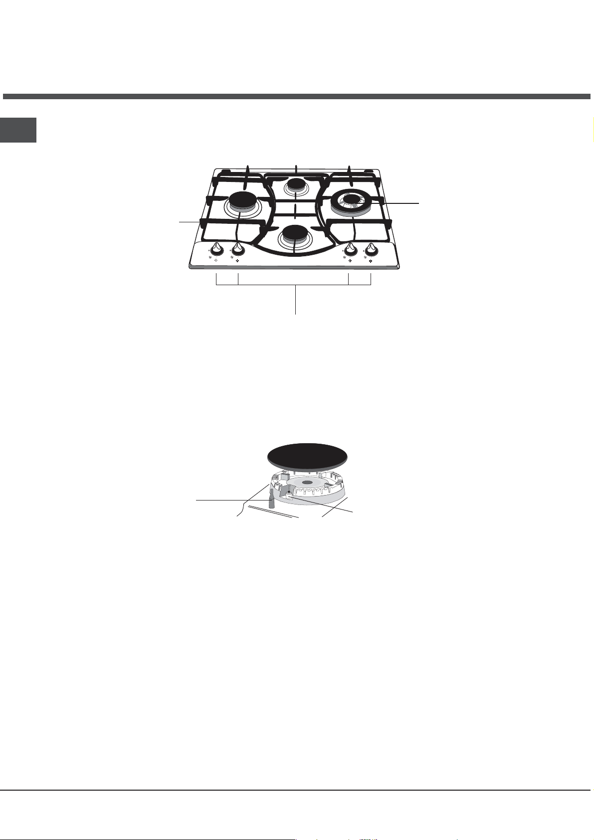
Opis urz¹dzenia, 6
Widok ogólny
Uruchomienie i u¿ytkowanie, 7-8
Praktyczne rady na temat u¿ytkowania palników
Zalecenia i rodki ostro¿noci, 9
Ogólne zasady bezpieczeñstwa
Usuwanie odpadów
Konserwacja i utrzymanie, 10
Od³¹czenie pr¹du elektrycznego
Mycie urz¹dzenia
Konserwacja kurków gazowych
Anomalie i ich usuwanie, 11
Page 2

Instalacja
PL
Wa¿nym jest, aby zachowaæ niniejsz¹ ksi¹¿eczkê instrukcji
dla przysz³ych konsultacji. W razie sprzeda¿y, odsprzedania,
czy przeniesienia, nale¿y upewniæ siê, czy znajduje siê ona
wraz z urz¹dzeniem i odpowiednimi uwagami, aby
poinformowaæ nowego w³aciciela o jego funkcjonowaniu.
Nale¿y uwa¿nie przeczytaæ instrukcjê obs³ugi:
gdy¿
zawiera ona wa¿ne informacje na temat instalacji,
w³aciwego i bezpiecznego u¿ytkowania.
Ustawienie
Opakowania nie s¹ zabawkami dla dzieci i nale¿y je
usun¹æ zgodnie z normami zbierania odpadów (patrz
rodki ostro¿noci i zalecenia).
Instalacja powinna zostaæ wykonana zgodnie z
niniejszymi instrukcjami i przez personel zawodowo do
tego przygotowany. B³êdna instalacja mo¿e
powstaniem szkód wobec osób, zwierz¹t lub rzeczy.
Niniejsze urz¹dzenie mo¿e zostaæ zainstalowane
wy³¹cznie w pomieszczeniach ze sta³¹ wentylacj¹,
zgodnie z zaleceniami obowi¹zuj¹cych norm krajowych.
Nale¿y dochowaæ nastêpuj¹cych warunków:
Pomieszczenie powinn
o posiadaæ system
odprowadzaj¹cy na zewn¹trz gazów spalinowych
sk³adaj¹cy siê z okapu lub wyci¹gu elektrycznego,
uruchamianego automatycznie ka¿dorazowo podczas
uruchomienia urz¹dzenia.
Pomieszczenie powinno posiadaæ funkcjonalny system
dop³ywu powietrza umo¿liwiaj¹cy normalne spalanie.
Dop³yw niezbêdnego
powinien byæ mniejszy ni¿ 2 m
do spalania powietrza nie
3
/h na ka¿dy kW
zainstalowanej mocy.
System mo¿e polegaæ na
bezporednim poborze powietrza
z zewn¹trz budynku przy pomocy
kana³u o przekroju u¿ytecznym
A
przynajmniej 100 cm
zabezpieczonego przed
przypadkowym zalepieniem.
Albo te¿, w sposób poredni, z
przyleg³ych pomieszczeñ
wyposa¿onych w przewód
wentylacyjny jak opisany powy¿ej, a
nie bêd¹cy czêci¹ wspóln¹ dla
ca³ej nieruchomoci ani nie maj¹cy
po³¹czeñ z pomieszczeniami
sypialni lub
w których wystêpuje
zagro¿enie po¿arem.
Skroplone gazy pochodne ropy
naftowej, ciê¿sze od powietrza, opadaj¹ w dó³. Dlatego
pomieszczenia, w których przechowywane s¹ butle GPL
skutkowaæ
2
i
powinny przewidywaæ otwory prowadz¹ce na zewn¹trz
umo¿liwiaj¹ce
sp³ywanie ku do³owi ewentualnych
wycieków gazu. Ponadto butle GPL, niezalezn¿e od tego
czy s¹ puste, czy czêciowo nape³nione, nie powinny byæ
instalowane ani sk³adowane w pomieszczeniach lub
komorach o po³o¿onych poni¿ej poziomu
pod³ogi (piwnice,
itp.). Dobrze jest przechowywaæ w pomieszczeniu jedynie
butle aktualnie u¿ytkowan¹, umocowan¹ w sposób nie
nara¿aj¹cy jej na bezporednie oddzia³ywanie róde³
ciep³a (piece, kominki, piecyki, itp.) mog¹ce doprowadziæ
do wzrostu temperatury powietrza powy¿ej 50°C
.
Zabudowa
P³yty gazowe i mieszane przystosowane s¹ do stopnia
ochrony przed nadmiernym rozgrzaniem typy V, mo¿liwa
jest jednak ich instalacja obok mebli, których wysokoæ
nie przekracza wysokoci p³yty roboczej. W celu
poprawnego zainstalowania p³yty grzewczej
nale¿y
zachowaæ nastêpuj¹ce rodki ostro¿noci:
Meble znajduj¹ce siê obok, a których wysokoæ przekracza
wysokoæ p³yty roboczej, powinny zostaæ odsuniête
przynajmniej na 600 mm od krawêdzi p³yty roboczej.
Okapy powinny byæ zainstalowane zgodnie
z warunkami
wymaganymi podanymi przez instrukcje samych okapów,
jednak w minimalnej odleg³oci 650 mm.
Umieciæ s¹siaduj¹ce z okapem szafki wisz¹ce na
wysokoci minimalne od szczytu 420 mm (patrz
ilustracja).
By p³yta grzewcza mog³a byæ
zainstalowana pod szafk¹
600mm min.
700mm min.
wisz¹c¹, ta ostatnia powinna
znajdowaæ siê w odleg³oci
minimalnej od szczytu
540mm min.
wynosz¹cej 700 mm (patrz
ilustracja).
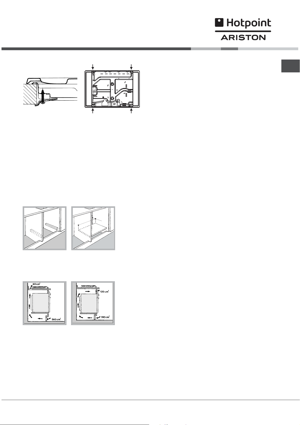
Wnêka na obudowê powinna mieæ wymiary podane na
ilustracji. Przewidziano uchwyty mocuj¹ce
umo¿liwiaj¹ce zamocowanie p³yty na podstawie
posiadaj¹cej gruboæ od 20 do 40 mm. Aby solidnie
zamocowaæ p³yt
ê zaleca siê zastosowanie wszystkich
uchwytów znajduj¹cych siê do dyspozycji.
555 mm
55 mm
475 mm
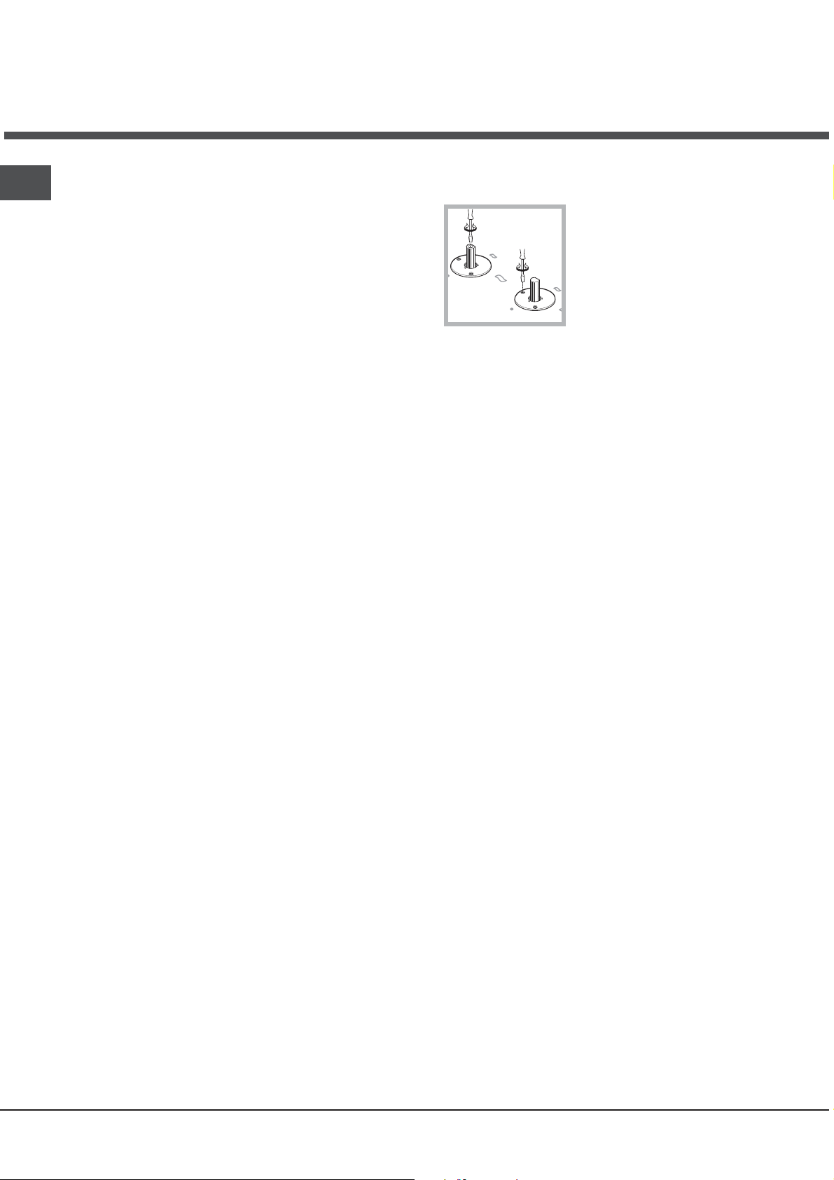
Schemat mocowania uchwytów
Po³o¿enie uchwytu w
stosunku do top H=20mm
Po³o¿enie uchwytu w
stosunku do top H=30mm
2
Page 3
Przód
Ty³Po³o¿enie uchwytu w
stosunku do top H=40mm
Stosowaæ uchwyty zawarte w zestawie akcesoriów
W przypadku, gdy p³yta nie jest zainstalowana na
zabudowanym piekarniku, koniecznym jest
zastosowanie p³yty drewnianej jako izolatora. Powinna
byæ ona zamocowana w odleg³oci minimum 2
dolnej czêci samej p³yty roboczej.
Obieg powietrza
W celu zapewnienia dobrego obiegu powietrza koniecznym
jest usuniêcie tylnej cianki komory. Najlepiej zainstalowaæ
piekarnik w taki sposób, aby wspiera³ siê na dwóch listwach
drewnianych
przynajmniej 45 x 560 mm (patrz ilustracje).
lub na drewnianej desce z przewitem
45 mm.
560 mm.
0 mm od
W przypadku instalacji na piekarniku nie
wyposa¿onym w obieg ch³odz¹cy nale¿y zapewniæ
swobodny przep³yw powietrza w celu w³aciwej
wentylacji.
Pod³¹czenie do sieci elektrycznej
P³yty wyposa¿one w przewód zasilaj¹cy trój¿y³owy
dostosowane s¹ do pracy na pr¹d zmienny przy napiêciu
i czêstotliwoci zasilania wskazanych na tabliczce
znamionowej (umieszczonej w dolnej czêci p³yty).
Przewód uziemienia w sznurze oznaczony jest
¿ó³to-zielonym. W przypadku zainstalowania ponad
piekarnikiem zabudowanym pod³¹czenia elektryczne
p³yty i piekarnika powinny byæ wykonane osobno, tak z
przyczyn bezpieczeñstwa elektrycznego, jak i dla
u³atwienia ewentualnego wyjêcia piekarnika.
kolorem
Pod³¹czenie przewodu zasilaj¹cego do sieci.
Zamocowaæ na przewodzie znormalizowan¹ wtyczkê do
obci¹¿eñ wskazanych na tabliczce znamionowej.
W przypadku bezporedniego pod³¹czenia do sieci
koniecznym jest zainstalowanie pomiêdzy
sieci¹ wy³¹cznika polowego z otwarciem minimalnym
pomiêdzy stykami 3 mm przeznaczonego do obci¹¿eñ i
odpowiadaj¹cego obowi¹zuj¹cym normom (przewód
uziemienia nie powinien byæ przerywany przez
wy³¹cznik). Przewód zasilania powinien byæ umieszczony
w taki sposób, aby w ¿adnym punkcie temperatura
otoczenia nie przekracza³a 50°C.
Instalator odpowiada za poprawnoæ pod³¹czenia
elektrycznego i za zachowanie norm bezpieczeñstwa.
Przed wykonaniem pod³¹czenia nale¿y upewniæ siê, czy:
gniazdko posiada odpowiednie uziemienie i zgodne
jest z obowi¹zuj¹cymi przepisami;
gniazdko jest
maksymalnej mocy urz¹dzenia wskazane na tabliczce
znamionowej;
napiêcie zasilania odpowiada wartociom podanym na
tabliczce znamionowej;
gniazdko musi byæ odpowiednie dla wtyczki urz¹dzenia.
W przeciwnym razie nale¿y wymieniæ gniazdko lub
wtyczkê; nie stosowaæ przed³u¿aczy, ani
Po zainstalowaniu urz¹dzenia przewód elektryczny i
gniazdko powinny byæ ³atwo dostêpne.
Kabla nie wolno zginaæ ani przyciskaæ.
Przewód elektryczny musi byæ okresowo sprawdzany i
wymieniany jedynie przez autoryzowanych techników
(patrz Serwis).
Producent odrzuca
przypadku, gdy niniejsze zasady nie bêd¹ przestrzegane.
w stanie wytrzymaæ obci¹¿enie
wszelk¹ odpowiedzialnoæ w
urz¹dzeniem a
rozga³êników
Pod³¹czenie gazu
Pod³¹czenie urz¹dzenia do przewodów lub butli gazowej
powinno zostaæ wykonane zgodnie z zaleceniami
obowi¹zuj¹cych norm krajowych dopiero po upewnieniu
siê, ¿e jest ono wyregulowane do pracy z rodzajem gazu,
którym bêdzie zasilane. W przeciwnym wypadku
onaæ czynnoci wskazane w paragrafie
wyk
Dostosowanie do ró¿nych rodzajów gazu W przypadku
zasilania p³ynnym gazem z butli, stosowaæ regulatory
cinienia zgodne z obowi¹zuj¹cymi normami krajowymi.
W celu uzyskania pewnoci pracy, odpowiedniego zu¿ycia
energii i
siê czy cinienie zasilania mieci siê w granicach
zalecanych w tabeli 1 Charakterystyki palników i dysz.
Pod³¹czenie przewodem sztywnym (mied lub stal)
Pod³¹czenie do urz¹dzenia gazowego po
wykonane w taki sposób, aby nie powodowaæ ¿¹dnych
naprê¿eñ urz¹dzenia.
Na przewodzie zasilaj¹cym urz¹dzenie znajduje siê
ruchome z³¹cze kolankowe L , którego szczelnoæ
zapewniona jest uszczelk¹. W przypadku gdyby okaza³o
siê, ¿e koniecznym jest obrócenie kolanka nale¿y
zwiêkszenia trwa³oci urz¹dzenia nale¿y upewniæ
winno byæ
PL
3
Page 4
PL
obowi¹zkowo wymieniæ uszczelkê (na wyposa¿eniu
urz¹dzenia). Z³¹cze wejciowe gazu do urz¹dzenia jest
gwintowane gwintem gazowym 1/2 walcowym mêskim.
Pod³¹czenie z przewodem elastycznym ze stali
nierdzewnej o
z³¹czami.
Z³¹cze wejciowe gazu do urz¹dzenia jest gwintowane
gwintem gazowym 1/2 walcowym mêskim.
U¿ycie przewodów tego rodzaju powinno byæ wykonane
w ten sposób, aby ich d³ugoæ,
maksymalnego rozszerzenia nie przekracza³a 2000 mm.
Po wykonaniu pod³aczenia upewnic siê, czy metalowy
przewód elastyczny nie styka siê z elementami
ruchomymi, ani nie jest przygnieciony.
Stosowaæ wy³¹cznie przewody i uszczelki zgodne z
obowi¹zuj¹cymi normami krajo
Kontrola szczelnoci
Po zakoñczeniu instalacji skontrolowaæ szczelnoæ
wszystkich z³¹cz stosuj¹c w tym celu wodny rozwór
myd³a, nigdy p³omieñ.
Dostosowanie do ró¿nych rodzajów gazu
W celu dostosowania p³yty
do którego jest przystosowana (wskazanego na etykiecie w
dolnej czêci p³yty lub na opakowaniu), nale¿y wymieniæ
dysze palników wykonuj¹c nastêpuj¹ce czynnoci:
1. zdj¹æ kratkê z p³yty i wykrêciæ palniki z ich gniazd
.odkrêciæ dysze pos³uguj¹c siê kluczem rurowym 7mm
2
i wymieniæ je na nowy rodzaj przystosowany do
nowego rodzaju gazu (patrz tabela 1 Charakterystyki
palników i dysz).
3. ponownie zmontowaæ czêci w kolejnoci odwrotnej.
zakoñczenie czynnoci wymieniæ poprzedni¹
4. na
etykietê regulacyjna na now¹, odpowiadaj¹ca nowemu
paliwu, dostepn¹ w naszych centrach obs³ugi
technicznej.
pe³nych ciankach z gwintowanymi
w warunkach
wymi.
do innego rodzaju gazu ni¿ ten,
Regulacja minimów
1. Ustawiæ kurek w po³o¿eniu minimum;
2.Zdj¹
siê rub¹ regulacyjna
znajduj¹ca siê wewn¹trz lub
obok osi kurka uzyskaæ
najmniejszy regularny p³omieñ.
3. Upewniæ siê, czy podczas szybkiego obracania
pokrêt³em z po³o¿enia maksymalnego do
minimalnego nie wystêpuje ganiêcie palników.
4. W urz¹dzeniach wyp
zabezpieczaj¹ce (termopara) w przypadku
niezadzia³ania urz¹dzenia z palnikami ustawionymi
na minimum nale¿y zwiêkszyæ minimalne przep³ywy
przy pomocy ruby regulacyjnej.
5. Po zakoñczeniu regulacji ponownie za³o¿yæ plomby
lakowe, lub z równorzêdnego materia³u, umieszczone
na obejciu
W przypadku gazu p³ynnego ruba regulacyjna
powinna byæ dokrêcona do koñca.
Po zakoñczeniu operacji nale¿y wymieniæ poprzednia
etykietê nastawieñ na etykietê odpowiadaj¹c¹ nowemu
gazowi u¿ytkowemu, dostêpn¹ w naszych centrach
obs³ugi technicznej.
W sytuacji, gdy cinienie
ró¿ne (lub zmienne) od przewidywanego, koniecznym
jest zainstalowanie na przewodach doprowadzaj¹cych
regulatora cinienia (zgodnie zobowi¹zuj¹c¹ norm¹
krajow¹ regulatory kana³owe dla gazu).
.
osa¿onych w urz¹dzenie
æ pokrêt³o i pos³uguj¹c
stosowanego gazu stanie siê
Regulacja powietrza pierwotnego palników
Palniki nie wymagaj¹ ¿adnej regulacji powietrza
pierwotnego.
4
Page 5
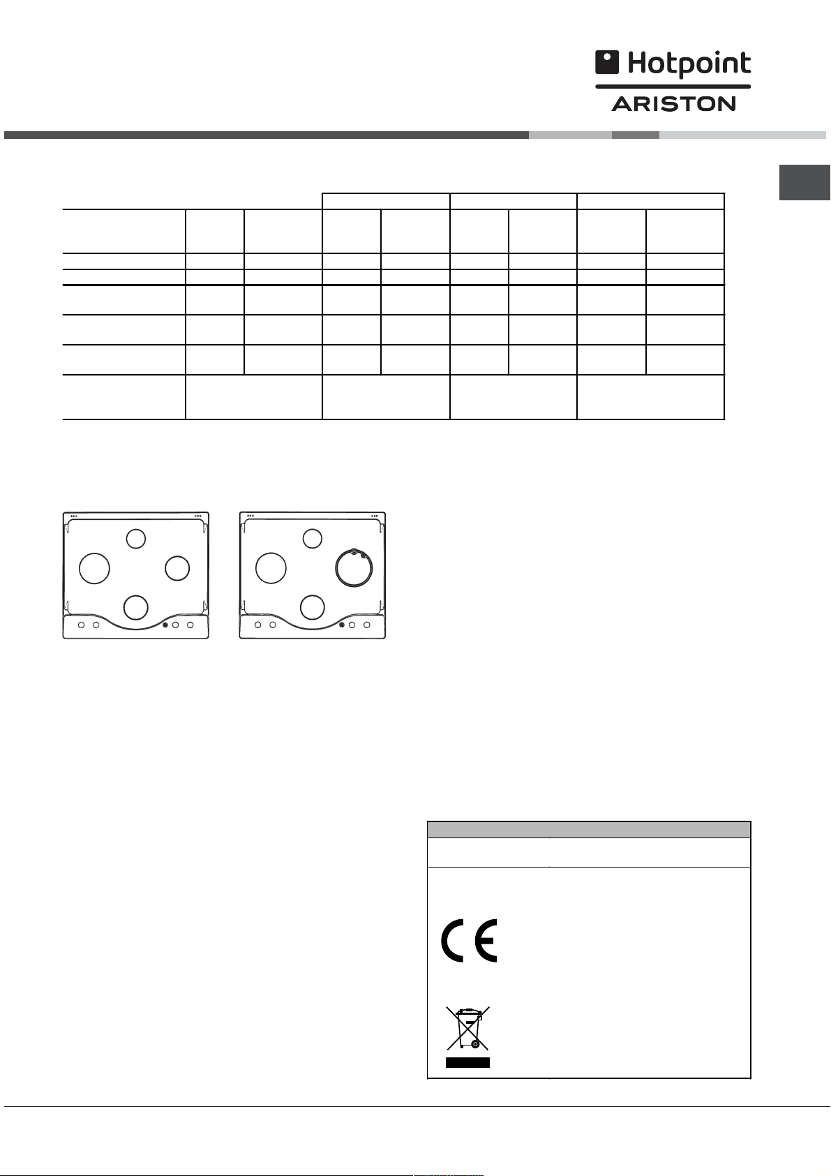
Charakterystyki palników oraz dysz
p
Tabela 1 (dla Polski)
Palnik
rednica
(w mm)
Moc cieplna
(p.c.i.*)
kW
Dysza
1/100
(w mm)
redni (RR) 100 2.5 110 265 170 368 80 197
Du¿y (R) 100 2.7 116 286 180 398 86 213
Pó³szybki (redni)
(S)
Pomocniczy (ma³y)
(A)
Potrójn a korona
(TC)
75 1.6 96 169 140 236 64 126
55 0.9 71 95 106 133 50 71
130 3.0 126 318 190 442 91 236
minimalne (mbar)
Cinienia zasilania
nominalne (mbar)
maksymalne (mbar)
* A 15°C e 1013 mbar – gaz suchy
GZ50 p.c.i. = 35.9 MJ/m
GZ35 p.c.i. = 25.8 MJ/m
GPB
.c.i. = 123.6 MJ/m3
3
3
GZ50
Przep³yw*
l/godz
16
20
25
Dysza
1/100
(w mm)
GZ35
Przep³yw*
l/godz
10
13
16
Dysza
1/100
(w mm)
GPB-B
Przep³yw*
g/godz
29
36
44
PL
A
R
S
S
RR
A
S
PH 640 MS U/HA PH 640 MST U R/HA
TC
TABLICZKA ZNAMIONOWA
Pod³¹czenia
elektryczne
patrz tabliczka znamionowa
Niniejsze urz¹dzenie zosta³o
wyprodukowane zgodnie z
nastêpuj¹cymi dyrektywami
unijnymi:
-2006/95/CEE z dn. 12/12/06 (o
Niskim Napiêciu) wraz z
póniejszymi zmianami
-89/336/CEE z dn. 03/05/89 (o
Zgodnoci Elektromagnetycznej)
wraz z póniejszymi zmianami
- 93/68/CEE z dn. 22/07/93 wraz z
póniejszymi zmianami.
-90/336/
CEE
z 03/05/89 (Gaz) wraz
z póniejszymi zmianami.
-2002/96/EC
5
Page 6
Opis
urz¹dzenia
PL
Widok ogólny
Palniki gazowe
Kratki do ustawiania
naczyń do gotowania
Pokrętła sterujące
palników gazowych
Ur z¹dzenia
zabezpieczaj¹ce
Palniki gazowe posiadaj¹ ró¿ne wymiary i moce.
Nale¿y wybraæ najbardziej odpowiedni dla rednicy
u¿ywanego naczynia.
Pokrêt³a sterowania palnikami gazowymi do
regulowania p³omienia lub mocy.
wieca zap³onowa palników
gazowych
wieca zap³onowa palników gazowych
umo¿liwia automatyczna zapalenie wybranego
palnika.
Urz¹dzenie zabezpieczaj¹ce w przypadku
przypadkowego zganiêcia p³omienia przerywa
wydobywanie siê gazu.
6
Page 7

Uruchomienie i
u¿ytkowanie
Dla ka¿dego z pokrête³ wskazane jest po³o¿enie palnika
gazowego lub p³yty elektrycznej* odpowiadaj¹cych im.
Palniki gazowe
Wybrany palnik mo¿e byæ regulowany odpowiednim
pokrêt³em w nastêpuj¹cy sposób:
Wy³¹czony
Maksimum
Minimum
W celu zapalenia którego z palników zbli¿yæ do niego
p³omieñ lub zapalarkê, wdusiæ do koñca i obróciæ
odpowiednim pokrêt³em w kierunku przeciwnym do
wskazówek zegara do po³o¿enia maksymalnej mocy.
W modelach wyposa¿onych w urz¹dzenia
zabezpieczaj¹ce koniecznym jest przytrzymaæ wduszone
pokrêt³o przez oko³o 2-3 sekundy a¿ rozgrzeje siê
urz¹dzenia podtrzymuj¹ce automatycznie zapalony
p³omieñ.
W modelach wyposa¿onych w wiecê zap³onow¹, aby
zapaliæ wybrany palnik wdusiæ do koñca i obróciæ
odpowiednie pokrêt³o w kierunku przeciwnym do
wskazówek zegara a¿ do po³o¿enia maksymalnej mocy i
przytrzymaæ wduszone a¿ do nast¹pienia zap³onu.
Zalecenia praktyczne u¿ytkowania
palników
W celu uzyskania maksymalnej wydajnoci nale¿y
pamiêtaæ, co nastêpuje:
stosowaæ naczynia odpowiednie dla ka¿dego z
palników (patrz tabela) w celu unikniêcia
wychodzenia p³omieni poza pole dna naczyñ.
stosowaæ zawsze naczynia o dnie p³askim i z
przykrywk¹.
w chwili zagotowania siê obróciæ pokrêt³o do
po³o¿enia minimum.
Palnik
Szybki (R) 24 - 26
Szybki zm niejszony (RP) 22 - 24
Pó³ szybki (S) 16 - 20
Pomocniczy (A) 10 - 14
Potrójna korona (TC) 24 - 26
¸ Úrednica naczyñ (cm)
PL
W przypadku przypadkowego zganiêcia p³omienia
palnika, zakrêciæ pokrêt³o steruj¹ce i ponowiæ próbê
zapalenia po up³ywie przynajmniej 1 minuty.
Aby zgasiæ palnik nale¿y obróciæ pokrêt³o zgodnie z
ruchem zegara a¿ do zatrzymania (odpowiadaj¹cego
symbolowi ).
7
Page 8

Zalecenia i rodki
ostro¿noci
PL
Urz¹dzenie zosta³o zaprojektowane i
wyprodukowane zgodnie z miêdzynarodowymi
przepisami bezpieczeñstwa. Maj¹c na wzglêdzie
Wasze bezpieczeñstwo podajemy Wam poni¿sze
zalecenia, które nale¿y uwa¿nie przeczytaæ.
Ogólne zasady bezpieczeñstwa
Niniejsze urz¹dzenie jest urz¹dzeniem
przeznaczonym do zabudowy klasy 3.
Urz¹dzenia gazowe wymagaj¹, dla swego
poprawnego dzia³ania, regularnej wymiany
powietrza. nale¿y upewniæ siê, czy podczas ich
instalowania przestrzegane by³y wymagania
zawartye w odpowiednim paragrafie dotycz¹cym
Ustawienia.
Zalecenia maj¹ zastosowanie wy³¹cznie dla
krajów przeznaczenia, których symbole znajduj¹
siê w instrukcji
fabrycznym.
Niniejsze urz¹dzenie przeznaczone jest do
nieprofesjonalnych zastosowañ domowych.
Nie nale¿y instalowaæ urz¹dzenia poza domem,
nawet jeli miejsce to jest chronione daszkiem, gdy¿
wystawienie urz¹dzenia na dzia³anie deszczu i burz
jest bardzo niebezpieczne.
W celu przenoszenia urz¹dzenia nale¿y zawsze
korzystaæ z odpowiednich uchwytów umocowanych
po bokach piekarnika.
Nie dotykaæ urz¹dzenia stoj¹c przy nim boso lub
gdy rêce czy stopy s¹ mokre lub wilgotne.
Urz¹dzenie przeznaczone jest do gotowania
potraw jedynie przez osoby doros³e i zgodnie z
instrukcjami zawartymi w niniejszej ksi¹¿eczce.
Nale¿y uwa¿aæ, aby przewody zasilaj¹ce
pozosta³e urz¹dzenia domowe nie styka³y siê z
rozgrzanymi elementami piekarnika.
Nie zas³aniaæ otworów wentylacyjnych i
odprowadzaj¹cych ciep³o.
Nale¿y zawsze sprawdziæ, czy pokrêt³a znajduj¹
siê w pozycji l/
u¿ywane;
Nie wyci¹gaæ wtyczki z gniazdka trzymaj¹c kabel
ale tylko trzymaj¹c za wtyczkê.
Nie czyciæ ani nie wykonywaæ czynnoci
konserwacyjnych bez uprzedniego od³¹czenia
wtyczki od sieci elektrycznej.
W razie usterki nie nale¿y w ¿adnym wypadku
siêgaæ do wewnêtrznych czêci urz¹dzenia, w celu
usi³owania jego naprawy. Skontaktowaæ siê z
Serwisem (patrz Serwis).
oraz na tabliczce z numerem
¡ , kiedy urz¹dzenie nie jest
Nale¿y upewniaæ siê, czy uchwyty garnków s¹
zwrócone zawsze w kierunku wnêtrza p³yty
grzewczej aby unikn¹æ ich przypadkowego
potr¹cenia.
Nie zamykaæ szklanej pokrywy (jeli jest na
wyposa¿eniu) gdy palniki gazowe lub p³yta
grzewcza s¹ jeszcze rozgrzane.
Nie pozostawiaæ w³¹czonej elektrycznej p³yty
grzewczej bez naczyñ.
Nie stosowaæ garnków niestabilnych lub
odkszta³conych.
Nie jest przewidziane aby urz¹dzenie by³o
u¿ywane przez osoby (równie¿ dzieci) niesprawne
fizycznie i umys³owo, przez osoby bez
dowiadczenia lub bez znajomoci urz¹dzenia
chyba, ze pod nadzorem osoby odpowiedzialnej
za jego bezpieczeñstwo jak równie¿ bez
otrzymania instrukcji wstêpnych co do jego
u¿ytku.
Usuwanie odpadów
Usuwanie materia³ów opakowaniowych:
dostosowaæ siê do lokalnych przepisów; w ten
sposób opakowanie bêdzie mog³o zostaæ
odzyskane.
Europejska Dyrektywa 2002/96/EC dotycz¹ca
Zu¿ytych Elektrycznych i Elektronicznych Urz¹dzeñ
(WEEE) zak³ada zakaz pozbywania siê starych
urz¹dzeñ domowego u¿ytku jako nieposortowanych
mieci komunalnych. Zu¿yte urz¹dzenia musz¹ byæ
osobno zbierane i sortowane w celu
zoptymalizowania odzyskania oraz ponownego
przetworzenia pewnych komponentów i materia³ów.
Pozwala to ograniczyæ zanieczyszczenie
rodowiska i pozytywnie wp³ywa na ludzkie zdrowie.
Przekrelony symbol kosza umieszczony na
produkcie przypomina klientowi o obowi¹zku
specjalnego sortowania.
Konsumenci powinni kontaktowaæ siê z w³adzami
lokalnymi lub sprzedawc¹ w celu uzyskania
informacji dotycz¹cych postêpowania z ich zu¿ytymi
urz¹dzeniami gospodarstwa domowego.
8
Page 9

Konserwacja i utrzymanie
Od³¹czenie pr¹du elektrycznego
Przed napraw¹ od³¹czyæ urz¹dzenie od sieci zasilania
elektrycznego.
Mycie urz¹dzenia
Wystrzegaæ siê stosowania myj¹cych rodków
ciernych lub koroduj¹cych, takich jak odplamiacze i
produktu odrdzewiaj¹ce, detergentów w proszku oraz
g¹bek o powierzchni cieraj¹cej. mog¹ w sposób
nieusuwalny zarysowaæ powierzchniê.
Nigdy nie stosowaæ oczyszczaczy parowych lub
cinieniowych do czyszczenia urz¹dzenia.
W ramach zwyk³ej konserwacji wystarczy
przemywanie p³yty wilgotna g¹bk¹ i przetarcie
papierowym rêcznikiem kuchennym..
Elementy ruchome palników powinny byæ
przemywane czêsto ciep³a wod¹ i rodkiem
myj¹cym z uwzglêdnieniem koniecznoci usuwania
ewentualnych skrzeplin.
Konserwacja kurków gazowych
PL
Z up³ywem czasu mo¿e pojawiæ siê kurek blokuj¹cy siê
lub z trudem obracaj¹cy siê, dlatego mo¿e okazaæ siê
konieczn¹ wymiana kurka.
Czynnoæ ta winna byæ wykonana przez
autoryzowanego technika producenta.
W przypadku p³yt wyposa¿onych w automatyczne
zapalanie, nale¿y przewidzieæ czêste i dok³adne
oczyszczanie czêci koñcówek zapalarek
elektronicznych, oraz sprawdzaæ, czy otwory
wylotowe gazu nie s¹ zatkane;
Stal nierdzewna mo¿e siê poplamiæ, jeli bêdzie
przez d³u¿szy czas w kontakcie z wod¹ o du¿ej
zawartoci wapnia lub z agresywnymi
detergentami (zawieraj¹cymi fosfor). Zaleca siê
obficie sp³ukaæ i osuszyæ po wymyciu. Ponadto
nale¿y osuszy
æ ewentualne wycieki wody.
9
Page 10

PL
Anomalie i rodki
zaradcze
Mo¿e siê zdarzyæ, ¿e p³yta nie dzia³a lub le dzia³a. Zanim wezwiecie serwis naprawczy, zobaczmy razem, co
mo¿na zrobiæ. Przede wszystkim nale¿y sprawdziæ, czy nie wystêpuj¹ przerwy w sieci zasilania gazem lub
pr¹dem elektrycznym, a zw³aszcza czy zawory gazowe przed kuchenk¹ s¹ otwarte.
Palnik nie zapala siê lub p³omieñ jest
nierównomierny.
P³omieñ nie zostaje zapalony w wersjach z
zabezpieczeniem.
Palnik w po³o¿eniu minimum nie pali siê.
Naczynia s¹ niestabilne
Jeli, niezale¿nie od wszelkich kontroli p³yta nie dzia³a, a niedogodnoæ stwierdzona przez was nie ustêpuje,
nale¿y wezwaæ centrum pomocy technicznej. Nale¿y podaæ:
model urz¹dzenia (Mod.)
numer seryjny (S/N)
Te ostatnie informacje znajduj siê na tabliczce znamionowej umieszczonej na urz¹dzeniu i/lub na jego opakowaniu.
S¹ zatkane otwory wylotowe gazu w palniku.
Zamontowane s¹ poprawnie wszystkie czêci ruchome
wchodz¹ce w sk³ad palnika.
Wystêpuj¹ przeci¹gi w s¹siedztwie p³yty kuchennej.
Nie wdusilicie do koñca pokrêt³a
Nie przytrzymalicie wduszonego do koñca pokrêt³a przez
czas wystarczaj¹cy do uruchomienia urz¹dzenia
zabezpieczaj¹cego.
S¹ pozatykane otwory wylotowe gazu w pobli¿u
urz¹dzenia zabezpieczaj¹cego.
S¹ pozatykane otwory wylotowe gazu.
Wystêpuj¹ przeci¹gi w s¹siedztwie p³yty.
Regulacja minimum nie jest w³aciwa.
Dna garnków s¹ dok³adnie równe.
Garnek jest ustawiony na rodku palnika lub p³yty
elektrycznej.
Kratki zosta³y odwrócone.
Zwracajcie siê wy³¹cznie do upowa¿nionego Serwisu Technicznego i domagajcie siê zainstalowania
wy³¹cznie oryginalnych czêci zamiennych.
10
Page 11

Operating Instructions
Contents
Installation, 12-15
PL
Polski, 1
GB
English,11
Positioning
Electrical connection
Gas connection
Data plate
Burner and nozzle specifications
Description of the appliance, 16
Overall view
Start-up and use, 17
Practical advice on using the burners
Precautions and tips, 18
General safety
Disposal
HOB
GB
PH640MS U/HA
PH640MST U/HA
PH640MST U R/HA
Maintenance and care, 19
Switching the appliance off
Cleaning the appliance
Gas tap maintenance
Troubleshooting, 20
Page 12

Installation
A
Examples of ventilation holes
for comburant air.
GB
Before operating your new appliance please read this
instruction booklet carefully. It contains important information
for safe use, installation and care of the appliance.
Please keep these operating instructions for future
reference. Pass them on to possible new owners of the
appliance.
Positioning
Keep packaging material out of the reach of children. It
can become a choking or suffocation hazard (see
Precautions and tips).
The appliance must be installed by a qualified professional
according to the instructions provided. Incorrect installation
may cause harm to people and animals or may damage
property.
This unit may be installed and used only in permanently
ventilated rooms in accordance with British Standard Codes
Of Practice: B.S. 6172 / B.S. 5440, Par. 2 and B.S. 6891
Current Editions. The following requirements must be
observed:
The room must be equipped with an air extraction system
that expels any combustion fumes. This may consist of a
hood or an electric fan that automatically starts each time
the appliance is switched on.
also be equipped with vents to allow gas to escape in the
event of a leak. As a result LPG cylinders, whether
partially or completely full, must not be installed or stored
in rooms or storage areas that are below ground level
(cellars, etc.). It is advisable to keep only the cylinder
being used in the room, positioned so that it is not
subject to heat produced by external sources (ovens,
fireplaces, stoves, etc. ) which could raise the
temperature of the cylinder above 50°C.
Fitting the appliance
Gas and mixed hobs are manufactured with type X degree
protection against overheating. The following precautions
must be taken when installing the hob:
Kitchen cabinets adjacent to the appliance and taller
than the top of the hob must be at least 600 mm from the
edge of the hob.
Hoods must be installed according to their relative
installation instruction manuals and at a minimum
distance of 650 mm from the hob.
Place the wall cabinets adjacent to the hood at a
minimum height of 420 mm from the hob (see figure).
If the hob is installed beneath a
wall cabinet, the latter must be
600mm min.
situated at a minimum of 700 mm
above the hob (see figure).
700mm min.
540mm min.
In a chimney stack or branched flue.
(exclusively for cooking appliances)
Directly to
the Outside
The room must also allow proper air circulation, as air is
needed for combustion to occur normally. The flow of air
must not be less than 2 m
3
/h per kW of installed power.
The air circulation system may
take air directly from the outside
by means of a pipe with an inner
cross section of at least 100 cm
the opening must not be
vulnerable to any type of
blockages.
Adjacent
Room
Room to be
Vented
The system can also provide the
air needed for combustion
indirectly, i.e. from adjacent rooms
fitted with air circulation tubes as
described above. However, these
Enlarging the ventilation slot
between window and floor.
rooms must not be communal
rooms, bedrooms or rooms that
may present a fire hazard.
Liquid petroleum gas sinks to the floor as it is heavier
than air. Therefore, rooms containing LPG cylinders must
The installation cavity should have the dimensions
indicated in the figure.
Fastening hooks are provided, allowing you to fasten the
hob to tops that are between 20 and 40 mm thick. To
ensure the hob is securely fastened to the top, we
recommend you use all the hooks provided.
555 mm
2
;
55 mm
475 mm
Hook fastening diagram
Hooking position Hooking position
for top H=20 mm for top H=30 mm
12
Page 13

Front
Hooking position Back
for top H=40 mm
Use the hooks contained in the accessory pack
Where the hob is not installed over a built-in oven, a
wooden panel must be installed as insulation. This must
be placed at a minimum distance of 20 mm from the
lower part of the hob.
Ventilation
To ensure adequate ventilation, the back panel of the
cabinet must be removed. It is advisable to install the oven
so that it rests on two strips of wood, or on a completely flat
surface with an opening of at least 45 x 560 mm (see
diagrams).
45 mm
.
m
m
0
6
5
.
When installing the cooktop above a built-in oven
without forced ventilation, ensure that there are air
inlets and outlets for ventilating the interior of the
cabinet adequately.
Electrical connection
Hobs equipped with a three-pole power supply cable are
designed to operate with alternating current at the voltage
and frequency indicated on the data plate (this is located on
the lower part of the appliance). The earth wire in the cable
has a green and yellow cover. If the appliance is to be
installed above a built-in electric oven, the electrical
connection of the hob and the oven must be carried out
separately, both for electrical safety purposes and to make
extracting the oven easier.
Connecting the supply cable to the mains
Install a standardised plug corresponding to the load
indicated on the data plate.
The appliance must be directly connected to the mains using
an omnipolar circuit-breaker with a minimum contact opening
of 3 mm installed between the appliance and the mains. The
circuit-breaker must be suitable for the charge indicated and
must comply with current electrical regulations (the earthing
wire must not be interrupted by the circuit-breaker). The
supply cable must not come into contact with surfaces with
temperatures higher than 50°C.
The installer must ensure that the correct electrical
connection has been made and that it is compliant with
safety regulations.
Before connecting to the power supply, make sure that:
The appliance is earthed and the plug is compliant with
the law.
The socket can withstand the maximum power of the
appliance, which is indicated on the data plate.
The voltage is in the range between the values indicated
on the data plate.
The socket is compatible with the plug of the appliance. If
the socket is incompatible with the plug, ask an
authorised technician to replace it. Do not use extension
cords or multiple sockets.
Once the appliance has been installed, the power supply
cable and the electrical socket must be easily accessible.
The cable must not be bent or compressed.
The cable must be checked regularly and replaced by
authorised technicians only (see Assistance
).
The manufacturer declines any liability should these safety
measures not be observed.
Gas connection
The appliance should be connected to the main gas supply
or to a gas cylinder in compliance with current national
regulations. Before carrying out the connection, make sure
the cooker is compatible with the gas supply you wish to
use. If this is not the case, follow the instructions indicated in
the paragraph Adapting to different types of gas.
When using liquid gas from a cylinder, install a pressure
regulator which complies with current national regulations.
Check that the pressure of the gas supply is consistent
with the values indicated in Table 1 (Burner and nozzle
specifications). This will ensure the safe operation and
longevity of your appliance while maintaining efficient
energy consumption.
Connection with a rigid pipe (copper or steel)
Connection to the gas system must be carried out in such
a way as not to place any strain of any kind on the
appliance.
There is an adjustable L-shaped pipe fitting on the
GB
13
Page 14

GB
appliance supply ramp and this is fitted with a seal in
order to prevent leaks. The seal must always be replaced
after rotating the pipe fitting (seal provided with
appliance). The gas supply pipe fitting is a threaded 1/2
gas cylindrical male attachment.
Connecting a flexible jointless stainless steel pipe to a
threaded attachment
The gas supply pipe fitting is a threaded 1/2 gas cylindrical
male attachment.
These pipes must be installed so that they are never longer
than 2000 mm when fully extended. Once connection has
been carried out, make sure that the flexible metal pipe
does not touch any moving parts and is not compressed.
Only use pipes and seals that comply with current national
regulations.
Checking the tightness of the connection
When the installation process is complete, check the pipe
fittings for leaks using a soapy solution. Never use a flame.
Adapting to different types of gas
To adapt the hob to a different type of gas other than default
type (indicated on the rating plate at the base of the hob or
on the packaging), the burner nozzles should be replaced
as follows:
1. Remove the hob grids and slide the burners off their
seats.
2. Unscrew the nozzles using a 7 mm socket spanner, and
replace them with nozzles for the new type of gas (see
table 1 Burner and nozzle characteristics).
3. Reassemble the parts following the above procedure in
the reverse order.
4. Once this procedure is finished, replace the old rating
sticker with one indicating the new type of gas used.
Sticker are available from any of our Service Centres.
3. Having adjusted the flame to the required low setting,
while the burner is alight, quickly change the position of
the knob from minimum to maximum and vice versa
several times, checking that the flame does not go out.
4. Some appliances have a safety device (thermocouple)
fitted. If the device fails to work when the burners are
set to the low flame setting, increase this low flame
setting using the adjusting screw.
5. Once the adjustment has been made, replace the seals
on the by-passes using sealing wax or a similar
substance.
If the appliance is connected to liquid gas, the regulation
screw must be fastened as tightly as possible.
Once this procedure is finished, replace the old rating
sticker with one indicating the new type of gas used.
Stickers are available from any of our Service Centres.
Should the gas pressure used be different (or vary slightly)
from the recommended pressure, a suitable pressure
regulator must be fitted to the inlet pipe (in order to comply
with current national regulations).
Adjusting the burners primary air :
Does not require adjusting.
Setting the burners to minimum:
1. Turn the tap to the low flame position.
2. Remove the knob and adjust the adjustment screw,
which is positioned in or next to the tap pin, until the
flame is small but steady.
14
DATA PLATE
Electrical
connections
see data plate
This appliance conforms to the
following European Economic
Community directives:
-2006/95/EEC dated 12/12/06
(Low Voltage) and subsequent
amendments
- 89/336/EEC dated 03/05/89
(Electromagnetic Compatibility)
and subsequent amendments
- 93/68/EEC dated 22/07/93 and
subsequent amendments.
- 90/336/EEC dated 29/06/90
(Gas) and subsequent
amendments.
- 2002/96/EC
Page 15

Burner and nozzle specifications
Table 1 Natural Gas GZ50 Natural Gas GZ35 GPB-B
GB
Burner Diameter
(mm)
Thermal power
(p.c.i.*)
Nozzle
1/100
Flow*
l/h
Nozzle
1/100
Flow*
l/h
Nozzle
1/100
Flow*
g/h
kW (mm) (mm) (mm)
Reduced Fast
(Large)(RR)
100 2.5 110 265 170 368 80 197
Fast (Large)(R) 100 2.7 116 286 180 398 86 213
Semi Fast
(Medium)(S)
Auxiliary
(Small)(A)
Triple Crown
(TC)
Supply
Pressures
75 1.6 96 169 140 236 64 126
55 0.9 71 95 106 133 50 71
130 3.0 126 318 190 442 91 236
Minumum (mbar)
Nominal (mbar)
Maximum (mbar)
16
20
25
10
13
16
29
36
44
* A 0°C e 1013 mbar-dry gas
GZ 50 p.c.i. 35.9 MJ/m³
GZ 35 p.c.i. 25.8 MJ/m³
GPB-B p.c.i. 123.6 MJ/m³
A
R
S
PH 640 MS U/HA PH 640 MST U R/HA
S
RR
A
S
TC
15
Page 16

Description of the
appliance
GB
Overall v iew
GAS BURNERS
Support Grid for
COOKWARE
Control Knobs for
GAS BURNERS
SAFETY
DEVICES *
GAS BURNERS differ in size and power. Use the
diameter of the cookware to choose the most
appropriate burner to cook with.
Control Knobs for GAS BURNERS adjust the
power or the size of the flame.
Ignition for
GAS BURNERS *
GAS BURNER ignition enables a specific burner
to be lit automatically.
SAFETY DEVICE stops the gas flow if the flame
is accidentally extinguished.
16
Page 17

Start-up and use
The position of the corresponding gas burner or
electric hotplate* is shown on every knob.
Gas burners
Each burner can be adjusted to one of the following
settings using the corresponding control knob:
Off
Maximum
Minimum
To light one of the burners, hold a lit match or lighter
near the burner and, at the same time, press down
and turn the corresponding knob anti-clockwise to the
maximum setting.
Since the burner is fitted with a safety device, the
knob should be pressed for approximately 2-3
seconds to allow the automatic device keeping the
flame alight to heat up.
Some models are equipped with an ignition switch
incorporated into the control knob. If this is the case,
the ignitor is present, but not the switch (the
symbol is located near each knob).
To light a burner, simply press the corresponding
knob all the way in and then turn it in the counterclockwise direction to the "High" setting, keeping it
pressed in until the burner lights.
Practical advice on using the burners
GB
To ensure the burners operate efficiently:
Use appropriate cookware for each burner (see
table) so that the flames do not extend beyond
the bottom of the cookware.
Always use cookware with a flat base and a cover.
When the contents of the pan reach boiling point,
turn the knob to minimum.
Burner ø Cookware Diameter (cm)
Fast (R) 24 – 26
Reduced Fast (RR) 22 – 24
Semi Fast (S) 16 – 20
Auxiliary (A) 10 – 14
Triple Crown (TC) 24 – 26
If a flame is accidentally extinguished, turn off the
control knob and wait for at least 1 minute before
trying to relight it.
To switch off the burner, turn the knob in a clockwise
direction until it stops (when reaches the position).
17
Page 18

Precautions and tips
GB
This appliance has been designed and
manufactured in compliance with international safety
standards. The following warnings are provided for
safety reasons and must be read carefully.
General safety
This is a class 3 built-in appliance.
Gas appliances require regular air exchange to
maintain efficient operation. When installing the
hob, follow the inst
paragraph on Positioning the appliance.
These instructions are only valid for the
countries whose symbols appear in t
and on the serial number plate.
The appliance was designed for domestic use
inside the home and is not intended for commercial
or industrial use.
The appliance must not be installed outdoors, even
in covered areas. It is extremely dangerous to leave
the appliance exposed to rain and storms.
Do not touch the appliance with bare feet or with
wet or damp hands and feet.
The appliance must be used by adults only, to cook
food according to the instructions in this manual.
Ensure that the power supply cables of other
electrical appliances do not come into contact with
the hot parts of the oven.
The openings used for ventilation and dispersion of
heat must never be covered.
Always make sure the knobs are in the l/
position when the appliance is not in use.
When unplugging the appliance always pull the plug
from the mains socket, do not pull on the cable.
Never carry out any cleaning or maintenance work
without having detached the plug from the mains.
ructions provided in the
he manual
¡
Always make sure that pan handles are turned
towards the centre of the hob in order to avoid
accidental burns.
Do not close the glass cover (if present) when the
gas burners are still hot.
Do not use unstable or deformed pans.
The appliance should not be operated by people
(including children) with reduced physical,
sensory or mental capacities, by inexperienced
individuals or by anyone who is not familiar with
the product. These individuals should, at the very
least, be supervised by someone who assumes
responsibility for their safety or receive
preliminary instructions relating to the operation of
the appliance.
Disposal
When disposing of packaging material: observe
local legislation so that the packaging may be
reused.
The European Directive 2002/96/EC on Waste
Electrical and Electronic Equipment (WEEE),
requires that old household electrical appliances
must not be disposed of in the normal unsorted
municipal waste stream. Old appliances must be
collected separately in order to optimise the
recovery and recycling of the materials they contain
and reduce the impact on human health and the
environment. The crossed out wheeled bin
symbol on the product reminds you of your
obligation, that when you dispose of the appliance
it must be separately collected.
Consumers may take their old appliance to public
waste collection areas, other communal collection
areas, or if national legislation allows return it to a
retailer when purchasing a similar new product.
All major household appliance manufacturers are
active in the creation of systems to manage the
collection and disposal of old appliances.
In case of malfunction, under no circumstances
should you attempt to repair the appliance yourself.
Repairs carried out by inexperienced persons may
cause injury or further malfunctioning of the
appliance. Contact a Service Centre (see
Assistance).
18
Page 19

Maintenance and care
Switching the appliance off
Disconnect your appliance from the electricity supply
before carrying out any work on it.
Cleaning the appliance
Do not use abrasive or corrosive detergents such as
stain removers, anti-rust products, powder detergents
or sponges with abrasive surfaces: these may scratch
the surface beyond repair.
Never use steam cleaners or pressure cleaners on
the appliance.
It is usually enough to wash the hob with a damp
sponge and dry it with absorbent kitchen roll.
The removable parts of the burners should be
washed frequently with warm water and soap and
any burnt-on substances removed.
For hobs which ligth automatically, the terminal part
of the electronic instant lighting devices should be
cleaned frequently and the gas outlet holes should
be checked for blockages.
Gas tap maintenance
GB
Over time, the taps may become jammed or difficult
to turn. If this happens, the tap must be replaced.
This procedure must be performed by a
qualified technician authorised by the
manufacturer.
Stainless steel can be marked by hard water that
has been left on the surface for a long time, or by
aggressive detergents containing phosphorus.
After cleaning, rinse and dry any remaining drops
of water.
19
Page 20

GB
Troubleshooting
01/2008 - 195067178.00
XEROX BUSINESS SERVICES
It may happen that the appliance does not function properly or at all. Before calling the service centre for
assistance, check if anything can be done. First, check to see that there are no interruptions in the gas and
electrical supplies, and, in particular, that the gas valves for the mains are open.
Problem
The burner does not light or the flame is not
even around the burner.
The flame dies in models with a safety device.
The burner does not remain lit when set
minimum.
The cookware is unstable.
If, despite all these checks, the hob does not function properly and the problem persists, call the nearest
Customer Service Centre. Please have the following information handy:
The appliance model (Mod.).
The serial number (S/N).
This information can be found on the data plate located on the appliance and/or on the packaging.
to
Possible causes/Solution
The gas holes on the burner are clogged.
All the movable parts that make up the burner are
mounted correctly.
There are draughts near the appliance.
You pressed the knob all the way in.
You keep the knob pressed in long enough to activate the
safety device.
The gas holes are not blocked in the area corresponding
to the safety device.
The gas holes are not blocked.
There are no draughts near the appliance.
The minimum setting has been adjusted properly.
The bottom of the cookware is perfectly flat.
The cookware is positioned correctly at the centre of the
burner.
The pan support grids have been positioned correctly.
Never use unauthorised technicians and never accept replaceme
nt parts which are not original.
20
 Loading...