

Page 1
La ringraziamo per aver scelto un prodotto Ariston, sicuro e davvero facile da usare. Per conoscerlo, utilizzarlo al
meglio e a lungo, le consigliamo di leggere questo manuale. Grazie
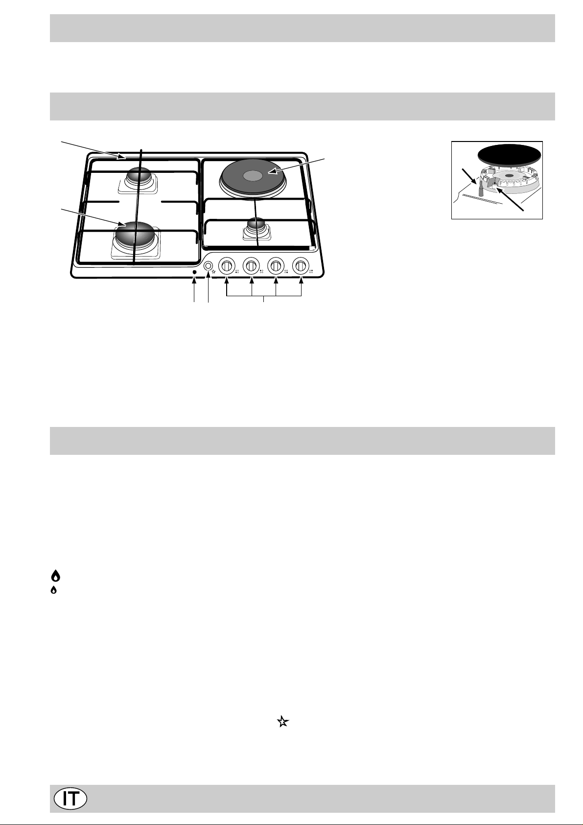
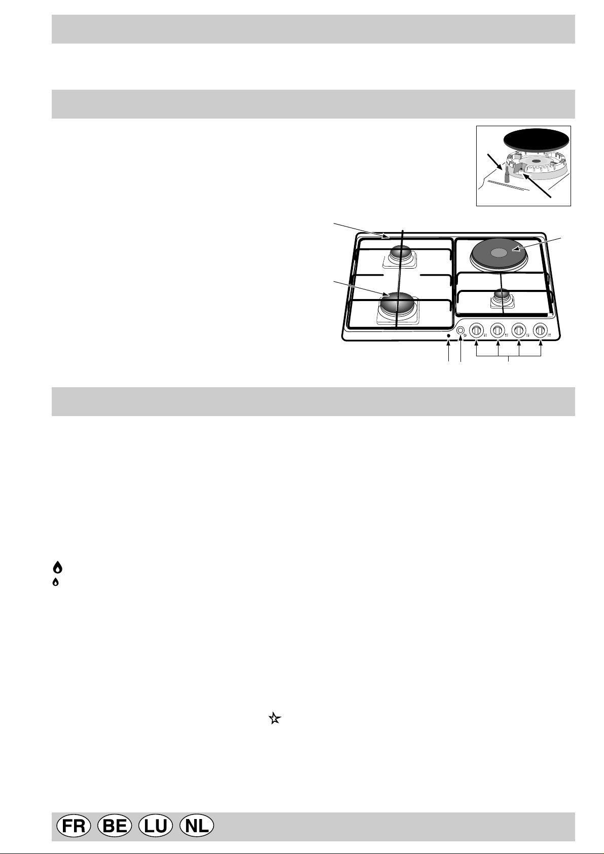
Visto da vicino
B
A
CHE
A. Bruciatori gas
B. Griglie di appoggio per recipienti di cottura
C. Manopole di comando dei bruciatori gas o della
piastra elettrica
D. Candela di accensione dei bruciatori gas (presen-
te solo su alcuni modelli)
E. Pulsante di accensione dei bruciatori gas (presen-
te solo su alcuni modelli)
G
F. Dispositiv o di sicurezza (presente solo su alcuni mo-
delli) - Interviene in caso di spegnimento accidentale
della fiamma (trabocco di liquidi, correnti d'aria, ...)
bloccando l'erogazione del gas al bruciatore.
G. Piastra elettrica (presente solo su alcuni modelli)
H. Spia di funzionamento piastra elettrica (presente
solo su alcuni modelli)
F
D
Come utilizzarlo
Su ciascuna manopola è indicata la posizione del bruciatore
gas corrispondente o della piastra elettrica (ove presente).
Bruciatori gas
Sono di diverse dimensioni e potenze. Scegliete quello più
adatto al diametro del recipiente da utilizzare.
Il bruciatore prescelto può essere regolato dalla manopola
corrispondente come segue:
• Spento
Massimo
Minimo
Per accendere uno dei bruciatori, avvicinare allo stesso
una fiamma o un accenditore, premere a fondo e ruotare la
manopola corrispondente in senso antiorario fino alla posizione di massima potenza.
Nei modelli dotati di dispositivo di sicurezza "F", è ne-
cessario mantenere premuta la manopola per circa 6 secondi finchè non si scalda il dispositivo che mantiene automaticamente accesa la fiamma .
Nei modelli dotati di candela di accensione "D", per accendere il bruciatore prescelto, prima premere il pul-
sante di accensione “E”, identificato dal simbolo ,
poi premere a fondo e ruotare la manopola corrispon-
dente in senso antiorario fino alla posizione di massima potenza.
Avvertenza: nel caso di una estinzione accidentale delle
fiamme del bruciatore, chiudere la manopola di comando e
ritentare l’accensione dopo almeno 1 minuto.
Per spegnere il bruciatore occorre ruotare la manopola in
senso orario fino all’arresto (corrispondente al simbolo “•”).
Piastra elettrica (presenti solo su alcuni modelli)
Possono essere: "normali" o "rapide", quest' ultime si riconoscono dalle altre per la presenza di un bollo rosso al centro.
La regolazione può essere effettuata ruotando la manopola
corrispondente in senso orario o anti-orario su 6 posizioni
diverse:
0 Spento
1 Potenza minima
2÷5 Potenz e intermedie
6 Potenza massima
Nel capitolo "Consigli pratici per l'uso" sono riportate le corrispondenze fra le posizioni indicate sulle manopole e l'uso
per il quale le piastre sono consigliate.
Per qualsiasi posizione della manopola div ersa da quella di
spento, si ha l'accensione della spia di funzionamento "H".
2
Page 2
Come tenerlo in forma
Prima di ogni operazione disconnettere l'apparecchio dall'
alimentazione elettrica.
Per una lunga durata del piano è indispensabile eseguire frequentemente una accurata pulizia generale,
tenendo presente che:
• le parti smaltate ed il coperchio in vetro, se presenti,
vanno lavati con acqua tiepida senza usare polveri
abrasive e sostanze corrosiv e che potrebbero rovinarli;
• gli elementi mobili dei bruciatori vanno lavati frequentemente con acqua calda e detersivo avendo cura di
eliminare le eventuali incrostazioni;
• nei piani dotati di accensione automatica occorre procedere frequentemente ad una accurata pulizia della
parte ter minale dei dispositivi di accensione istantanea elettronica e verificare che i fori di uscita del gas
non siano ostruiti;
Consigli d'uso
Consigli pratici per l’uso dei bruciatori
Al fine di ottenere il massimo rendimento è utile ricordare
quanto segue:
• utilizzare recipienti adeguati a ciascun bruciatore (vedere tabella) al fine di evitare che le fiamme fuoriescano
dal fondo dei recipienti.
• utilizzare sempre recipienti a fondo piatto e con coperchio.
• al momento dell’ebollizione ruotare la manopola fino
alla posizione di minimo.
• le piastre elettriche si puliscono con uno strofinaccio
umido e si ungono con un pò d’olio quando sono ancora tiepide;
• l’acciaio inox può rimanere macchiato se a contatto
per lungo tempo con acqua fortemente calcarea o con
detergenti aggressivi (contenenti fosforo). Si consiglia
di sciacquare abbondantemente ed asciugare dopo la
pulizia. E’ inoltre opportuno asciugare eventuali trabocchi d’acqua.
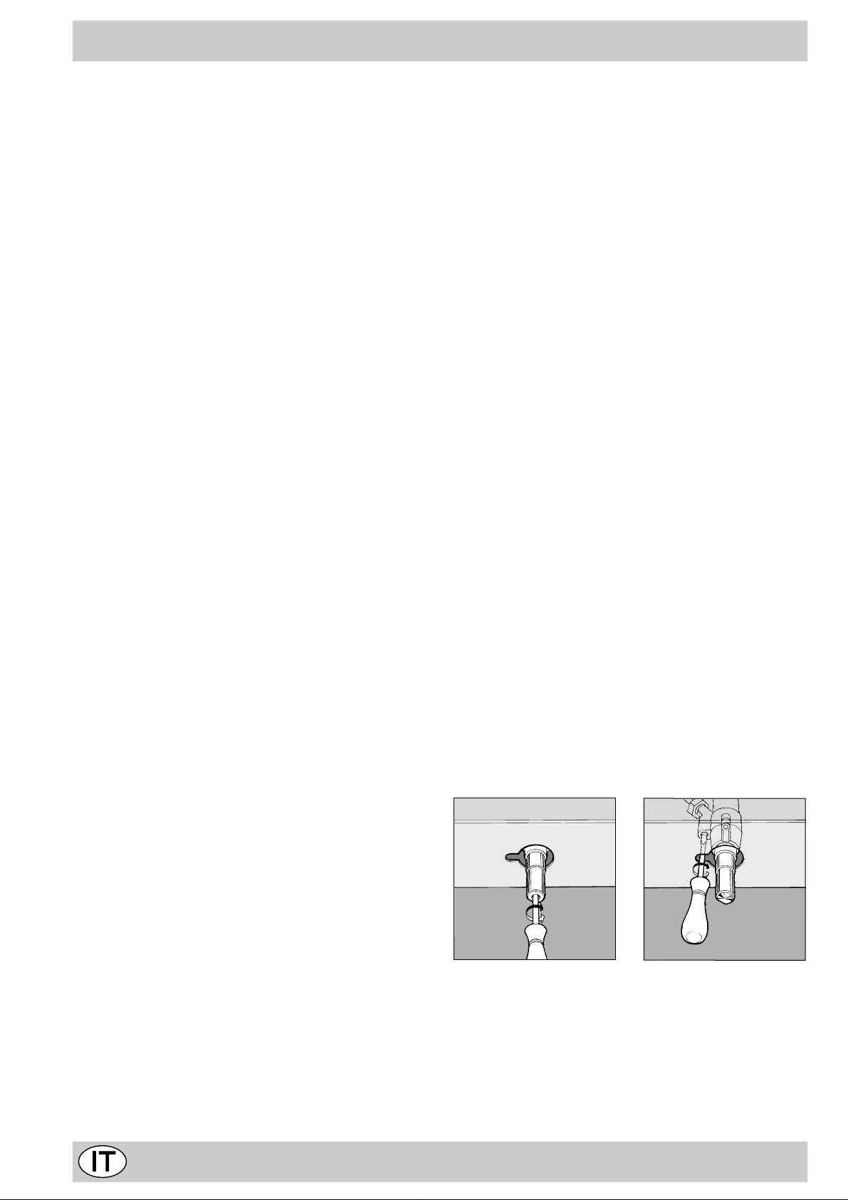
Ingrassaggio dei rubinetti
Con il tempo può verificarsi il caso di un rubinetto che si
blocchi o presenti difficoltà nella rotazione, pertanto sarà
necessario provvedere alla pulizia interna e alla sostituzione del grasso.
N.B.: Questa operazione deve essere effettuata da un
tecnico autorizzato dal costruttore.
Consigli pratici per l'uso delle piastre elettriche
Per e vitare dispersioni di calore e danni alla piastra è bene
usare recipienti con fondo piano e di diametro non inferiore a quello della piastra.
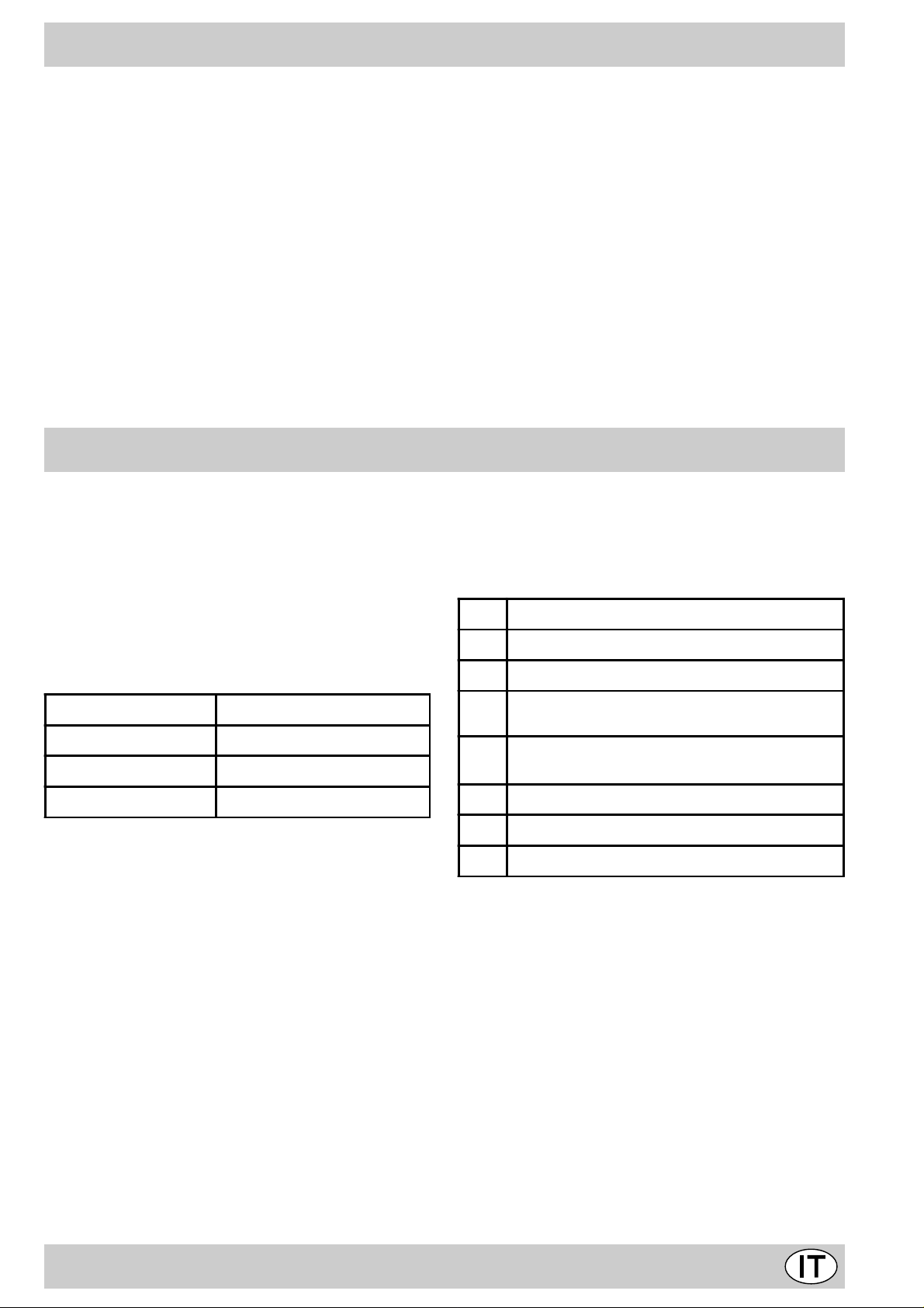
Pos. Piastra normale o rapida
Spento
0
Cottura di verdure, pesci
1
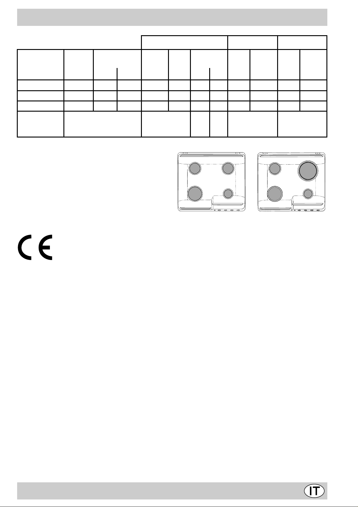
Bruciatore ø Diametro recipienti (cm)
Rapido (R) 24 – 26
Semi Rapido (S) 16 – 20
Ausiliario (A) 10 – 14
Cottura di patate (a vapore) minestre, ceci,
2
fagioli
Proseguimento di cottura di grandi quantità di
3
cibi, minestroni
4 Arrostire (medio)
Arrostire (forte)
5
Rosolare o raggiungere bollitura in poco tempo
6
3
Page 3

C'è qualche problema?
Può accadere che il piano non funzioni o non funzioni
bene. Prima di chiamare l'assistenza, vediamo che cosa
si può fare.
Innanzi tutto verificare che non ci siano interruzioni nelle
reti di alimentazione gas ed elettrica, ed in particolare i
rubinetti gas a monte del piano siano aperti.
Il bruciatore non si accende o la fiamma non è
uniforme.
Av ete controllato se:
• Sono ostruiti i fori di uscita del gas del bruciatore.
• Sono montate correttamente tutte le parti mobili che
compongono il bruciatore.
• Ci sono correnti d'aria nelle vicinanze del piano.
La fiamma non rimane accesa nelle versioni con
sicurezza.
Av ete controllato se:
• Non avete premuto a f ondo la manopola.
• Non avete mantenuto premuta a fondo la manopola
per un tempo sufficiente ad attivare il dispositivo di
sicurezza.
• Sono ostruiti i fori di fuoriuscita del gas in corrispondenza del dispositivo di sicurezza.
Il bruciatore in posizione di minimo non rimane
acceso.
Avete controllato se:
• Sono ostruiti i fori di fuoriuscita del gas.
• Ci sono correnti d'aria nelle vicinanze del piano.
• La regolazione del minimo non è corretta (Vedi paragrafo "Regolazione minimi").
I recipienti sono instabili.
Avete controllato se:
• Il fondo del recipiente è perfettamente piano.
• Il recipiente è centrato sul bruciatore o sulla piastra
elettrica.
• Le griglie sono state invertite.
Se, nonostante tutti i controlli, il piano non funziona e l'inconveniente da voi rilevato persiste, chiamate il Centro
Assistenza Tecnica Merloni Elettrodomestici più vicino, comunicando queste informazioni:
- Il tipo di guasto.
- La sigla del modello (Mod. ...) riportata sul certificato di
garanzia.
Non ricorrete mai a tecnici non autorizzati e rifiutate sempre l'installazione di pezzi di ricambio non originali.
4
Page 4

La sicurezza una buona abitudine
Per garantire l’efficienza e la sicurezza di questo elettrodomestico:
• rivolgetevi esclusiv amente a centri di assistenza tecnica autorizzati
• richiedete sempre l’utilizzo di parti di ricambio originali
• Questo libretto riguarda un piano di cottura da incasso
di classe3.
• L'apparecchio è concepito per uso non professionale
nelle abitazioni e le sue caratteristiche non vanno modificate.
• Le istruzioni sono valide solo per i paesi di destinazione i cui simboli figurano sul libretto e sulla targa matricola.
• La sicurezza elettrica di questo apparecchio è assicurata soltanto quando lo stesso è correttamente collegato ad un efficiente impianto di messa a terra come
previsto dalle vigenti norme di sicurezza.
T rattandosi di fonti di pericolo, evitare c he bambini e
incapaci abbiano contatti con:
- i comandi e l'apparecchio in genere;
- gli imballaggi (sacchetti, polistirolo, chiodi ecc.);
- l'apparecchio, durante e subito dopo il funzionamento ,
visto il surriscaldamento;
- l'apparecchio inutilizzato (in questo caso vanno rese
innocue le parti che potrebbero essere pericolose).
V anno evitate le seguenti operazioni:
- toccare l'apparecchio con parti del corpo umide;
- l'uso quando si è a piedi nudi;
- tirare l'apparecchio o il cavo di alimentazione per staccarli dalla presa di corrente;
- operazioni improprie e pericolose;
- ostruire le aper ture di ventilazione o smaltimento calore;
- che il cavo di alimentazione di piccoli elettrodomestici
finisca su parti calde dell'apparecchio;
- l'esposizione ad agenti atmosferici (pioggia, sole);
- l'utilizzo di liquidi infiammabili nei pressi;
- l'impiego di adattatori, prese multiple e/o prolunghe;
- l'impiego di pentole instabili o deformate;
- lasciare accese le piastre elettriche senza pentole;
- chiudere il coperchio in vetro (se presente) con i bruciatori gas o le piastre elettriche ancore caldi;
- tentativi di installazione o riparazione senza l'intervento di personale qualificato.
Occorre assolutamente rivolgersi a personale
qualificato nei seguenti casi:
- installazione (secondo le istruzioni del costruttore);
- quando si hanno dubbi sul funzionamento;
- sostituzione della presa in caso di incompatibilità con
la spina dell'apparecchio.
Occorre rivolgersi a centri di assistenza autorizzati
dal costruttore nei seguenti casi:
- in caso di dubbio sull'integrità dell'apparecchio dopo
aver tolto l'imballaggio;
- danneggiamento o sostituzione del cavo di alimentazione;
- in caso di guasto o cattivo funzionamento, richiedendo i ricambi originali.
È opportuno effettuare le seguenti operazioni:
- solo la cottura dei cibi evitando altre operazioni;
- verificare l'integrità dopo aver tolto l'imballaggio;
- disconnettere l'apparecchio dalla rete di alimentazione elettrica in caso di cattivo funzionamento e prima di
qualsiasi operazione di pulizia o manutenzione;
- quando inutilizzato, disinserire l'apparecchio dalla rete
elettrica e chiudere il rubinetto del gas (se previsto);
- controllare sempre che le manopole siano nella posizione “•”/”o” quando l'apparecchio non è utilizzato;
- tagliare il cavo di alimentazione dopo averlo
disconnesso dalla rete elettrica quando si decide di
non utilizzare più l'apparecchio.
• Il costruttore non può essere considerato responsabile per eventuali danni derivanti da: errata installazione, usi impropri, erronei ed irragionev oli.
5
Page 5
Installazione dei piani da incasso
Le istruzioni che seguono sono rivolte all’installatore qualificato affinchè compia le operazioni di installazione
regolazione e manutenzione tecnica nel modo più corretto e secondo le norme in vigore.
Importante: qualsiasi intervento di regolazione, manutenzione etc. deve essere eseguito con il piano elettricamente disinserito.
Posizionamento
Importante: questo apparecchio può essere installato e
funzionare solo in locali permanentemente ventilati secondo le prescrizioni delle Norme UNI-CIG 7129 e 7131
in vigore. Debbono essere osservati i seguenti requisiti:
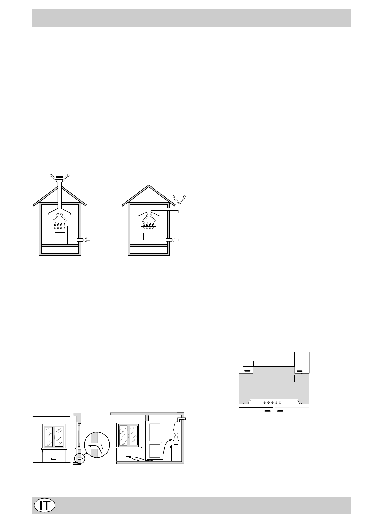
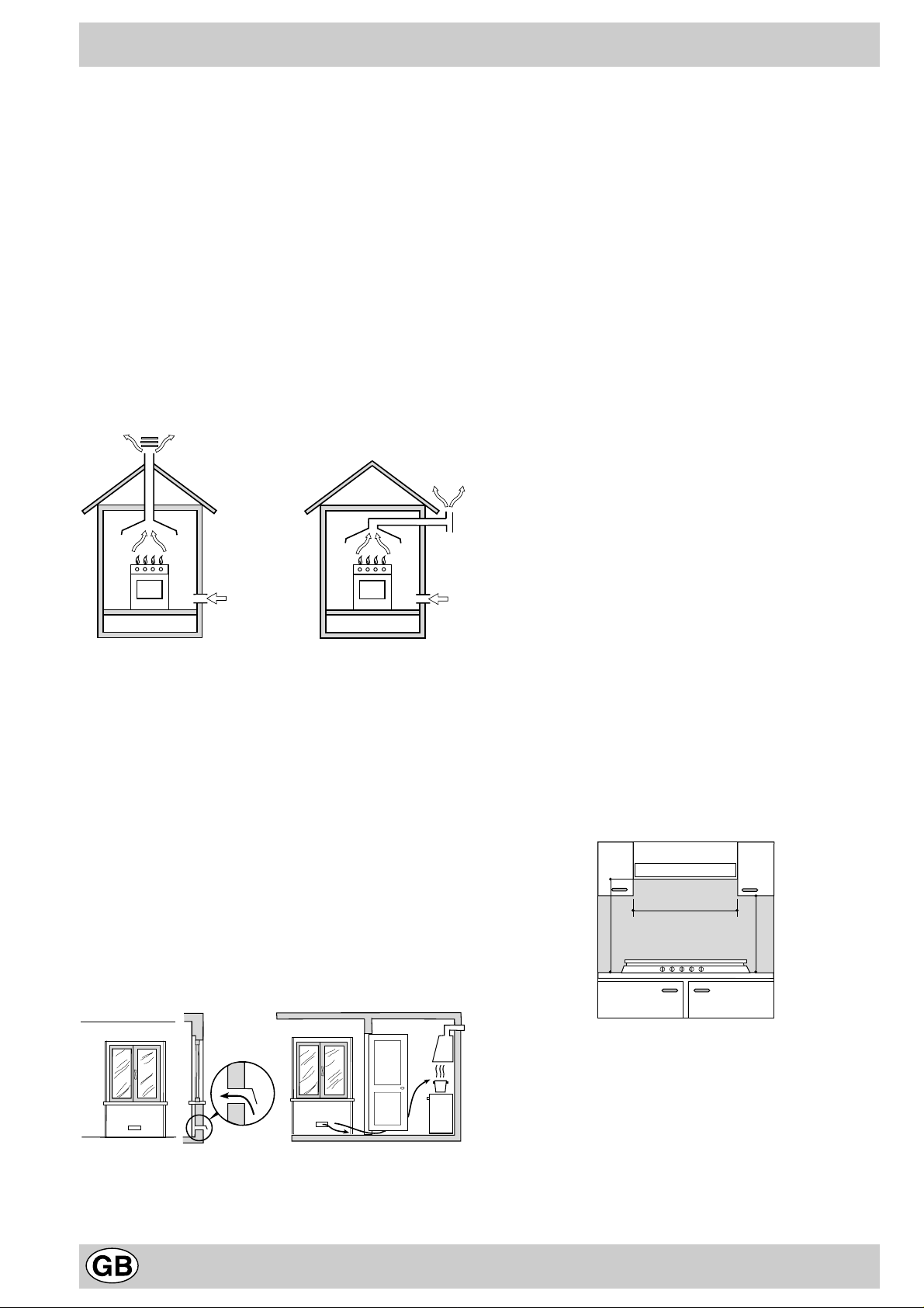
a) Il locale deve prevedere un sistema di scarico all’ester-
no dei fumi della combustione, realizzato tramite una
cappa o tramite un elettroventilatore che entri automaticamente in funzione ogni volta che si accende l’apparecchio.
In camino o in canna fumaria ramificata Direttamente all’esterno
(riservata agli apparecchi di cottura)
b) Il locale dev e pre vedere un sistema che consenta l’af-
flusso dell’aria necessaria alla regolare combustione.
La portata di aria necessaria alla combustione non deve
essere inferiore a 2 m³/h per kW di potenza installata.
Il sistema può essere realizzato prelevando direttamente l’aria dall’esterno dell’edificio tramite un condotto di
almeno 100 cm² di sezione utile e tale che non possa
essere accidentalmente ostruito. Per gli apparecchi privi sul piano di lavoro, del dispositivo di sicurezza per
assenza di fiamma, le aperture di ventilazione debbono essere maggiorate nella misura del 100%, con un
minimo di 200 cm² (Fig. A). Ovvero , in maniera indiretta da locali adiacenti, dotati di un condotto di ventilazione con l’esterno come sopra descritto, e che non
siano parti comuni dell’immobile, o ambienti con pericolo di incendio, o camere da letto (Fig. B).
Particolare A Locale Locale da
adiacente ventilare
c) Un utilizzo intensivo e prolungato dell’apparecchio può
necessitare di una aerazione supplementare per esempio l’apertura di una finestra o una aerazione più efficace aumentando la potenza di spirazione meccanica
se essa esiste.
d) I gas di petrolio liquefatti, più pesanti dell’aria, rista-
gnano verso il basso. Quindi i locali contenenti bidoni
di GPL debbono prevedere delle aperture verso l’esterno così da permettere l’evacuazione dal basso delle
eventuali fughe di gas . Pertanto i bidoni di GPL, siano
essi vuoti o parzialmente pieni, non debbono essere
installati o depositati in locali o vani a livello più basso
del suolo (cantinati, ecc.). É opportuno tenere nel locale solo il bidone in utilizzo, collocato in modo da non
essere soggetto all’azione diretta di sorgenti di calore
(forni, camini, stufe, ecc.) capaci di portarlo a temperature superiori ai 50°C.
Installazione dei piani da incasso
I piani a gas e misti sono predisposti con grado di protezione contro i riscaldamenti eccessivi di tipo X, è pertanto
possibile l’installazione a fianco di mobili la cui altezza
non superi quella del piano di lavoro. Per una corretta installazione del piano di cottura vanno osservate le seguenti precauzioni:
a) I mobili situati a fianco, la cui altezza superi quella del
piano di lavoro , debbono essere situati ad almeno 110
mm. dal bordo del piano stesso.
b) Le cappe debbono essere installate secondo i requisi-
ti richiesti nei libretti istruzioni delle cappe stesse, comunque ad una distanza minima di 650 mm.
c) Nel caso di cappe larghe 600 mm., oltre a rispettare
quanto specificato al punto b), è necessario posizionare i pensili adiacenti alla cappa ad un’altezza minima dal top di 540 mm., tale da consentire l’eventuale
installazione del coperchio e la sua corretta
manovrabilità, e in ogni caso ad una distanza dal top
tale da permettere un’agevole uso delle pentole sull’apparecchio.
d) Allorchè il piano di cottura venga installato sotto un
pensile, quest’ultimo dovrà mantenere una distanza
minima dal top pari a 700 mm (millimetri).
600mm min.
700mm min.
540mm min.
A
Esempi di aperture di ventilazione Maggiorazione della fessura fr a
per l’aria comburente porta e pavimento
Fig. A Fig. B
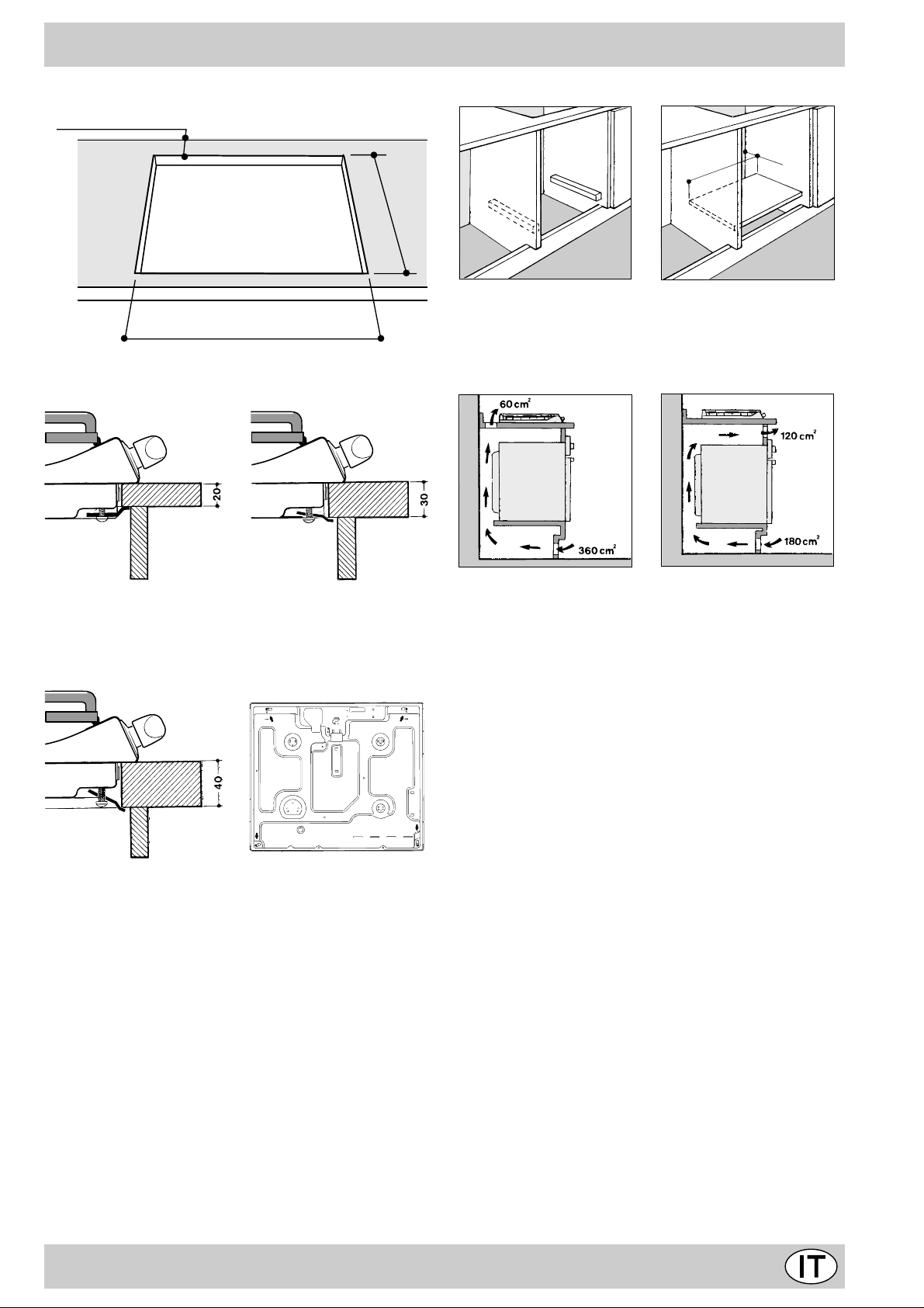
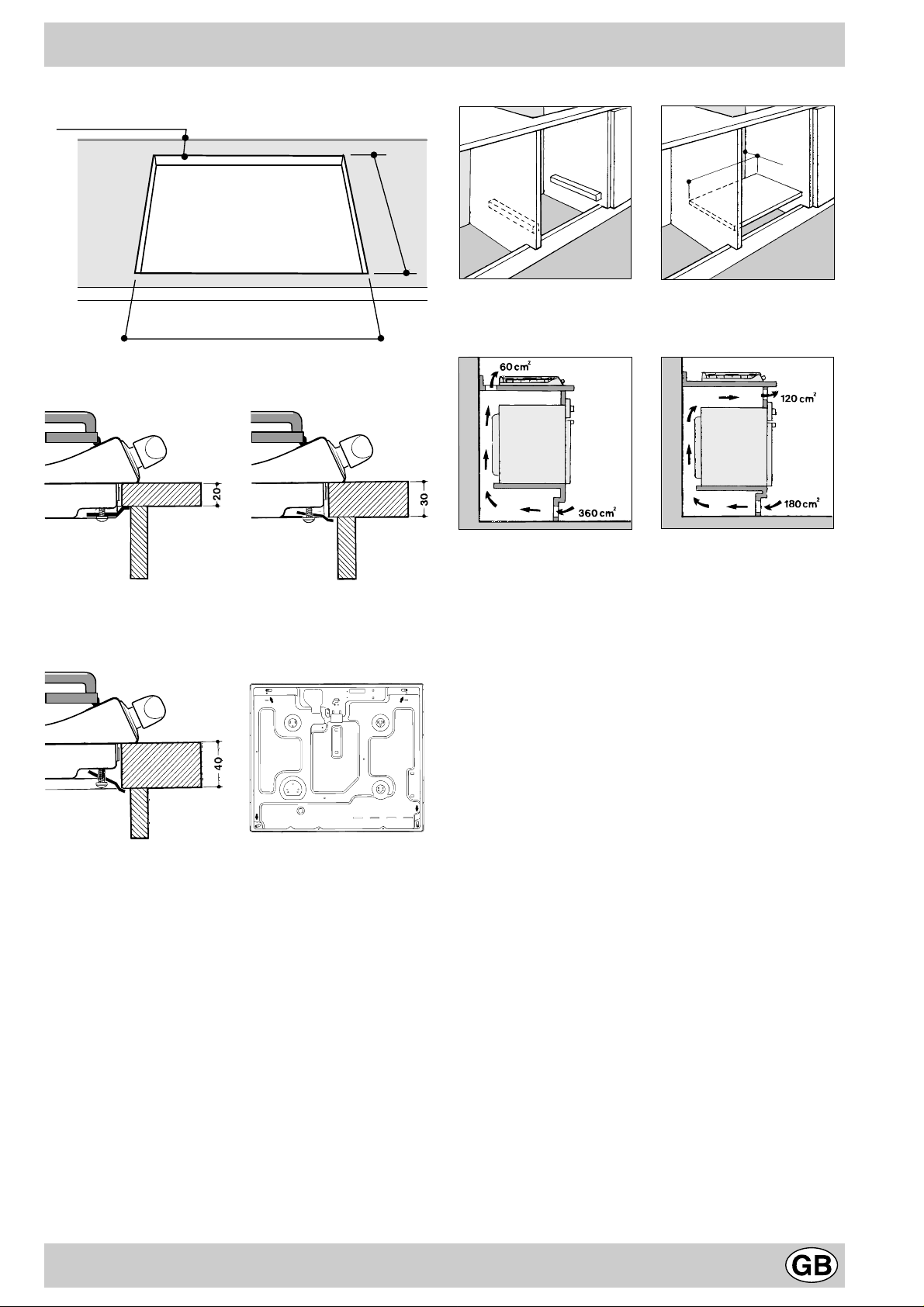
e) Il vano del mobile dovrà avere le dimensioni indicate
nella figura. Sono previsti dei ganci di fissaggio che
consentono di fissare il piano su top da 20 a 40 mm. di
spessore. Per un buon fissaggio del piano è
consigliabile usare tutti i ganci a disposizione.
6
Page 6
55
mm
555
Schema di fissaggio dei ganci
mm
45 mm.
560 mm.
475
mm
Nel caso di installazione sopra un forno da incasso senza
ventilazione forzata di raffreddamento, per consentire
un’adeguata areazione all’interno del mobile vanno garantite delle prese d’aria di ingresso e di uscita. Possibili
esempi di montaggio sono illustrati nelle figure sottostanti.
Posizione gancio per Posizione gancio per
top H=20mm top H=30mm
Avanti
Posizione gancio per Dietro
top H=40mm
N.B: Usare i ganci contenuti nella "confezione accessori"
f) Nel caso in cui il piano non sia installato su di un forno
incasso, è necessario inserire un pannello di legno
come isolamento. Esso dovrà essere posizionato ad
una distanza minima di 20 mm. dalla parte inferiore
del piano stesso.
Nota: Nel caso in cui il piano sia installato su di un forno
incasso, è preferibile installare il forno in modo che appoggi su due listelli in legno; nel caso in cui sia presente
un piano continuo di appoggio questo dev e avere un’apertura posteriore di almeno 45 x 560 mm.
Collegamento gas
Il collegamento dell’apparecchio alla tubazione o alla bombola del gas dovrà essere effettuato come prescritto dalle
Norme UNI-CIG 7129 e 7131, solo dopo essersi accertati
che esso è regolato per il tipo di gas con cui sarà alimentato.
In caso contrario eseguire le operazioni indicate al paragrafo “Adattamento ai div ersi tipi di gas”. Nel caso di alimentazione con gas liquido, da bombola, utilizzare regolatori di
pressione conformi alle Norme UNI-CIG 7432.
Importante: per un sicuro funzionamento, per un adeguato
uso dell’energia e maggiore durata dell’apparecchiatura, assicurarsi che la pressione di alimentazione rispetti i valori
indicati nella tabella 1 “Caratteristiche dei bruciatori ed ugelli”.
Allaccio con tubo rigido (rame o acciaio)
L’allaccio all’impianto gas deve essere eff ettuato in modo da
non provocare sollecitazioni di alcun genere all’apparecchio .
Sulla rampa di alimentazione dell’apparecchio è presente
un raccordo a “L” orientabile, la cui tenuta è assicurata da
una guarnizione. Nel caso risulti necessario ruotare il raccordo sostituire tassativamente la guarnizione di tenuta (in
dotazione con l’apparecchio). Il raccordo di entr ata del gas
all’apparecchio è filettato 1/2 gas maschio cilindrico.
Allaccio con tubo flessibile in acciaio inossidabile a
parete continua con attacchi filettati
Il raccordo di entrata del gas all’apparecchio è filettato
1/2 gas maschio cilindrico. Utilizzare esclusivamente tubi
conformi alla Norma UNI-CIG 9891 e guarnizioni di tenuta conformi alla UNI-CIG 9264. La messa in opera di tali
tubi deve essere effettuata in modo che la loro lunghezza, in condizioni di massima estensione, non sia maggiore di 2000 mm. Ad allacciamento avvenuto assicur arsi che
il tubo metallico flessibile non venga a contatto con parti
mobili o schiacciato.
7
Page 7
Controllo tenuta
Ad installazione ultimata controllare la perfetta tenuta di
tutti i raccordi utilizzando una soluzione saponosa e mai
una fiamma.
Collegamento elettrico
I piani dotati di cavo di alimentazione tripolare, sono predisposti per il funzionamento con corrente alternata alla
tensione e frequenza di alimentazione indicate sulla
targhetta caratteristiche (posta sulla parte inferiore del
piano). Il conduttore di terr a del cavo è contraddistinto dai
colori giallo-verde. Nel caso di installazione sopra un forno da incasso l’allaccio elettrico del piano e quello del
forno deve essere realizzato separatamente, sia per ragioni di sicurezza elettrica che per facilitare l’eventuale
estraibilità del forno.
Allacciamento del cavo di alimentazione alla rete
Montare sul cavo una spina normalizzata per il carico indicato sulla targhetta caratteristiche, nel caso di collegamento diretto alla rete è necessario interporre tra l’apparecchio e la rete un interruttore omnipolare con apertura
minima fra i contatti di 3 mm. dimensionato al carico e
rispondente alle norme in vigore (il filo di terra non deve
essere interrotto dall’interruttore). Il cavo di alimentazione deve essere posizionato in modo che non raggiunga
in nessun punto una temperatura superiore di 50°C a
quella ambiente.
Prima di effettuare l’allacciamento accertarsi che:
• la valvola limitatrice e l’impianto domestico possano
sopportare il carico dell’apparecchiatura (vedi targhetta
caratteristiche);
• l’impianto di alimentazione sia munito di efficace collegamento a terra secondo le norme e le disposizioni
di legge;
• la presa o l’interruttore omnipolare siano facilmente
raggiungibili con il piano installato.
N.B: non utilizzare riduzioni, adattatori o derivatori in quanto essi potrebbero provocare riscaldamenti o bruciature.
Adattamento ai diversi tipi di gas
Per adattare il piano ad un tipo di gas diverso da quello
per il quale esso è predisposto (indicato sulla etichetta
fissata nella parte inferiore del piano o sull'imballo), occorre sostituire gli ugelli dei bruciatori effettuando le seguenti operazioni:
• togliere le griglie del piano e sfilare i bruciatori dalle
loro sedi.
• svitare gli ugelli, servendosi di una chiave a tubo da
7mm. e sostituirli con quelli adatti al nuov o tipo di gas
(vedi tabella 1 “Caratteristiche dei bruciatori ed ugelli”).
• rimontare le parti eseguendo all’inverso le operazioni.
• al termine dell’operazione, sostituite la vecchia etichetta
taratura con quella corrispondente al nuovo gas d’utilizzo, reperibile presso i Nostri Centri Assistenza Tecnica.
Qualora la pressione del gas utilizzato sia diversa (o variabile) da quella prevista, è necessario installare, sulla
tubazione di ingresso, un appropriato regolatore di pressione, secondo UNI-CIG 7430 (regolatori per gas
canalizzati).
Regolazione aria primaria dei bruciatori
I bruciatori non necessitano di nessuna regolazione dell’aria primaria.
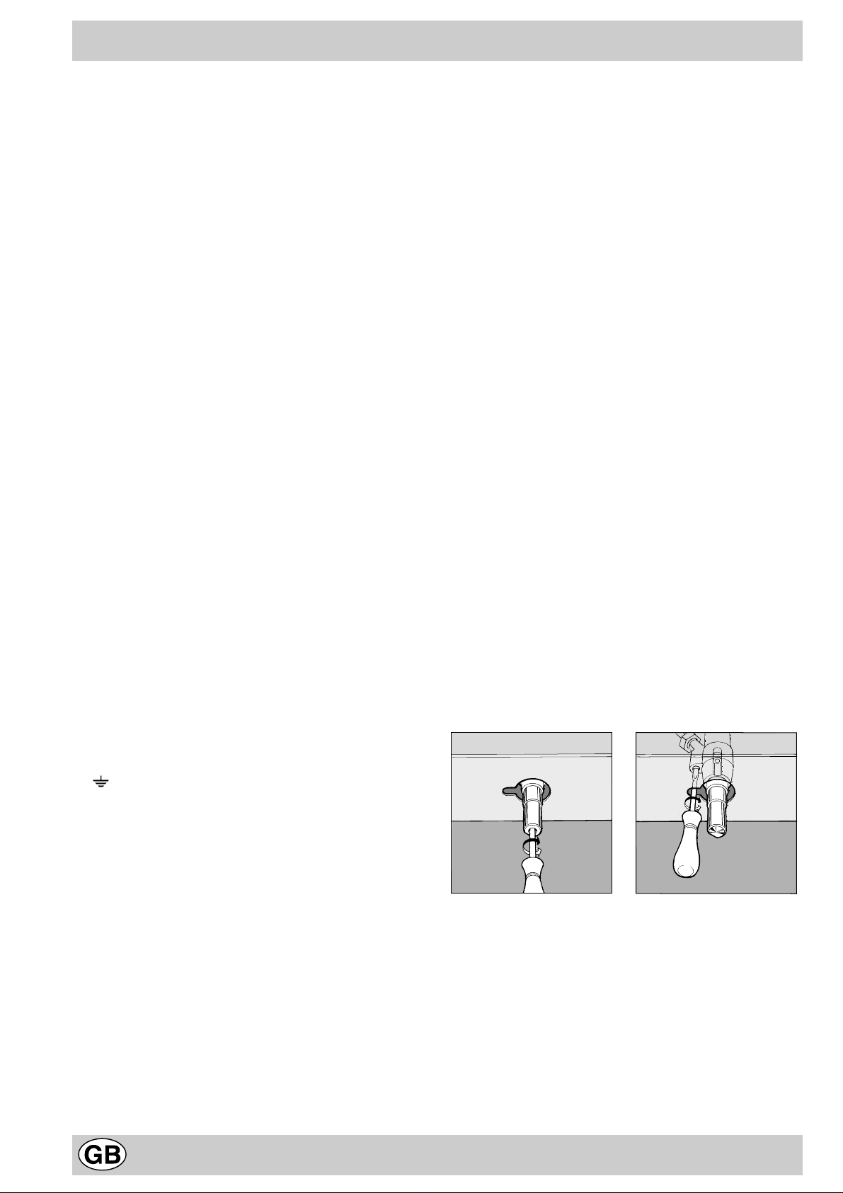
Regolazione minimi
• Portare il rubinetto sulla posizione di minimo;
• T ogliere la manopola ed agire sulla vite di regolazione
posta all’interno o di fianco all’astina del rubinetto fino
ad ottenere una piccola fiamma regolare.
N.B.: nel caso dei gas liquidi, la vite di regolazione dovrà
essere avvitata a fondo .
• V erificare che ruotando rapidamente la manopola dalla posizione di massimo a quella di minimo non si abbiano spegnimenti dei bruciatori.
• Negli apparecchi provvisti del dispositivo di sicurezza
(termocoppia), in caso di mancato funzionamento del
dispositivo con bruciatori al minimo aumentare la portata dei minimi stessi agendo sulla vite di regolazione.
Effettuata la regolazione, ripristinate i sigilli posti sui bypass con ceralàcca o materiali equivalenti.
8
Page 8
Caratteristiche dei bruciatori ed ugelli
Tabella 1 Gas liquido Gas naturale Gas citt à
Bruciatore Diametr o
(mm)
Potenza termica
kW (p.c.s.*)
By-Pass
1/100
ugello
1/100
portata*
g/h
ugello
1/100
portata*
l/h
ugello
1/100
portata*
l/h
Nomin. Rid o t. (mm) (mm) *** ** (mm) (mm)
Rapido (R)
100 3,00 0,70 41 86 218 214 116 286 285 680
Semi Rapido (S) 75 1,90 0,40 30 70 138 136 106 181 200 431
Ausiliario (A) 55 1,00 0,40 30 50 73 71 79 95 145 227
Pressioni
di
alimentazione
Nominale (mbar)
Minima (mbar)
Massima (mbar)
28-30
20
35
37
25
45
20
17
25
8
6
15
* A 15°C e 1013 mbar-gas secco
** Propano P.C.S. = 50,37 MJ/Kg
*** Butano P.C.S. = 49,47 MJ/Kg
Naturale P.C.S. = 37,78 MJ/m
Città P.C.S. = 15,87 MJ/m
Attenzione: Conformemente alla Direttiva CEE 90/396
3
3
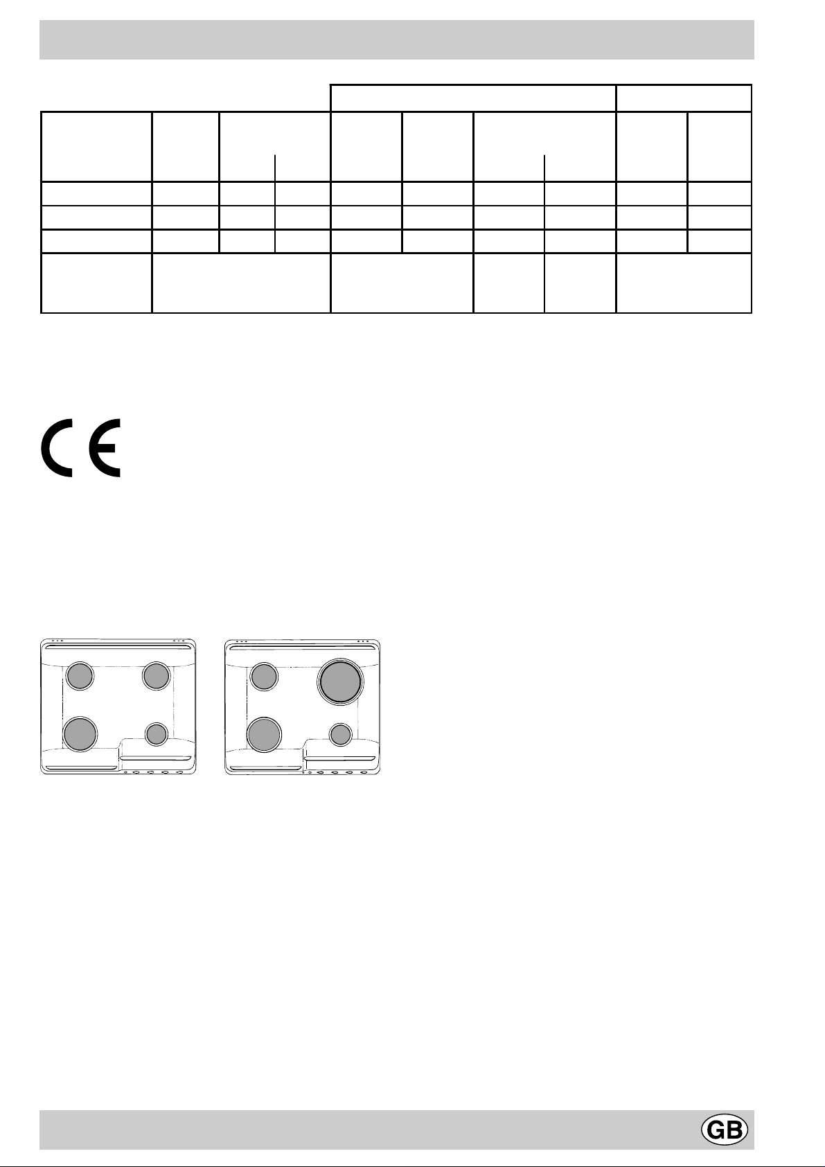
SS
AR
S
AR
l’adattabilità al Gas Città è consentita solo per apparecchi con dispositivo di sicurezza contro le fughe di gas (riferimento F). P er la trasf ormazione a gas città, richiedere
il kit ugelli presso un centro di assistenza Tecnica Merloni
Elettrodomestici.
PF 640.1 PF 631.1
PF 640 A PF 631 A
PF 640 AS PF 631 AS
Questa apparecchiatura è conforme alle seguenti
Direttive Comunitarie:
- 73/23/CEE del 19/02/73 (Bassa Tensione) e successive modificazioni;
- 89/336/CEE del 03/05/89 (Compatibilità Elettromagnetica) e successive modificazioni;
- 90/396/CEE del 29/06/90 (Gas) e successive
modificazioni;
- 93/68/CEE del 22/07/93 e successive modificazioni.
9
Page 9
Congratualtions on choosing an Ariston appliance, which you will find is dependable and easy to use . W e recommend
that you read this manual for best performance and to extend the life of your appliance . Thank you.
Close-up View
B
A
CHE
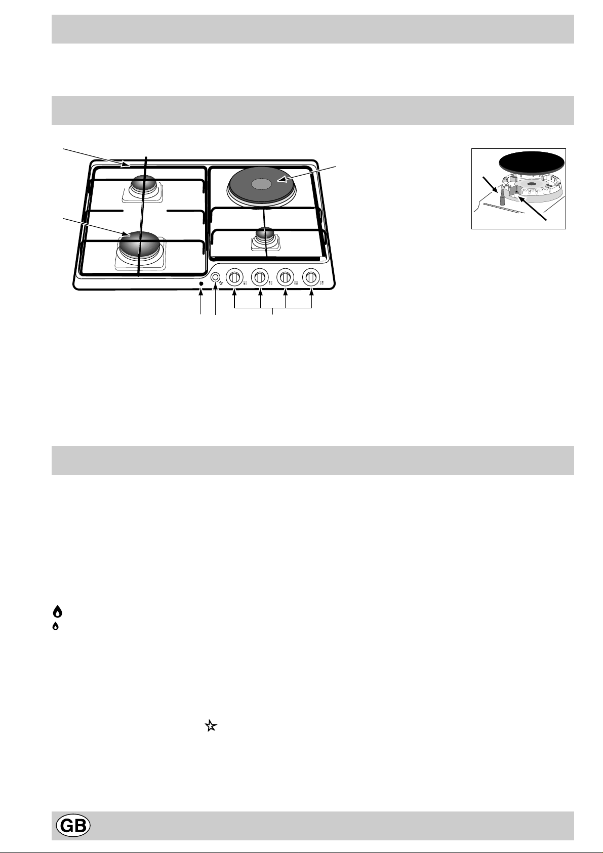
A. Gas Burners
B. Support Grid for Cookware
C. Control Knobs for Gas Burners and Electric Hot
Plate
D. Ignitor for Gas Burners (only on certain models)
E. Ignition Button for Gas Burners (only on certain
models)
G
F. Safety Device (only on certain models) - Activates if
the flame accidentally goes out (spills, drafts, etc.),
interrupting the delivery of gas to the burner.
G. Electric Hot Plate (only on certain models)
H. Indicator Light for Electric Hot Plate (only on certain
models)
F
D
How T o Use Y our Appliance
The position of the corresponding gas burner or electric
hot plate (if present) is indicated on each control knob.
Gas Burners
The burners differ in size and power. Choose the most
appropriate one for the diameter of the cookware being
used.
The burner can be regulated with the corresonding control
knob by using one of the following settings:
• Off
High
Low
T o turn on one of the b urners, place a lighted match or
lighter near the burner, press the knob all the way in and
turn in the counter-clockwise direction to the "High" setting.
On those models fitted with a safety device (F), the
knob must be pressed in for about 6 seconds until the
device that keeps the flame lighted w arms up .
On those models fitted with an ignitor (D), the "E"
ignition button, identified b y the symbol, must first
be pressed and then the corresponding knob pushed
all the way in and turned in the counter-clockwise
direction to the "High" setting.
Caution: If the burner accidently goes out, turn off the
gas with the control knob and try to light it again after
waiting at least 1 minute.
To turn off a burner, turn the knob in the clockwise
direction until it stops (it should be on the “•” setting).
Electric Hot Plate (only on certain models)
The hot plate can be: "normal" and "fast". The latter can
be identified by a red boss in the center of the hot plate
itself.
The hot plate can be regulated by turning the
corresponding knob in the clockwise or counter-clockwise
direction to any one of the 6 different settings:
0 Off
1 Low
2-5 Medium
6 High
The section entitled, "Practical Cooking Advise", provides
information on the recommended settings for various types
of food or cooking processes.
When the knob is on any of the settings other than "Off",
the "H" operating light comes on.
10
Page 10
How to Keep Your Cooktop in Shape
Before cleaning or performing maintenance on your
appliance, disconnect it from the electrical power supply.
To extend the life of the cooktop, it is absolutely
indispensable that it be cleaned carefully and
thoroughly on a frequent basis, keeping in mind the
following:
• The enameled parts and the glass top, if present, must
be washed with warm water without using abrasive
powders or corrosive substances which could ruin
them;
• The removable parts of the burners should be washed
frequently with warm water and soap, making sure to
remove caked-on substances;
• On cooktops with automatic ignition, the end of the
electronic ignition device must be cleaned carefully and
frequently, making sure that the gas holes are not
clogged;
Practical Advice
Practical Advise on Using the Burners
For best performance, f ollo w these general guidelines:
• Use the appropriate cookware for each burner (see
table) in order to prevent the flame from reaching the
sides of the pot or pan;
• Alwasy use cookware with a flat bottom and keep the
lid on;
• When the contents come to a boil, turn the knob to
"Low".
• The electric hobs should be cleaned using a damp cloth
and then rubbed with oil while still warm;
• Stainless steel can be stained if it remains in contact
with highly calcareous water or aggressive detergents
(containing phosphorous) for an extended period of
time. It is recommended that these parts be rinsed
thoroughly with water and then dried well. It is also a
good idea to clean up any spills.
Greasing the Gas Valves
Over time, the gas v alves ma y stick or become difficult to
turn. If this is the case, the must be cleaned on the inside
and the regreased.
N.B.: This pr ocedure must be performed by a technician
authorized by the manufacturer .
Practical Advice on Using the Electric Hot Plates
In order to avoid heat loss and damage to the hot plate,
use cookware with a flat bottom the diameter of which is
not less than that of the hot plate.
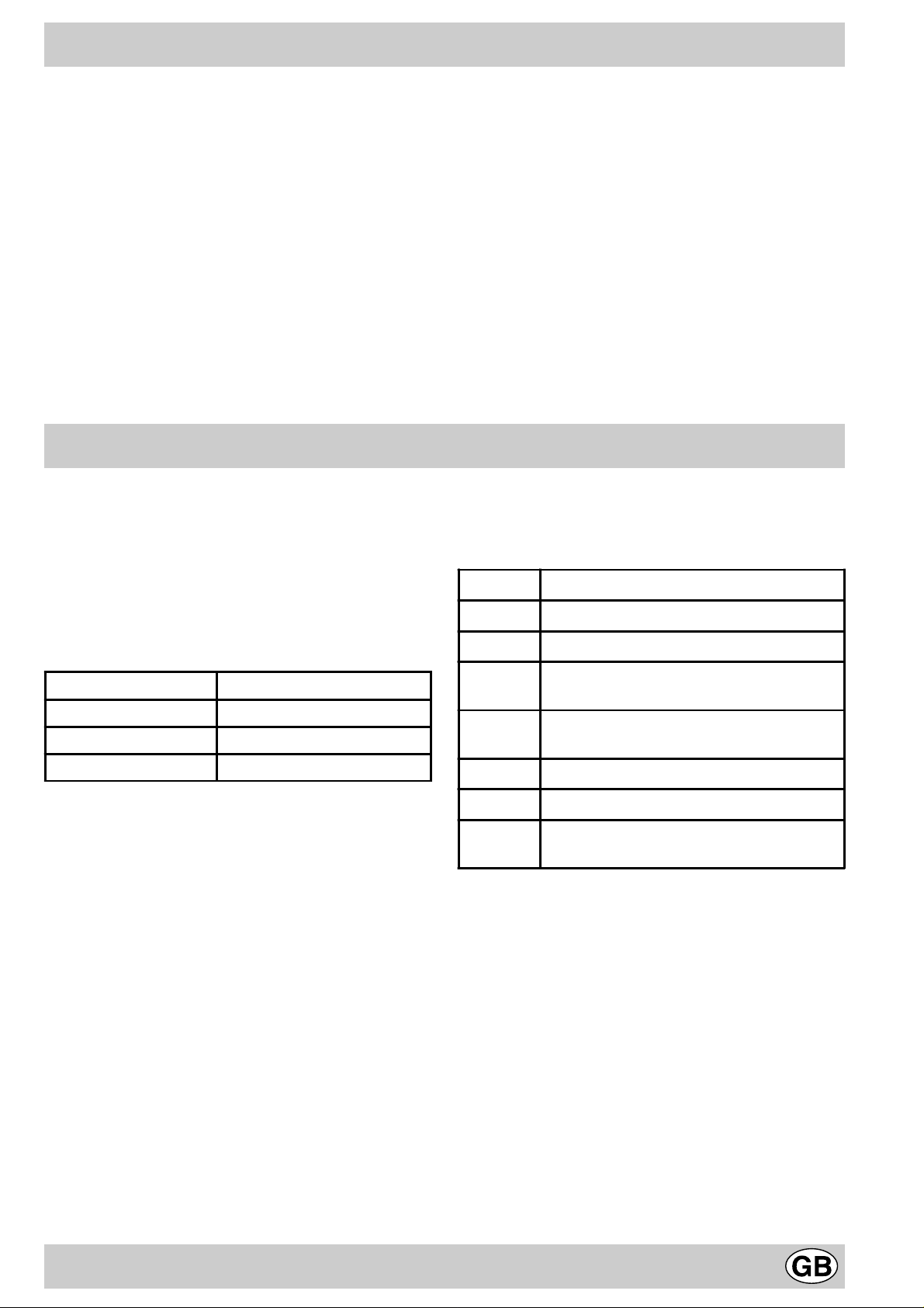
Setting Normal or Fast Plate
0
Off
Cooking vegetables, fish
1
Burner ø Cookware diameter (cm)
Fast (R) 24 - 26
Semi Fast (S) 16 - 20
Auxiliary (A) 10 - 14
2
3
4
5
6
Cooking potatoes (using steam) so ups,
chickpeas, beans.
Continuing the cooking of lar ge quanti ties of
food, minestrone
For roasting (average)
For roasting (above average)
For browning and reaching a boil in a short
time.
11
Page 11

Is there a problem?
It may occur that the cooktop does not function or does
not function properly . Before calling customer service for
assistance, lets see what can be done.
First of all, check to see that there are no interruptions in
the gas and electrical supplies, and, in particular, that the
gas valves for the mains are open.
The burner does not light or the flame is not uniform
around the burner .
Check to make sure that:
• The gas holes on the burner are not clogged;
• All of the movable parts that make up the burner are
mounted correctly;
• There are no draughts around the cooking surface.
The flame does not stay lighted on the model with the
safety device.
Check to make sure that:
• You press the knob all the way in;
• You keep the knob pressed in long enough to activate
the safety device .
• The gas holes are not clogged in the area
corresponding to the safety device .
The burner does not remain on when set to "Low".
Check to make sure that:
• The gas holes are not clogged.
• There are no draughts near the cooking surface.
• The minimum has been adjusted correctly (see the
section entitled, "Minimum Regulation").
The cookware is not stable.
Check to make sure that:
• The bottom of the cookware is perfectly flat.
• The cookware is centered correctly on the burner or
electric hot plate.
• The support grids have not been inverted.
If, despite all of these checks, the cooktop does not
function properly and problem persists, call the nearest
Merloni Elettrodomestici Customer Service Centre,
informing them of:
- The type of prob lem.
- The abbre viation used to identify the model (Mod. ...) as
indicated on the warranty.
Never call upon technicians not authorized by the
manufacturer, and refuse to accept spare parts that are
not original.
12
Page 12

Safety Is a Good Habit to Get Into
T o maintain the EFFICIENCY and SAFETY of this appliance, we recommend:
• call only the Service Centers authorized by the manufacturer
• always use original Spare Parts
• This manual is for a class 3 built-in cooktop.
• This appliance is designed for non-prof essional use in
the home and its features and technical characteristics
must not be modified.
• These instructions are only valid for the countries the
symbols for which appear on the manual and the serial
plate.
• The electrical system of this appliance is safe only when
it is correctly connected to an adequate earthing
system, as required by current safety standards.
Prevent children and the disabled from coming into
contact or having access to the following, as they are
possible sources of danger:
- The controls and the appliance in general;
- The packaging (plastic bags, polystyrene, nails, etc.);
- The appliance, during and immediately after use given
the heat generated by its use;
- The appliance when no longer in installed (in this case,
all potentially dangerous parts must be made safe).
The following should be av oided:
- Touching the appliance with wet parts of the body;
- Using the appliance with bare feet;
- Pulling on the appliance or the power supply cord to
disconnect them from the electrical outlet;
- Improper and/or dangerous use;
- Obstructing the ventilation or heat dissipation slots;
- Allowing the power supply cord of small appliances to
come into contact with the hot parts of the cooktop;
- Exposure to atmospheric agents (rain, sun);
- Using flammable liquids nearby;
- Using adaptors, multiple outlet plugs and/or extensions;
- Using unstable or deformed cookware;
- Leaving the electric hobs on without cookware on top
of them;
- Closing the glass top (if present) while the gas burners
or electrical hot plates are still hot;
- Tr ying to install or repair the appliance without the
assistance of qualified personnel.
The assistance of qualified personnel must be called
upon in the following cases:
- Installation (in accordance with the manufacturer's
instructions);
- When in doubt about the operation of the appliance;
- Replacement of the electrical outlet becuase it is
incompatible with the plug.
Contact service centers authorized by the
manufacturer in the following cases:
- When in doubt about the condition of the appliance
after having remov ed the packing;
- Damage to or replacement of the power supply cord;
- In the case of a breakdown or malfunction: ask for
original spare parts.
It is recommended that you follo w the guidelines
below:
- Only use the appliance to cook food, avoiding all other
uses;
- Check the condition of the appliance after it has been
unpacked;
- Disconnect the appliance from the power supply in the
event of malfunction and always before cleaning or
maintenance;
- When not in use, disconnect the appliance from the
power supply and turn off the gas valve (if present);
- Always check to make sure that the control knobs are
on the “•”/”o” setting when the appliance is not in use;
- Cut the power supply cord after disconnecting it from
the electrical mains when you decide to no longer use
the appliance.
• The manufacturer will not be held liable for any
damages arising out of : incorrect installation or
improper, incorrect or unreasonable use ..
13
Page 13
Installation Instructions for b uilt-in
The following instructions are intended for the installer so
that the installation and maintenance procedures may be
followed in the most prof essional and expert manner possible.
Important: Disconnect the appliance from the electrical
supply before performing an y maintenance or regulation
upkeep work.
Positioning the Cooktop
Important: this unit may be installed and used only in
permanently ventilated rooms in accordance with British
Standard Codes Of Practice: B.S. 6172 / B.S. 5440, Par. 2
and B.S. 6891 Current Editions. The f ollowing requirements
must be observed:
a) The room must be fitted with a ventilation system which
vents smoke and gases from comb ustion to the outside.
This must be done by means of a hood or electric
ventilator that turns on automatically each time the hood
is operated.
In a chimney stack or branched flue. Directly to the Outside
(exclusively for cooking appliances)
b) The room must also allow for the influx of the air needed
for proper combustion. The flow of air for combustion
purposes must not be less than 2 m³/h per kW of
installed capacity . The supply of said air can be eff ected
by means of direct influx from the outside through a
duct with a inner cross section of at least 100 cm² which
must not be able to be accidentally blocked. Those
appliances which are not fitted with a safety device to
prevent the flame from accidentally going out m ust have
a ventilation opening twice the size otherwise required,
i.e. a minimum of 200 cm² (Fig. A). Otherwise, the room
can be vented indirectly through adjacent rooms fitted
with ventilation ducts to the outside as described above,
as long as the adjacent rooms are not shared areas,
bedrooms or present the risk of fire (Fig. B).
Detail A Adjacent Room to be
Room V ented
c) Intensive and prolonged use of the appliance may ne-
cessitate supplemental ventilation, e.g. opening a
window or increasing the power of the air intak e system
(if present).
d) Liquidified petroleum gases are heavier than air and,
as a result, settle downwards. Rooms in which LPG
tanks are installed must be fitted with ventilation
openings to the outside in order to allow the gas to
escape in the event of a leak. Therefore, LPG tanks,
whether empty or partially full, must not be installed or
stored in rooms or spaces below ground lev el (cellars,
ect.). It is also a good idea to keep only the tank
currently being used in the room, making sure that it is
not near sources of heat (ovens, fireplaces, stoves,
etc.) that could raise the internal temperature of the
tank above 50°C .
Installation of Built-in Cooktops
The gas cooktops are equipped with type X degree protection
against overheating. Theref ore, the appliance can be installed
next to cabinets, provided the height of the cabinet does not
exceed that of the hob . F or proper installation of the cooktop,
the following guidlines must be f ollowed:
a) If the cabinet(s) located next to the cooktop are higher
than the cooktop itself, the cabinet(s) must be installed at
least 110 mm from the edge cooktop;
b) Hoods must be installed in accordance with the
instructions contained in the installation manual for the
hoods themselves, and no less than 650 mm from the
cooktop;
c) In the case of the 600 mm cooker hoods, besides following
the recommendations in point b), the cabinets should be
positioned next to the hood at a height of at least 540 mm
from the top since this will make it possible to install the
lid and move it correctly. The cabinet should always be
installed at a height from the top which allows easy use
of pots and pans on the cooker.
d) Should the cooktop be installed directly under a cupboard,
the latter should be at least 700 mm (millimetres) from
the top, as shown in Figure .
600mm min.
700mm min.
540mm min.
A
Examples of ventilation holes Enlarging the ventilation slot
for comburant air . between window and floor.
Fig. A Fig. B
e) The dimensions of the cutout for the appliance must be
those indicated in the figure. Clamps are provided to fasten
the cooktop to counters measuring from 20 to 40 mm in
thickness. To fasten the cooktop securely, it is
recommended that all the clamps be used.
14
Page 14
55
mm
475
mm
555
mm
Fastening Clamps - Assembly Diagram
Clamp Position f or Clamp Position f or
H=20mm top H=30mm top
Front
Clamp Position f or
H=40mm top Back
N.B: Use the clamps contained in the "accessory kit."
f) In the event the cooktop is not installed above a built-in
oven, a wood panel m ust be inserted as insulation. This
panel must be placed at least 20 mm from the bottom of
the cooktop itself.
Important: When installing the cooktop abov e a built-in oven,
the oven should be placed on two wooden strips; in the case
of a joining cabinet surface, remember to leav e a space of at
least 45 x 560 mm at the back.
45 mm.
560 mm.
When installing the cooktop above a built-in oven without
forced ventilation, ensure that there are air inlets and outlets
for ventilating the interior of the cabinet adequately.
Gas Connection for Cooktop
The cooktop should be connected to the gas supply by an
authorized installer. Dur ing installation of this product it is
essential to fit an approved gas tap to isolate the supply from
the appliance for the conv enience of any subsequent removal
or servicing. Connection of the appliance to the gas mains
or liquid gas tanks must be carried out according to the safety
standards currently in force, and only after it is ascertained
that it is suitable for the type of gas to be used. If not, follow
the instructions indicated in the section entitled, “Adapting
the Cooktop for Different Types of Gas”. If the cooktop is to
be connected to tanks containing liquid gas, use pressure
regulators that comply with current safety standards.
Important: To insure that the appliance operates safety , the
gas is regulated correctly and your appliance lasts ov er time,
make sure that gas pressure levels comply with the
indications given in Table 1, “Nozzle and Burner
Specifications”.
Gas Connection to Non-flexible Pipe
(copper or steel)
Connection to the gas source must be done in such a way
as to not create any stress points at any part of the appliance.
The appliance is fitted with an adjustable, "L" shaped
connector and a gasket for the attachment to the gas supply .
Should this connector have to be turned, the gasket must be
replaced (supplied with the appliance).
The gas feed connector to the appliance is a threaded, male
1/2" connector for round gas pipe.
Gas Connection to Flexible Steel Pipe
The gas feed connector to the appliance is a threaded, male
1/2" connector for round gas pipe. Only use pipes, tubes
and gaskets that comply with current safety codes. The
maximum length of the flexible pipes m ust not exceed 2000
mm. Once the connection has been made, ensure that the
flexible metal tube does not touch any moving parts and is
not crushed.
15
Page 15
Check the Seal
Once the appliance has been installed, make sure all the
connections are properly sealed, using a soapy water
solution. Nev er use a flame.
Electrical Connection
The cooktops fitted with a tripolar electrical supply cord are
designed to be be used with alternating current according to
the indications on the rating plate located under the cooktop.
The earthing wire can be identified by its yellow-green colour .
In the case of installation over a built-in electric ov en, the
electrical connections for the cooktop and oven should be
independent, not only for safety purposes, but also to
facilitate remov al of one or both in the future.
Electrical Connection for Gas Cooktop
Fit the supply cord with a standard plug for the demand rate
indicated on the rating plate or connect it directly to the
electrical mains. In the latter case , a single pole switch must
be placed between the appliance and the mains, with a
minimum opening between the contacts of 3 mm in
compliance with current safety codes (the earthing wire must
not be interrupted by the switch). The power supply cord
must be positioned so that it does not reach a temperature
in excess of 50°C abov e room temperature at any point.
Before making the actual connection, make sure that:
• The fuse and electrical system can withstand the load
required by the appliance;
• That the electrical supply system is equiped with an
efficient earth hook-up according to the norms and
regulations prescribed by law;
• That the plug or switch is easily accessible.
Important: the wires in the mains lead are coloured in
accordance with the following code:
Green & Yellow - Earth
Blue - Neutral
Brown - Live
As the colours of the wires in the mains lead may not
correspond with the coloured markings identifying the
terminals in your plug, proceed as follows:
Connect the Green & Yellow wire to the terminal marked “E”
or or coloured Green or Green & Yellow .
Connect the Brown wire to the terminal marked “L” or coloured
Red.
Connect the Blue wire to the terminal marked “N” or coloured
Black.
Adapting the Cooktop for Different Types of Gas
To adapt the cooktop to a different type of gas than that for
which it was designed, (see the sticker under the hob or on
the packaging), the burner nozzles must be changed, as
follows:
• Remove the pan supports and slide the burners out of
the cooktop.
• Unscrew the nozzles using a 7mm socket wrench and
replace them with those for the new type of gas. (See
table 1, “Burner and Nozzle Specifications”).
• Reassemble the parts following the instructions in reverse
order.
• On completing the operation, replace the old rating label
with the one showing the new type of gas; the sticker is
available from our Service Centres.
If the gas pressure is different than that prescribed, a pressure
regulator must be installed at the source, in compliance with
national standards governing the use of piped gas regulators.
Regulation of Air Supply to the Burner
The burners do not need a primary air regulator.
Minimum Regulation
• T urn the gas valv e to minimum.
• Remove the knob and turn the regulator screw (positioned
either on the side of the top or inside the shaft) clockwise
until the flame becomes small but regular.
N.B.: In the case of liquid gas, the regulation screw must be
fully screwed in (clockwise).
• Make sure that, when the knob is turned rapidly high to
low , the flame does not go out.
• In the event of a malfunction on appliances with the
security device (thermocouple) when the gas supply is
set at minimum, increase the minimum supply lev els using
the regulator screw .
Once the adjustment has been made, apply sealing wax, or
a suitable substitute, to the old seals on the by-pass.
16
Page 16
Characteristic of the burners and nozzles
Ta ble 1
Burner Diameter
(mm)
Thermal power
kW (p.c.s.*)
By-Pass
1/100
Liquid Gas Natural Gas
Nozzle
1/100
Flow*
g/h
Nozzle
1/100
Flow*
Nomin. Ridot. (mm) (mm) *** ** (mm)
Fast (R) 100 3,00 0,70 41 86 218 214 116 286
Semi Fast (S) 75 1,90 0,40 30 70 138 136 106 181
Auxiliary (A) 55 1,00 0,40 30 50 73 71 79 95
Supply
Pressures
Nominal (mbar)
Minimum (mbar)
Maximum ( mba r )
28-30
20
35
37
25
45
20
17
25
* At 15°C and 1013 mbar-dry gas
** Propane P.C.S. = 50.37 MJ/kg.
*** Butane P.C.S. = 49.47 MJ/kg.
Natural P.C.S. = 37.78 MJ/m
3
l/h
This appliance conforms with the following Eur opean Economic Comm unity directives:
- 73/23/EEC of 19/02/73 (Low Voltage) and subsequent modifications;
- 89/336/EEC of 03/05/89 (Electromagnetic Compatibility) and subsequent modifications;
- 90/396/EEC of 29/06/90 (Gas) and subsequent modifications;
- 93/68/EEC of 22/07/93 and subsequent modifications.
SS
AR
S
AR
PF 640.1 PF 631.1
PF 640 A PF 631 A
PF 640 AS PF 631 AS
17
Page 17
Merci d'avoir choisi un produit Ariston, fiable et facile à utiliser. Pour mieux le connaître et l'utiliser le plus longtemps
possible, nous vous conseillons de lire attentivement ce livret. Merci.
Vu de près
A. Brûleurs gaz
B. Grilles support de casseroles
C. Manettes de commande des brûleurs gaz ou des
plaque électriques
D. Bougie d'allumage des brûleurs gaz (présente
uniquement sur certains modèles)
E. Bouton d'allumage des brûleurs gaz (présent
uniquement sur certains modèles)
F. Dispositif de sécurité (n'existe que sur certains
modèles) - Intervient en cas d'extinction accidentelle
de la flamme (débordement de liquides, courants d'air ,
...) en interrompant automatiquement l'arrivée de gaz.
G. Plaque électriques (présent uniquement sur certains
modèles)
H. Voy ant de f onctionnement des plaque électriques
(présent uniquement sur certains modèles)
Comment l'utiliser
F
D
B
G
A
CHE
Sur chaque manette il y a indication de la position du
brûleur gaz correspondant ou de la plaque électrique
(quand il y en a une).
Brûleurs gaz
Ils ont des dimensions et des puissances différentes.
Choisissez-en un en fonction du diamètre de la casserole
utilisée.
Pour le réglage du brûleur choisi, servez-vous de la manette correspondante, comme suit:
• Eteint
Maximum
Minimum
Pour allumer un brûleur, approchez une flamme ou un
allume-gaz, appuyez à fond sur la manette correspondante
et tournez-la dans le sens contraire des aiguilles d'une
montre jusqu'à la position: puissance maximum.
Pour les modèles équipés de dispositif de sécurité
"F", appuyez sur la manette pendant 6 secondes environ
jusqu'à ce que le dispositif gardant automatiquement la
flamme allumée se réchauffe.
Pour les modèles équipés de bougie d'allumage "D",
allumez le brûleur choisi en appuyant d'abord sur le
bouton d'allumage “E”, portant le symbole puis
appuyez à fond sur la manette correspondante et
tournez-la dans le sens contraire des aiguilles d'une
montre jusqu'à la position: puissance maximum.
Conseil: en cas d'extinction accidentelle de la flamme du
brûleur, f ermez la manette de commande et ne tentez de
rallumer qu'au bout d'une minute au moins.
Pour éteindre le brûleur tournez la manette dans le sens
des aiguilles d'une montre jusqu'à son point d'arrêt
(correspondant au symbole “•”).
Plaque électriques (uniquement sur certains modèles)
Elles peuvent avoir: "normales" ou "rapides", ces dernières
se distinguent des autres par la pastille rouge qu'elles ont
au centre.
Pour leur réglage , tournez la manette correspondante dans
le sens des aiguilles d'une montre ou dans le sens
contraire, 6 positions sont possibles:
0 Eteint
1 Puissance minimum
2÷5 Puissances intermédiaires
6 Puissance maximum
Le chapitre "Conseils d'utilisation pratiques" vous indique
les correspondances entre les positions indiquées sur les
manettes et une bonne utilisation des plaques.
T oute position de la manette autre que la posiiton "éteint"
entraîne l'allumage du voy ant de f onctionnement "H".
18
Page 18

Comment le garder en f orme
Avant toute opération, coupez l'alimentation électrique de
l'appareil.
Pour prolonger la durée de vie de votre table netto yezla fréquemment, en n'oubliant pas que:
• les parties émaillées et le couvercle en verre, quand il
y en a, doivent être lavés à l'eau tiède en évitant toute
utilisation de poudres abrasives ou de produits corrosifs
qui pourraient les endommager;
• les pièces amovibles des brûleurs doivent être lavées
souvent avec de l'eau chaude et du détergent en
veillant à éliminer toute incrustation possible;
• pour les tables équipées d'un dispositif d'allumage
automatique, procédez à un nettoyage fréquent de la
partie terminale des dispositifs d'allumage électronique
instantané en vérifiant que les orifices de sortie du gaz
ne soient pas bouchés;
Conseils d'utilisation
Conseils pratiques pour l'utilisation des brûleurs
Pour obtenir un maximum de rendement, n'oubliez pas
de:
• utiliser des casseroles appropriées pour chaque
brûleur (voir tableau), vous éviterez ainsi que les
flammes ne dépassent du fond des casseroles.
• utiliser toujours des casseroles à fond plat et avec
couvercle.
• au moment de l'ébullition, tourner la manette jusqu'à
la position minimum.
Brûleur ø Diamètre récipients (cm)
Rapide (R) 24 – 26
• nettoyez les plaques électriques avec un chiff on humide
et graissez-les avec un peu d'huile quand elles sont
encore tièdes;
• des taches peuvent se former sur l'acier inox si ce
dernier reste trop longtemps au contact d'une eau
fortement calcaire ou de détergents agressifs
(contenant du phosphore). Il est conseillé de rincer
abondamment et d'essuyer après le nettoy age. Il v aut
également mieux essuyer aussitôt tout débordement
d'eau.
Graissage des robinets
Il peut arriver qu'au bout d'un certain temps un robinet se
bloque ou tourne difficilement, il faut alors procéder à son
nettoyage interne et remettre de la graisse.
N.B.: Cette opération doit être effectuée par un
technicien agréé par le fabricant.
Conseils pratiques pour l'utilisation des plaques
électriques
Afin d'éviter toute déperdition de chaleur et d'endommager
la plaque, utilisez des casseroles à fond plat et d'un
diamètre au moins égal à celui de la plaque.
Position Plaque normale ou rapi de
0
1
2
Eteint
Cuisson de légumes verts, poissons
Cuisson de pommes de terre (à la
vapeur) soupes, pois chiches, haricots
Semi-Rapide (S) 16 – 20
Auxiliaire (A) 10 – 14
Quelque chose ne va pas?
Il peut arriver que la table ne fonctionne pas ou ne
fonctionne pas très bien. Av ant d'appeler le service aprèsvente, v o y ons ensemb le que f aire .
Vérifiez avant tout qu'il n'y ait pas de coupure de gaz ou
de courant, et que les robinets du gaz en amont de la
table soient bien ouverts.
Le brûleur ne s'allume pas ou la flamme n'est pas
uniforme.
Av ez-vous contrôlé si:
• les orifices de sortie du gaz ne sont pas par hasard
bouchés.
3
4
5
6
• les pièces amovibles composant le brûleur sont bien
montées correctement.
• il y a des courants d'air dans les environs de la table.
La flamme ne reste pas allumée dans les versions
avec dispositif de sécurité.
Pour continuer la cuisson de grandes
quantités d'aliments, minestrone
Rôtir (moyen)
Rôtir (fort)
Rissoler ou rejoindre l'ébull ition en peu
de temps
Av ez-vous contrôlé si:
• vous av ez bien appuyé à fond sur la manette.
• vous av ez bien appuyé à f ond sur la manette pendant
un laps de temps suffisant pour permettre au dispositif
de sécurité d'être branché.
• les orifices de sortie du gaz situés en face du dispositif
19
Page 19

de sécurité ne sont pas par hasard bouchés.
Le brûleur s'éteint quand il est réglé sur la position
de minimum.
Av ez-vous contrôlé si:
• les orifices de sortie du gaz ne sont pas par hasard
bouchés.
• il y a des courants d'air dans les environs de la table.
• Le minimum n'a pas été correctement réglé (Voir
paragraphe "Réglage minimum").
Les casseroles sont instables.
• Les grilles n'ont pas par hasard été inverties.
Si, malgré tous ces contrôles, votre table ne fonctionne
toujours pas et l'inconvénient persiste, appelez le Service
Après-vente Merloni Elettrodomestici le plus proche en
précisant:
- le type de panne.
- le sigle du modèle (Mod. ...) indiqué dans le certificat de
garantie.
Ne faites jamais appel à des techniciens non agréés et
refusez toujours l'installation de pièces détachées non
originales...
Av ez-vous contrôlé si:
• Le fond de la casserole est parfaitement plat.
• la casserole est bien placée au centre du brûleur ou
de la plaque électrique.
La sécurité, une bonne habitude
Pour garantir l'efficacité et la sécurité de ce produit:
• adressez-vous exclusivement aus Centres d'assistance technique agréés
• demander toujours l'utilisation de pièces détachées originales.
• Ce livret concerne une table de cuisson à encastrer classe
3.
• Cet appareil a été conçu pour un usage non professionnel,
à domicile, ses caractéristiques ne peuvent être modifiées.
• Les instructions fournies ne sont applicables qu'aux pays
dont les symboles sont reportés dans la notice et sur la
plaquette d'immatriculation.
• La sécurité électrique de cet appareil n'est garantie que si
ce dernier a été correctement raccordé à une installation
de mise à la terre efficace conforme aux normes de sécurité..
Ce dernier pouvant représenter un danger , évitez que
des enfants ou des incapables aient accés:
- aux commandes et à l'appareil en général;
- aux emballages (sachets, polystyrène, clous etc.);
- à l'appareil, pendant et tout de suite après son
fonctionnement, à cause de la surchauffe;
- à l'appareil inutilisé dans ce cas il faut rendre inoffensives
les parties pouvant s'avérer dangereuses).
Evitez:
- de toucher l'appareil avec des parties du corps humides;
- de l'utiliser pieds nus;
- de tirer sur l'appareil ou sur le cordon d'alimentation pour le
débrancher de la prise de courant;
- toute opération inappropriée ou dangereuse;
- de boucher les fentes d'aération ou de déperdition de la
chaleur;
- que le cordon d'alimentation de petits électroménagers
touchent à des parties chaudes de l'appareil;
- l'exposition aux agents atmosphériques (pluie, soleil);
- d'utiliser des liquides inflammables à proximité;
- d'utiliser des adaptateurs, des prises multiples et/ou des
rallonges;
- de laisser les plaques électriques allumées sans casserole
dessus;
- de fermer le couvercle en verre (quand il y en a un) quand
les brûleurs à gaz ou les plaques électriques sont encore
chauds;
- toute tentative d'installation ou de réparation sans
l'intervention de personnel qualifié.
Faites toujours appel à des techniciens qualifiés dans
les cas suivants:
- installation (conforme aux instructions du fabricant);
- quand vous avez des doutes sur son fonctionnement;
- remplacement de la prise en cas d'incompatibilité avec la
fiche de l'appareil.
Faites appel aux centres de service après-vente agréés
par le fabricant dans les cas suivants:
- en cas de doute sur le bon état de l'appareil lors de son
déballage;
- endommagement ou remplacement du cordon
d'alimentation;
- en cas de panne ou de mauvais fonctionnement, exigez
des pièces détachées originales..
Effectuez les opérations suivantes:
- évitez toute opération autre que la cuisson;
- vérifiez le bon état de l'appareil lors de son déballage;
- débranchez l'appareil de la prise de courant en cas de
mauvais fonctionnement et avant toute opération de
nettoyage ou d'entretien;
- quand il est inutilisé, débranchez-le de la prise et fermez le
robinet du gaz (s'il y en a un de prévu);
- veillez à ce que les manettes soient toujours sur la position
“•”/”o” quand l'appareil est inutilisé;
- coupez le cordon d'alimentation après l'avoir débranché de
la prise quand vous décidez de ne plus utiliser votre appareil.
• Le fabricant décline toute responsabilité en cas de
dommages dûs à: une mauv aise installation, à des usages
impropres, incorrects et déraisonnables .
20
Page 20

Installation des tables à encastrer
Les instructions suivantes sont destinées à l’installateur
qualifié pour lui permettre d’effectuer correctement les
opérations d’installation, de réglage et d’entretien technique
conformément aux normes en vigueur.
Important: avant toute opération de réglage, d'entretien
etc, débrancher la table de cuisson.
Les appareils réglés en usine pour (voir la plaquette
d’immatriculation et la plaquette prédisposition gaz de
l’appareil):
gaz Naturel Catégorie II2E+3+ pour la France;
gaz Naturel Catégorie II2E+3+ pour la Belgique;
gaz Naturel Catégorie I2E pour le Luxembourg;
gaz Naturel Catégorie I2L pour la Hollande.
Un ultérieur réglage n’est donc pas nécessaire.
Conditions réglementaires d’installation (Pour la
France)
Le raccordement gaz devra être fait par un technicien qui
assurera la bonne alimentation en gaz et le meilleur réglage
de la combustion des brûleurs. Ces opérations d’installation,
quoique simples, sont délicates et primordiales pour que votre
table de cuisson vous rende le meilleur service. L ’installation
doit être effectuée conf ormément aux textes réglementaires
et règles de l’art en vigueur, notamment:
• Arrêté du 2 août 1977. Règles techniques et de sécurité
applicables aux installations de gaz combustibles et
d’hydro-carbures liquéfiés situées à l’intérieur des
bâtiments d’habitation et de leur dépendances.
• Norme DTU P45-204. Installations de gaz (anciennement
DTU n° 61-1-installations de gaz - Avril 1982 + additif n°1
Juillet 1984).
• Règlement sanitaire départemental.
Positionnement
Cet appareil peut être installé et fonctionner seulement dans
des locaux qui sont aérés en permanence, selon les
prescriptions des Normes:
- Pour la France selon les Normes Nationales en vigueur .
- Pour la Belgique NBN D51-003 et NBN D51-001 en
vigueur.
- Pour le Luxembourg selon les Normes Nationales en
vigueur.
- Pour la Hollande NEN-1078 en vigueur .
Il faut observer les conditions suivantes:
a) La pièce doit prévoir un système d’évacuation vers
l’externe des fumées de combustion, réalisé au moyen
d’une hotte ou par ventilateur électrique qui entre
automatiquement en fonction dès que l’on allume
l’appareil.
En cas de cheminée ou conduit de fumée ramifié Directement à l'externe
(réservé aux appareils de cuisson)
b) La pièce doit être équipée d'un système permettant
l'apport d'air indispensable à une bonne combustion. La
quantité d'air comburant ne doit pas être inférieure à 2
m³/h par kW de puissance installée. Le système peut
être du type prélevant directement l'air de l'extérieur de
l'immeuble au moy en d'un conduit devant av oir au moins
100 cm² de section utile et ne risquant pas d'être
accidentellement bouché. Pour les tables de cuisson
dépourvues de dispositif de sécurité en cas d'extinction
de la flamme, il faut prévoir des ouvertures d'aération
agrandies de 100%, le minimum prévu est de toute
manière de 200 cm² (Fig. A). Ou bien du type prélev ant
indirectement l'air de locaux adjacents équipés d'un
conduit d'aération vers l'e xtérieur comme sus indiqué et
qui ne soient pas des parties communes de l'immeuble,
des pièces à risque d'incendie ou des chambres à
coucher (Fig. B).
Détail A Local Local à
adjacent ventiler
A
Exemples d'ouverture de ventilation Agrandissement de la fissure entre
pour l'air comb urant la porte et le sol
Fig. A Fig. B
c) En cas d’utilisation intensive et prolongée de l’appareil,
une aération supplémentaire pourrait être nécessaire;
dans ce cas, ouvrez une fenêtre ou augmentez la
puissance de l’aspiration mécanique si vous disposez
d’une hotte.
d) (Pour la F rance et la Belgique)
Les gaz de pétrole liquéfiés, plus lourds que l’air, se
déposent et stagnent vers le bas. Les locaux qui
contiennent donc des bidons de GPL doivent prévoir des
ouvertures vers l’extérieur afin de permettre l’évacuation
par le bas, des fuites éventuelles de gaz. Les bidons de
GPL, qu’ils soient vides ou partiellement pleins, ne devront
donc pas être installés ou déposés dans des locaux qui
se trouvent au dessous du niveau du sol (ca v es etc.).
Il est opportun de tenir dans le local, uniquement le bidon
que vous êtes en train d’utiliser , placé de f açon à ne pas
être sujet à l’action directe des sources de chaleur (fours,
feux de bois, poêles etc.) pouv ant lui faire atteindre des
températures dépassant 50°C.
Installation des tables à encastrer
Les tables à gaz et mixtes sont prévues avec un degré de
protection contre les surchauffes excessiv es du genre X, on
peut par conséquent les installer à côté de meubles dont la
hauteur ne dépasse pas celle du plan de travail. Il faut
observer les précautions suivantes pour une installation
correcte des tables de cuisson:
a) Les meubles adjacents ayant une hauteur dépassant celle
du plan de travail, doivent être situés à au moins 110
mm du bord du plan.
b) Les hottes doivent être installées conformément aux
indications fournies par les notices d'instructions de ces
dernières et en tous cas, à au moins 650 mm de distance.
21
Page 21

c) En cas de hottes ayant une largeur de 600 mm; outre
à respecter ce qui est spécifié au point b), il faut
positionner les meuble adjacents à la hotte au moins
à 540 mm. de hauteur du top , de manière à permettre
l’éventuelle installation du couvercle e sa correcte
manoeuvrabilité; mais de toutes façons il faut les
installer à une distance du top qui permette l’usage
des casseroles sur la cuisinière.
d) Si la table est installée sous un élément suspendu, il faut
que ce dernier soit placé à au moins 700 mm (millimètres)
de distance du plan comme indiqué figure.
600mm min.
700mm min.
540mm min.
e) La niche pratiquée dans le meuble devra avoir les
dimensions indiquées figure. Des crochets de fixation sont
prévus pour fixer le plan sur des dessus de meuble de
20 à 40 mm d’épaisseur. Il est conseillé d’utiliser tous les
crochets fournis pour obtenir une bonne fixation de la
table.
55
mm
Devant
Position crochet pour Derrière
top H=40mm
N.B: Utilisez les crochets inclus dans le "sachet accessoires"
f) Si la table de cuisson n’est pas installée au-dessus
d’un four encastré, il faut intercaler un panneau en bois
servant d’isolation. Ce dernier doit être installé à au
moins 20 mm. de distance du bas de la tab le .
Note: si la table de cuisson est installée au dessus d’un f our
encastré, il vaut mieux installer le four de façon à ce qu’il
repose sur deux cales en bois; si le plan d’appui est un plan
continu, ce dernier doit avoir à l'arrière une ouverture d'au
moins 45x560 mm.
45 mm.
560 mm.
555
mm
Schéma de fixation des crochets
Position crochet pour Position crochet pour
top H=20mm top H=30mm
475
mm
En cas d’installation au dessus d’un four encastré sans
refroidissement à ventilation forcée, il f aut prévoir des prises
d’air d’entrée et de sortie pour avoir une bonne aération à
l’intérieur du meuble. Les figures ci dessous illustrent des
possibilités de montage.
Raccordement gaz (Pour la France)
Raccorder l’appareil à la bouteille ou à la canalisation du
gaz conformément aux normes en vigueur, uniquement
après avoir vérifié que l’appareil est bien réglé pour le type
de gaz d’alimentation utilisé. Dans le cas contraire , effectuer
les opérations décrites au paragraphe “Adaptation aux
différents types de gaz”. Pour l’alimentation en gaz liquide,
utiliser des régulateurs de pression conformes aux Normes
en vigueur.
Important: pour un fonctionnement en toute sécurité, pour
l’emploi correct de l’énergie et une plus longue durée de vie
22
Page 22

de l’appareil, vérifier si la pression d’alimentation respecte
bien les valeurs indiquées dans le tableau 1 “Caractéristiques
des brûleurs et des injecteurs”.
Raccordement gaz
(Pour la Belgique - le Lux embourg - la Hollande)
L
G
R
Raccorder l’appareil à la canalisation du gaz conformément
aux normes en vigueur (pour la Belgique NBN D04-002)
uniquement après avoir vérifié que l’appareil est bien réglé
pour le type de gaz d’alimentation utilisé. Dans le cas
contraire, (pour la Belgique) effectuer les opérations décrites
au paragraphe “Adaptation aux différents types de gaz”. P our
l’alimentation en gaz liquide, utiliser des régulateurs de
pression conformes aux Normes en vigueur. Pour relier
l’appareil à la canalisation du gaz Naturel, II2E+3+ pour la
Belgique, I2E pour la Luxembourg et I2L pour la Hollande, il
faut av ant tout installer le raccord “R” (disponible sur demande
auprès du Service d’Assistance T echnique Ariston) av ec son
étanchéité “G” sur le raccord en forme de “L” situé sur le
tuyau de raccordement gaz (voir figure). Le raccord est fourni
de filetage conique mâle avec pas 1/2 gaz.
Le raccordement doit être réalisé au moyen:
- ou d’un tuyau rigide (pour la Belgique selon les Normes
NBN D51-003
- ou d’un tuyau flexible en acier ino x, sans interruption, et
équipé de raccordements filetés.
En amont de l’appareil il faut installer un robinet d’arrêt du
gaz (pour la Belgique marqué A.G.B); il devra être installé
de manière à pouvoir facilement le manoeuvrer. Pour le
Luxembourg et la Hollande selon les Normes Nationales en
vigueur.
Raccordement du tube rigide (cuivre ou acier)
Le raccordement à la canalisation du gaz doit être effectué
de façon à ne provoquer aucune contr ainte à l’appareil. La
rampe d’alimentation de l’appareil est munie d’un raccord
en “L” orientable avec joint d’étanchéité.S’il est nécessaire
de faire tourner le raccord, il faut impérativ ement remplacer
le joint d’étanchéité (fourni avec l’appareil). Le raccord
d’entrée du gaz à l’appareil est fileté G 1/2 taraud cylindrique.
Raccordement du tuyau flexib le en acier
Le raccord d’entrée du gaz à l’appareil est fileté G 1/2 taraud
cylindrique. Utiliser exclusivement des tuyaux et des joints
d’étanchéité conformes à la norme en vigueur. La mise en
service de ces tuyaux doit être effectuée de façon à ce que
leur longueur ne dépasse pas 2000 mm, en extension
maximum. Après a voir eff ectué le branchement, veillez à ce
que le tuyau métallique flexible ne soit pas écrasé ni placé
contre des parties mobiles.
Contrôle étanchéité
Une fois l’installation terminée, vérifier l’étanchéité de tous
les raccords en utilisant une solution savonneuse et jamais
une flamme.
Branchement électrique
Les tables équipées de cordon d’alimentation tripolaire sont
prévues pour fonctionnement par courant alternatif, avec
tension et fréquence d’alimentation figurant sur la plaquette
des caractéristiques (située sous la table de cuisson) Le
conducteur de terre du cordon se distingue par sa couleur
jaune-vert. Pour l’installation au dessus d’un four encastré,
le branchement électrique de la table et celui du four doiv ent
être faits séparément et pour des raisons de sécurité et pour
simplifier l’extraction du four s’il y a lieu.
Branchement du cordon d’alimentation à la ligne
électrique
Monter sur le cordon une fiche normalisée pour la charge
figurant sur la plaquette des caractéristiques; en cas de
branchement direct sur la ligne électrique, intercaler entre
l’appareil et l’installation électrique un interrupteur
omnipolaire, avec ouverture minimum de 3 mm entre les
contacts, dimensionné à la charge et conforme aux normes
en vigueur (le fil de terre jaune-vert ne doit pas être interrompu
par l’interrupteur). Le cordon d’alimentation doit être placé
de façon à ce qu’il n’atteigne en aucun point une température
dépassant la température ambiante de plus de 50°C. A vant
de procéder au branchement, assurez-vous que:
• le plomb réducteur et l’installation de l’appartement
puissent supporter la charge de l’appareil (voir plaquette
des caractéristiques);
• l’installation électrique soit bien équipée d’une mise à la
terre efficace dans le respect des normes et des
dispositions prévues par la loi;
• la prise ou l’interrupteur omnipolaire puissent être
aisément atteints après installation.
N.B: n’utiliser ni réducteurs, ni adaptateurs, ni dérivations
car ils pourraient provoquer des surchauff es ou des brûlures.
Adaptation aux différents types de gaz
(Pour la F r ance et la Belgique)
Pour adapter la tab le à un type de gaz différent de celui pour
lequel elle a été conçue (indiqué sur la plaquette fixée sous
la table ou sur l'emballage) remplacer les injecteurs de tous
les brûleurs et, pour ce faire, procéder comme suit:
• enlever les grilles de la table de cuisson et sorter les
brûleurs de leur logement;
• dévisser les injecteurs à l’aide d’une clé à tube de 7 mm.
et les remplacer par les injecteurs appropriés au nouveau
type de gaz (cf.tableau 1 “Caractéristiques des brûleurs
et des injecteurs”).
• remonter les différentes parties en effectuant les
opérations dans le sens inverse .
• en fin d’opération, remplacez l’ancienne étiquette de calibrage
par la nouvelle, correspondant au nouveau gaz utilisé, que
vous trouverez dans nos centres de Service Après-vente .
Uniquement pour la Belgique:
• en fin d’opération, remplacez l’ancienne étiquette de
réglage par celle correspondant au nouveau gaz utilisé
qui se trouve dans le sachet des injecteurs fournis av ec
le produit.
23
Page 23

Si la pression du gaz utilisé est différente (ou variable) par
rapport à la pression prévue, il faut installer, sur la canalisation
d’arrivée, un régulateur de pression approprié conforme aux
normes sur les régulateurs de gaz canalisés en vigueur dans
le pays.
Réglage de l’air primaire des brûleurs
(Pour la F r ance et la Belgique)
Les brûleurs ne nécessitent d’aucun réglage de l’air primaire.
Réglage des minima (Pour la F r ance et la Belgique)
• Placer le robinet sur la position minimum;
• enlever la manette du brûleur correspondant et agir sur
la vis de réglage située à l’intérieur ou bien à côté de la
tige du robinet jusqu’à obtenir une petite flamme régulière.
N.B.: en cas de gaz liquides, il faut visser à fond la vis de
réglage.
Caractéristiques des brûleurs et des injecteurs
• vérifier si, en tournant rapidement la manette du maximum
au minimum les brûleurs ne s’éteignent pas.
• Sur les appareils équipés de dispositif de sécurité
(thermocouple), si le dispositif ne fonctionne pas lorsque
les brûleurs sont au minimum, augmenter le débit des
minima en agissant sur la vis de réglage.
Aprés avoir effectué le réglage , remettez en place cachets
situés sur le by-pass avec de la cire à cacheter ou tout
matériel équivalent.
Tableau 1 (Pour la France et la Belgique)
Brûleur Diamêtre
(mm)
(mm) Nomin. Rédu. (mm) (mm) Butane Propane (mm) G20 G25
Rapide (R) 100 3,00 0,70 41 86 218 214 116 286 332
Semi Rapide (S) 75 1,90 0,40 30 70 138 136 106 181 218
Auxiliaire (A) 55 1,00 0,40 30 50 73 71 79 95 111
Pressions
d'alimentation
(Pour la France)
Pressions
d'alimentation
(Pour la Belgique)
Pour la Luxembourg
Brûleur Diamètre
Nominale (mbar)
Minimum (mbar)
Maximum ( mba r )
Nominale (mbar)
Minimum (mbar)
Maximum ( mba r )
(mm)
Puissance
thermique
kW (p.c.s.*)
By-pass
1/100
Puissance thermique
kW (p.c.s.*)
Gaz liquidés Gaz natural
Injecteur
1/100
28-30
20
35
28-30
20
35
Débit*
(g/h)
Injecteur
1/100
Injecteur
1/100
37
25
45
37
25
45
Cat. I2E (1)
Gaz Naturels
Débit*
(l/h)
Débit*
20
17
25
20
15
25
(l/h)
25
20
30
25
15
30
Nom Réd (mm) G20
Rapide (R) 100 3,00 0,70 116 286
Semi Rapide (S) 75 1,90 0,40 106 181
Auxiliaire (A) 55 1,00 0,40 79 95
Pression
de
alimentation
Nominale (mbar)
Minimum (mb ar )
Maximum (mba r)
20
17
25
24
Page 24

Pour la Hollande Gaz Naturels
Brûleur Diamètre
(mm)
Puissance thermique
kW (p.c.s. *)
Injecteur
1/100 (mm)
Débit*
(l/h)
Nominal Réduit G 25
Rapide (R) 100 3,00 0,70 116 332
Semi Rapide (S) 75 1,90 0,40 106 218
Auxiliaire (A) 55 1,00 0,40 79 111
Pression
de
alimentation
Nominale (mbar)
Minimum (mbar)
Maximum ( mba r )
25
20
30
* A 15°C et 1013 mbar-gaz sec
Propane P.C.S. = 50,37 MJ/kg
Butane P.C.S . = 49,47 MJ/kg
Naturele G20 P.C.S. = 37,78 MJ/m
Naturele G25 P.C.S. = 32,49 MJ/m
³
³
(1) Voir la plaquette d'immatriculation de l'appareil.
Cet appareil est conforme aux Directives Communautaires suiv antes:
- 73/23/CEE du 19/02/73 (Basse Tension) et modifications successives;
- 89/336/CEE du 03/05/89 (Compatibilité électromagnétique) et modifications successives;
- 90/396/CEE du 29/06/90 (Gaz) et modifications successives;
- 93/68/CEE du 22/07/93 et modifications successives.
SS
AR
S
AR
PF 640.1 PF 631.1
PF 640 A PF 631 A
PF 640 AS PF 631 AS
25
Page 25

Wij danken u dat u een Ariston product heeft gekozen, veilig en gemakkelijk in het gebruik. Om het fornuis te leren
kennen moet het langdurig en zo goed mogelijk gebruikt worden. Wij raden u aan deze gebruiksaanwijzing te lezen.
Dank u.
Van dichtbij gezien
B
A
CHE
A. Gasbranders
B. Roosters voor de pannen
C. Bedieningsknoppen van de gasbranders of
electrische kookplaten
D. Ontsteking gasbranders (slechts op enkele modellen
aanwezig)
E. Knop ontsteking gasbranders (slechts op enkele
modellen aanwezig)
G
F. V eiligheidsmechanisme (slechts op enk ele modellen
aanwezig) - Dit treedt in werking als de vlam per
ongeluk is uitgegaan (overkoken, tocht enz.) door de
gastoevoer v an de br ander te b lokk eren
G. Electrische kookplaten (slechts op enkele modellen
aanwezig)
H. Controlelampje kookplaten (slechts op enkele
modellen aanwezig)
F
D
Hoe het fornuis te gebruiken
Op iedere knop is de positie van de betreffende gasbrander
of electrische kookplaat (indien aanwezig) aangegev en.
Gasbranders
Deze verschillen in afmeting en sterkte. Kies de brander
die het beste past bij de doorsnede van de pan die u gaat
gebruiken.
De bedieningsknop werkt als volgt:
• Uit
Maximum
Minimum
V oor het aansteken van één van de gasbrander s houdt
u er een vlammetje bij of een gasaansteker, drukt u de
knop in en draait u hem tegen de klok in tot aan de positie
van maximum sterkte.
Bij de modellen met veiligheidsmechanisme “F” is het
noodzakelijk de knop voor onge veer 6 seconden ingedrukt
te houden totdat het veiligheidsmechanisme dat Bij de
modellen met ontsteking “D”: voor het aansteken van
de gekozen gasbrander drukt u eerst op het knopje
van de ontsteking “E” met het symbool ,
vervolgens drukt en draait u de betreffende
bedieningsknop tegen de klok in tot aan de positie
van maximum sterkte.
Belangrijk: in het geval dat een gasvlam per ongeluk uit
gaat, draait u de knop op uit en wacht u tenminste een
minuut voordat u hem weer aansteekt.
Voor het uitdoven van de gasbrander moet u de knop
met de klok mee draaien totdat hij niet verder kan
(correspondeert met symbool “•”).
Electrische kookplaten (slechts op enkele modellen
aanwezig)
Deze verschillen in : “normale” of “snelle”; deze laatsten
herkent u aan een rood teken in het midden.
Voor het regelen van de sterkte draait u de betreffende
knop met de klok mee of tegen de klok in op 6 verschillende
posities:
0 Uit
1 Minimum sterkte
2÷5 Middelsterkten
6 Maximum sterkte
In het hoofdstuk “Practische raadgevingen voor het
gebruik” zijn de verhoudingen tussen de posities van de
knoppen en het gebruik van de kookplaten aangegev en.
Het controlelampje “H” gaat aan bij iedere positie van de
knop behalve de “uit”-positie.
26
Page 26

Het onderhoud
Sluit altijd eerst de stroom af voordat u ov ergaat tot reinigen
of onderhoud.
Voor lange duurzaamheid van uw fornuis is het
belangrijk dat dit regelmatig wordt schoongemaakt.
Onthoud het volgende:
• de geëmailleerde delen en de glazen dekplaat, indien
aanwezig, worden gewassen met lauw water; gebruik
geen schuurmiddelen of bijtende middelen die het
kunnen beschadigen;
• de losse delen van de gasbranders moeten vaak in
een lauw sop worden gewassen; verwijder eventueel
aangekoekte resten.
• bij de kookvlakken met automatische ontsteking moet
het uiteinde van de electronische
ontstekingsmechanismen vaak zorgvuldig worden
schoongemaakt. Controleer dat de gaten voor de
gastoevoer niet v erstopt zijn;
Raadgevingen voor het gebruik
Practische raadgevingen voor het gebruik van de
gasbranders
Onthoud het volgende voor het verkrijgen van maximum
rendement:
• gebruik op iedere gasbrander de pannen die erop
passen (zie tabel) zodat er geen vlammen onderuit
steken.
• gebruik altijd pannen met een platte bodem en met
een deksel.
• draai op het moment van het aan de kook raken de
knop op de minimum stand.
Branders ø Diameter pan (cm)
Snel (R) 24 – 26
• de electrische kookplaten worden met een vochtige
doek schoongemaakt waarna ze met een beetje olie
worden ingewreven als ze nog lauw zijn;
• roestvrij staal, als het lang in contact is met
kalkhoudend water of sterke wasmiddelen
(fosforhoudend), kan vlekk en vertonen. Spoel met ruim
water en droog na het reinigen. V erwijder altijd gemorst
water .
Het smeren van de kraantjes
Met verloop van tijd kan het zijn dat een kraantje
geblokkeerd raakt of moeilijk draait; het is dan noodzakelijk
het van binnen schoon te maken en het opnieuw te
smeren.
N.B.: Dit moet worden uitgevoerd door een door de
fabrikant erkende installateur.
Practische raadgevingen voor het gebruik van de
electrische kookplaten
Voor het vermijden van warmteverlies en schade aan de
platen moet u pannen gebruiken met een platte bodem
en met een diameter die niet kleiner is dan die van de
plaat.
Positie Normale of snelle plaat
0
2
Uit
Groenten en vis
1
Aardappelen (gestoomd), soep, capucijners,
bonen
Half-snel (S) 16 – 20
Spaarbrander (A) 10 – 14
Zijn er problemen?
Het kan gebeuren dat het kookvlak niet functioneert of
niet goed functioneert. Laten wij zien wat eraan gedaan
kan worden voordat u er hulp bij haalt.
Om te beginnen moet u controleren of er wel stroom en
gastoevoer is, en v ooral of de gaskranen bov en het fornuis
niet dicht zijn.
De brander gaat niet aan of de vlam is niet
gelijkmatig
Heeft u gecontroleerd of:
• de gaten voor de gastoevoer van de brander zijn
verstopt;
3
4
5
6
• alle onderdelen van de brander goed in elkaar gepast
zijn;
• er tocht is nabij het kookvlak.
De vlam blijft niet aan in de versies met
veiligheidsmechanisme
Doorkoken van grote hoevelheeden,
minestroni enz.
Braden (medium)
Braden (hard)
Bruin bakken of snel aan de kook brengen
Heeft u gecontroleerd of:
• u de knop goed heeft ingedrukt;
• u de knop voldoende tijd ingedrukt heeft gehouden voor
het activeren van het v eiligheidsmechanisme;
• de gaten voor de gastoevoer nabij het
veiligheidsmechanisme verstopt zijn.
27
Page 27

De brander blijft niet aan als hij op minimum staat
Heeft u gecontroleerd of:
• de gaten van de gastoev oer v erstopt zijn;
• er tocht is nabij het kookvlak;
• de minimum stand niet goed is ingesteld (zie paragraaf
“Het regelen van de minimum stand”).
De pannen staan wankel
Heeft u gecontroleerd of:
• de bodem van de pan perfect plat is;
• de pan in het midden van de brander of kookplaat staat;
• de roosters verkeerd staan.
Als ondanks deze controles het kookvlak niet functioneert
en de storing blijft bestaan dan moet u de Merloni
T echnische Dienst v oor Keukenapparatuur er bijhalen met
opgave van:
- het soort storing;
- het nummer van het model (Mod. ...) dat op uw
garantiebewijs staat.
Roep er nooit een niet-erkende installateur bij en weiger
altijd niet-originele onderdelen.
Veiligheid is een goede gewoonte
Om de doelmatigheid en veiligheid van dit toestel te garanderen raden wij u aan:
• voor reparaties alleen de Service Centers te bellen die door de fabrikant gemachtigd zijn.
• altijd gebruik te maken van originele onderdelen.
• Deze gebruiksaanwijzing betreft een inbouwkookvlak
klasse 3.
• Het apparaat is ontworpen voor niet-professioneel
gebruik en zijn kenmerken mogen niet veranderd
worden.
• De instructies zijn alleen geldig voor de landen van
bestemming waarvan de symbolen voorkomen in dit
boekje en op het etiket met het registratienummer.
• De electrische veiligheid van dit apparaat is slechts dan
gegarandeerd als het op de juiste wijze is geaard zoals
voorgeschrev en door de geldende veiligheidsnormen.
Vermijd dat kinderen en onbekwame per sonen in
aanraking komen met:
- de bedieningsknoppen en het apparaat in het algemeen;
- de verpakking (plastic zakken, polystyreen, spijkers enz.);
- het apparaat, gedurende en net na gebruik, gezien de hitte
ervan;
- het niet meer in gebruik zijnde apparaat; in dit geval worden
de onderdelen die gevaar kunnen opleveren onklaar
gemaakt.
De volgende handelingen moeten vermeden worden:
- het apparaat aanraken met vochtige lichaamsdelen;
- het gebruik van het fornuis als u blootsvoets bent;
- aan het apparaat of de voedingskabel trekken om deze uit
het stopcontact te trekken;
- verkeerde en gevaarlijke handelingen;
- het afsluiten van de ventilatie-openingen of hitte-afvoer;
- dat de snoer van kleine keukenapparatuur op de warme
delen van het apparaat terecht komen;
- het blootstellen aan atmosferische invloeden (regen, zon);
- het gebruik van ontvlambare vloeistoffen in de nabijheid;
- het gebruik van adapters, dubbelstekkers en/of
verlengsnoeren;
- het gebruik van wankele of vervormde pannen;
- de electrische kookplaten aan laten staan zonder pannen
erop;
- de dekplaat (indien aanwezig) dicht doen als de branders
of kookplaten nog warm zijn;
- het trachten te installeren of repareren zonder tussenkomst
van een erkende installateur.
In de volgende gevallen is het absoluut noodzakelijk zich
tot een erkende installateur te
wenden:
- het installeren (volgens de instructies van de fabrikant);
- als er twijfel bestaat betreffende het functioneren;
- het vervangen van het stopcontact in het geval de stekk er
van het apparaat er niet in past.
In de volgende gevallen wendt u zic h tot de door de
fabrikant erkende technische dienst:
- als u na het uitpakken onzeker bent over de conditie van
het apparaat;
- schade of vervanging van de voedingskabel;
- bij een storing of slecht functioneren; eis altijd originele
onderdelen;
Houd u zich aan de volgende regels:
- gebruik het fornuis alleen voor koken en voor niets anders;
- controleer na het uitpakken dat het apparaat onbeschadigd
is;
- sluit de stroom altijd af in het geval van slecht functioneren
en voordat u gaat schoonmaken en onderhoud uitvoeren;
- als het apparaat niet in gebruik is moet u de stroom afsluiten
en de gaskraan dicht doen (indien aanwezig);
- controleer altijd of de knoppen in de positie “•”/”
het fornuis niet in gebruik is;
- snijd de voedingskabel door na het afsluiten van de stroom
in het geval u het appar aat niet meer gebruikt.
• De fabrikant kan niet aansprakelijk worden gesteld voor
eventuele schade die te wijten is aan foute installatie of
onjuist en onredelijk gebruik.
o
” staan als
28
Page 28

Instrukties voor het installeren
Deze instrukties zijn voor de bevoegde installateur, zodat
deze het installeren, regelen en onderhoud op de juiste wijze
uitvoert en volgens de geldende normen.
Belangrijk: sluit altijd eerst de stroom af voordat U tot
onderhoud of regelen overgaat.
De apparaten zijn gebruiksklaar gemaakt in de fabriek voor
de functies (zie typeplaatje en plaatje van de gas instelling
van het apparaat) :
Natuurlijk gas Categorie II2E+3+ voor Belgie;
Natuurlijk gas Categorie I2L voor Nederland.
Het is dus niet nodig verdere regelingen uit te voeren.
Het plaatsen
Belangrijk: dit apparaat mag alleen geïnstalleerd worden
en funktioneren in goed geventileerde vertrekken volgens
de voorschriften van de van kracht zijnde Normen:
NBN D51-003 e NBN D51-001 (voor België);
NEN-1078 (voor Nederland).
De volgende eisen moeten in acht genomen worden:
a) Het vertrek moet een afvoersysteem naar buiten toe
hebben voor de verbrandinsrook. Dit kan door middel
van een afzuigkap of door middel van een elektrische
ventilator, die automatisch aangaat, wanneer men de
apparatuur aanzet.
In het gevaal van een schoorsteen of Rechtstreeks naar buiten
vertakte rookleiding
(gereserveerd voor fornuizen)
b) Het vertrek moet voorzien zijn van een systeem van
luchttoevoer die noodzak elijk is voor de verbr anding. De
luchttoevoer mag niet minder zijn dan 2 m³/h per kW . Het
systeem kan worden uitgevoerd door rechtstreeks lucht
van buiten aan te voeren door een leiding met een
doorsnede van minstens 100 cm² en zodanig dat deze
niet belemmerd kan worden. Bij fornuizen zonder
veiligheidsmechanisme moeten de ventilatie-openingen
100% groter zijn, met een minimum van 200 cm² (afb .A).
Of op indirecte wijze vanuit aangrenz ende vertrekken met
ventilatie naar buiten, die niet zijn: algemene ruimte v an
het gebouw, ruimten met brandgevaar of slaapkamers
(afb.B).
Détail A Aangrenzend Te v entileren
vertrek vertrek
c) Als U het apparaat intensief en lang achter elkaar gebruikt
kan het nodig zijn het vertrek te luchten, b.v. door het
raam te openen of de afzuigkap, indien aanwezig, op
hoog te zetten.
d) (voor België)
Vloeibaar gas, dat zwaarder is dan de lucht, zakt naar
beneden. De vertrekken die GPL flessen bevatten
moeten dus voorzien zijn van laagliggende openingen
naar buiten voor afvoer van eventuele gaslekken. De
GPL flessen, leeg of gedeeltelijk vol, mogen dus niet
geïnstalleerd of bewaard worden in v ertrekken die lager
zijn dan het niveau van de vloer (kelders enz.). Houd
in het vertrek alleen de fles die u aan het gebruiken
bent, zodanig geplaatst dat hij niet is blootgesteld aan
warmtebronnen (oven, open haard, kachel enz.) die
een temperatuur kunnen bereiken die hoger is dan
50°C.
Het installeren van inbouwkookplaten
De kookplaten zijn voorzien van een protectiegraad voor
oververhitting van het type X, en zij kunnen dus geïnstalleerd
worden naast meubelen die niet hoger zijn dan de kookplaat.
De volgende voorz orgen voor de installatie van de kookplaten
moeten in acht worden genomen.
a) De meubels die direkt naast de kookplaat geplaatst zijn
en hier boven uitsteken, moeten op minstens 110 mm
van de rand v an de plaat staan.
b) De afzuigkappen moeten geinstalleerd worden volgens
de vereisten die te vinden zijn in het instructie-boekje dat
bij de afzuigkap hoort, maar in ieder geval op een afstand
van minstens 650 mm.
c) Als de afzuigkap 800 mm breed is, volgt u de aanwijzingen
van punt b) op en dient u de hangkastjes naast de
afzuigkap zo te plaatsen, dat er tussen de hangkastjes
en het werkblad een afstand van minstens 540 mm zit.
Op deze manier is het mogelijk om een eventuele
gasforhuis-deksel te installeren die zich gemakkelijk kan
openen en sluiten. In elk geval staat deze afstand toe om
de pannen comfortabel en gemakkelijk te gebruiken.
d) Als het kookvlak onder een keukenkastje wordt
geinstalleerd dan moet de afstand tussen de twee
minstens 700 mm (milimeter).
600mm min.
700mm min.
540mm min.
A
Voorbeelden v entilatie-opening V erhoging v an de spleet
voor v erbrandingslucht tussen deur en vloer
Afb. A Afb. B
e) De ruimte die het meubel inneemt moet de afmetingen
hebben die op de figuren. Met. behulp van bijgeleverde
haken kan de kookplaat op een keuk enblad met een dikte
van 20 tot 40 mm vastgez et w orden. Om de plaat goed
vast te zetten is het aan te raden alle beschikbare hak en
te gebruiken.
29
Page 29

55
L
G
R
mm
475
mm
45 mm.
560 mm.
555
mm
Bevestigingsschema van het kookvlak
Positie v an de haak voor top Positie van de haak voor top
hoogte H=20mm hoogte H=30mm
Á frente
In het geval dat het fornuis wordt geinstalleerd boven een
ingebouwde oven zonder geforceerde afkoelingsventilatie,
dan moet men in een luchtingang en uitgang voorzien om
voldoende ventilatie te garanderen.
Aansluiten gas
Positie v an de haak voor top
hoogte
H=40mm
Atrás
N.B: Gebruik de haken die zich in de "doos met onderdelen"
bevinden.
f) Als het kookvlak niet wordt geïnstalleerd op een
inbouwoven, dan is het noodzak elijk een houten paneel
aan te brengen als isolatie. Dit Moet geplaatst worden op
een minimum afstand van 20 mm v an de onderkant van
het kookvlak.
N.B: Als het fornuis boven een ingebouwde oven wordt
geinstalleerd, dan moet men de oven zodanig installeren
dat hij op twee houten lijsten rust; mocht hij op een
doorlopende plank rusten, dan moet deze aan de aschterkant
tenminste 45x560 mm ruimte laten.
De aansluiting van het apparaat aan de gasbuizen moet
worden uitgevoerd zoals v oorgeschreven door de geldende
normen, en nadat men er zeker van is dat het fornuis is
ingesteld voor het type gas dat men gaat gebruiken. In het
omgekeerde geval (voor België) gaat u te werk zoals
beschreven in de paragr aaf “Aanpassing aan v erschillende
types gas”. Om het apparaat aan de gasbuiz en aan te sluiten
(natuurlijk gas II2E+3+ voor Belgie en I2L voor Nederland),
dient men eerst de verbinder te monteren.” R” (Deze is op
aanvraag verkrijgbaar bij de technische-service-dienst
Ariston) T e vens dient men zijn pakking op de verbinder “G”,die
er uit ziet als een “L” , v an de voedings-struktuur te monteren.
De verbinder is gedraad: rond mannelijk 1/2 gas.
De aansluiting voert men uit met behulp van:
- een onbuigbare buis (voor Belgie volgens de normen NBN
D51-003)
- of met een flexibile buis van roestvrij staal die in de muur
zit en voortzet met bedradingsverbinder .
Daarbij dient het apparaat uitgerust te zijn van een
gaskraantje (voor Belgie A.G.B.) die gemakk elijk dr aaibaar
dient te zijn. Voor Nederland dient dit gaskraantje aan de
huidige Nationale Normen te voldoen.
30
Page 30

Aansluiting met harde buis (koper of staal)
De aansluiting aan het gas moet zodanig worden uitgev oerd
dat het geen enkele druk uitoefent op het apparaat. Op de
voedingsingang van het fornuis zit een L-aansluiting, die
gericht kan worden, met pakking. Als men de aansluiting
moet draaien, dan moet men de pakking vervangen
(bijgeleverd bij het f ornuis). De aansluiting van het gas aan
het formuis is gedraad: rond mannelijk 1/2 gas .
Aansluiting met stalen flexibile buis
V erwijder het rubberbuisje, dat zich op het apparaat bevindt.
Het verbindingsstuk waardoor het gas toegang krijgt tot het
apparaat is gedraad: kegelvormig mannelijk 1/2 gas. Gebruik
uitsluitend buizen en pakkingen, die voldoen aan de
voorgeschrev en nationale normen. Het in werking stellen van
deze buizen moet z odanig worden uitgev oerd dat de lengte
van de buizen, geheel uitgestrekt, niet meer dan 2000 mm
is. Nadat de aansluiting heeft plaats gevonden moet U
kontroleren dat de metalen slang niet in kontakt is met
beweegbare delen of dat hij knel zit.
Controle van de dichting
Als het apparaat geinstalleerd is moet men de perfekte
luchtdichtheid van de aansluitingen kontroleren met zeepsop ,
nooit met een vlam.
Elektrische aansluiting
De fornuizen met een drie-polige voedingskabel zijn ingesteld
op het gebruik van wisselstroom met een
verzorgingsspanning en frequentie z oals aangegeven op het
typeplaatje (aan de onderkant van het apparaat). De geel/
groene draad is voor het aarden. In het gev al van installeren
boven een ingebouwde ov en, moet de elektrische aansluiting
van het apparaat en v an de ov en apart worden uitge voerd,
zowel voor v eiligheidsredenen als om het eventueel uittrekk en
van de ov en mogelijk te maken.
Het aansluiten aan het net
Monteer een stekker die genormaliseerd is voor de lading
aangegeven op het typeplaatje; bij direkte aansluiting aan
het net moet men een veel-polige schakelaar aanbrengen
tussen het net en het fornuis met een minimum afstand van
3 mm tussen de kontaktpunten, die is aangepast aan de
lading en aan de geldende normen (de draad voor het aarden
mag niet worden onderbroken door de schakelaar). De
voedingskabel moet zodanig geplaatst worden dat hij
nergens een temperatuur bereikt van meer dan 50°C. V oor
het aansluiten kontroleert men dat:
• de zekering en het net de lading van het apparaat kunnen
verdragen (zie typeplaatje);
• het net op efficiënte wijze is geaard volgens de normen
en voor-schriften van de wet;e e le disposizioni di legge;
• het stopkontakt of de schakelaar gemakkelijk bereikbaar
zijn.
N.B: gebruik geen adaptors, dubbelstekkers of dergelijke,
aangezien deze oververhitting en branden kunnen
veroorzaken.
Aanpassing aan verschillende types gas (voor België)
Voor het aanpassen van het kookvlak aan een ander type
gas dan waarvoor het gebruiksklaar is (aangegeven op het
typeplaatje onderaan het kookvlak of op de verpakking)
moeten de straalpijpen van de branders v ervangen worden
op de volgende wijze:
• verwijder de roosters en de branders;
• schroef de straalpijpen los met een buissleutel van 7mm
en vervang ze met straalpijpen die geschikt zijn v oor het
nieuwe type gas (zie tabel 1 “Kenmerken van branders
en straalpijpen”);
• monteer de onderdelen weer;
• aan het einde van deze handelingen moet u het oude
etiket dat de gasinstelling aangeeft vervangen met het
etiket dat correspondeert met het nieuwe gas dat u
gaat gebruiken; u vindt dit in het zakje met de
bijgeleverde str aalpijpjes.
Als de druk van het gebruikte gas verschillend is (of variabel)
van wat is v oorzien moet op de toevoerbuis een drukregelaar
worden aangebracht die voldoet aan de geldende Nationale
Normen (regulatoren voor gekanaliseerd gas).
Regulatie primaire lucht van de branders (voor
België)
De branders hebben geen regulatie van de primaire lucht
nodig.
Het regelen van de minimum stand (voor België)
• Zet het kraantje op minimum;
• Neem de knop eraf en draai aan het regelschroefje in of
naast het staafje van het kraantje totdat u een regelmatige
vlam heeft;
N.B.: bij vloeibaar gas moet het regelschroefje geheel worden
aangedraaid.
• Draai de knop snel van maximum op minimum om te
zien of de vlammen blijven branden;
• Als, bij apparaten die een veiligheidsmechanisme hebben
(thermo-element), dit niet functioneert met de branders
op minimum, dan moet de minimum gastoev oer verhoogd
worden door aan het regelschroefje te draaien.
Als de regulatie is uitgevoerd moeten de zegels op de bypass weer worden aangebracht met lak of gelijksoortig
materiaal.
31
Page 31

Kenmerken van de gaspitten en straalpijpen
S
AR
Table 1 (Voor Belgie)
Gaspit Doorsnee Thermisch
vermogen
By-pass
1/100
Vloeibaar gas Nat uurl ij k gas
Straal.
1/100
Bereik*
(g/h)
Straal.
1/100
Bereik*
(l/h)
kW (p.c.s.*)
(mm) Nomin. Gered. (mm) (mm) Butane Propane (mm) G20 G25
Snel (R) 100 3,00 0,70 41 86 218 214 116 286 332
Halp Snel (S) 75 1,90 0,40 30 70 138 136 106 181 218
Hulp (A) 55 1,00 0,40 30 50 73 71 79 95 111
Spanning
van
voeding
Nominale (mbar)
Minimum ( mbar )
Maximum (mb ar )
28-30
20
35
37
25
45
20
15
25
25
15
30
Tabel 1 (Voor Nederland) Natuurlij k ga s
Gaspit Doorsnee
(mm)
Thermisch vermogen
kW (p.c.s. *)
Straal.
1/100 (mm)
Bereik* (l/h)
Nominale Gered. G 25
Snel (R) 100 3,00 0,70 116 332
Half Snel (S) 75 1,90 0,40 106 218
Hulp (A) 55 1,00 0,40 79 111
Spanning
van
voeding
Nominale (mbar)
Minimum (mbar)
Maximum ( mba r )
25
20
30
* A 15°C en 1013 mbar-droog gas
P.C.S. Natuurlijk gas G20 = 37,78 MJ/m
P.C.S. Natuurlijk gas G25 = 32,49 MJ/m
P.C.S. du Butane = 49,47 MJ/Kg
3
3
SS
P.C.S. du Propane = 50,37 MJ/Kg
AR
Deze apparatuur voldoet aan de volgende richtlijnen
van de gemeeschap:
- EEG/73/23 van 19/02/73 (Laagspanning) en
PF 640.1 PF 631.1
PF 640 A PF 631 A
PF 640 AS PF 631 AS
successievelijk e modificaties;
- EEG/89/336 van 03/05/89 (Electromagnetische
compatibiliteit) en successievelijk e modificaties;
- EEG/90/396 van 29/06/90 (Gas) en successievelijke
modificaties;
- EEG/93/68 van 22/07/93 en successievelijke
modificaties.
32
Page 32

Le agradecemos por haber elegido un producto Ariston, seguro y verdaderamente fácil de usar. Para conocerlo,
utilizarlo lo mejor posible y por mucho tiempo, le aconsejamos leer este manual. Gracias.
Visto de cerca
B
A
CHE
A. Mecheros de gas
B. Parrillas de apoyo de recipientes de cocción
C. Botones de mando de los mecheros de gas o de
las placa eléctricas
D. Encendedor de los mecheros de gas (presente sólo
en algunos modelos)
E. Pulsador de encendido de los mecheros de gas
(presente sólo en algunos modelos)
G
F. Dispositiv o de seguridad (presente sólo en algunos
modelos) - Interviene si se apaga accidentalmente la
llama (derrame de líquidos, corrientes de aire, ...)
bloqueando el suministro de gas al mechero .
G. Placa eléctricas (presente sólo en algunos modelos)
H. Luz indicadora de funcionamiento de las placa
eléctricas (presente sólo en algunos modelos)
F
D
Como utilizarlo
En cada uno de los botones está indicada la posición del
mechero de gas correspondiente o de la placa eléctrica
(si existe).
Mecheros de gas
Son de distintas dimensiones y potencias. Elegir el más
adecuado al diámetro del recipiente a utilizar.
El mechero elegido puede ser regulado con el botón
correspondiente del siguiente modo:
• Apagado
Máximo
Mínimo
Para encender uno de los mecheros, acercar al mismo
una llama o un encendedor, apretar a f ondo y girar el botón
correspondiente en sentido antihorario hasta la posición
de máxima potencia.
En los modelos dotados del dispositivo de seguridad
"F", es necesario mantener apretado el botón durante 6
segundos aproximadamente hasta que se caliente el dispositivo que mantiene encendida la llama
automáticamente.
En los modelos dotados de encendedor "D", para
encender el mechero elegido, apretar primero el
pulsador de encendido “E”, identificado con el
símbolo , luego apretar a fondo y girar el botón
correspondiente en sentido antihorario hasta la
posición de máxima potencia.
Advertencia: en el caso de una extinción accidental de
la llama del mechero, cerrar el botón de mando e intentar
nuevamente el encendido después de 1 minuto como
mínimo.
Para apagar el mechero se debe gir ar el botón en sentido
horario hasta su detención (correspondiente al símbolo
“•”).
Placa eléctricas (presentes sólo en algunos modelos)
Pueden ser: "normales" o "rápidas", estas últimas se
distinguen de las otras por la presencia de un círculo rojo
en el centro.
La regulación se puede realizar girando el botón
correspondiente en sentido horario o antihorario en 6
posiciones distintas:
0 Apagado
1 P otencia mínima
2÷5 Potencias intermedias
6 P otencia máxima
En el capítulo "Consejos prácticos para el uso" se indica
la relación entre las posiciones indicadas en los botones
y el uso para el cual las placas son aconsejadas.
Para cualquier posición del botón, diferente de la de
apagado, se produce el encendido de la luz indicadora
de funcionamiento "H".
33
Page 33

Como mantenerlo en buenas condiciones
Antes de cada operación desconectar el aparato de la
alimentación eléctrica.
Para obtener una gran duración del plano es
indispensable realizar frecuentemente una cuidadosa
limpieza general, teniendo presente que:
• las partes esmaltadas y la tapa de vidrio, si existen,
se deben lavar con agua tibia sin usar polvos abr asivos
ni sustancias corrosivas que podrían arruinarlas;
• los elementos móviles de los mecheros se deben lavar frecuentemente con agua caliente y detergente
prestando atención a eliminar las eventuales
incrustaciones;
• en los planos de cocción dotados de encendido
automático se debe proceder frecuentemente a una
cuidadosa limpieza de la parte terminal de los
dispositivos de encendido instantáneo eléctronico y
verificar que los orificios de salida del gas no estén
obstruidos;
Consejos para el uso
Consejos práticos para el uso de los mecheros
Con la finalidad de obtener un máximo rendimiento, es
importante recordar lo siguiente:
• utilizar recipientes adecuados para cada mechero (ver
la tabla) para evirtar que las llamas sobresalgan del
fondo de los mismos.
• utilizar siempre recipientes con fondo plano y con tapa.
• en el momento de la ebullición girar el botón hasta la
posición de mínimo.
• las placas eléctricas se limpian con un trapo húmedo
y se untan con un poco de aceite cuando todavía están
tibias;
• el acero inox se puede manchar si permanece por
mucho tiempo en contacto con agua fuertemente
calcárea o con detergentes agresivos (que contienen
fósforo). Después de la limpieza se aconseja enjuagar
bien y secar. Además, es oportuno secar eventuales
derrames de agua.
Engrase de los mecheros
Con el paso del tiempo se puede verificar que un mechero
se bloquee o presente dificultad en la rotación, por lo tanto serà necesario realizar una limpieza interna y sustituir
la grasa.
Nota: Esta operación la debe realizar un técnico
autorizado por el fabricante.
Consejos prácticos para el uso de las placas
eléctricas
Para evitar dispersiones de calor y daños a la placa es
importante usar recipientes con fondo plano y de un
diámetro superior al de la placa.
Posición Placa normal o rápida
0
Apagado
Quemador ø Diámetro recipientes (cm)
Rápido (R) 24 – 26
Semi Rápido (S) 16 – 20
Auxiliar (A) 10 – 14
1
2
3
4
5
6
Cocción de verduras, pescados
Cocción de papas (a vapor) sopas,
garbanzos, porotos
Para continuar la cocción de grandes
cantidades de alimentos, minestrones
Asar (mediano)
Asar (fuerte)
Dorar o alcanzar el hervor en poco tiempo
34
Page 34

Algunos problemas
Puede suceder que el plano de cocción no funcione o no
funcione bien. Antes de llamar la asistencia, v eamos que
se puede hacer.
Antes que nada verificar que no hayan interrupciones en
las redes de alimentación de gas y eléctrica, y en
particular, que los mecheros de gas aguas arriba del plano estén abiertos.
El mechero no se enciende o la llama no es
uniforme.
Controlar si:
• Están tapados los orificios de salida de gas del
mechero.
• Están montadas correctamente todas las parte móviles
que componen el quemador.
• Hay corrientes de aire cerca del plano de cocción.
La llama no permanece encendida en las versiones
con seguridad.
Controlar si:
• No se ha apretado a fondo el botón.
• No se ha mantenido apretado a fondo el botón durante el tiempo suficiente para activar el dispositivo de
seguridad.
• Están tapados los orificios de salida del gas a la altura del dispositivo de seguridad.
El mechero en la posición de mínimo no permanece
encendido.
Controlar si:
• Están tapados los orificios de salida de gas.
• Hay corrientes de aire cerca del plano de cocción.
• La regulación del mínimo no es correcta (V er el párrafo
"Regulación de mínimos").
Los recipientes son inestables.
Controlar si:
• El fondo del recipiente es perf ectamente plano .
• El recipiente está centrado en el mechero o en la placa eléctrica.
• Las parrillas no hayan sido invertidas.
Si, no obstante todos los controles realizados, el plano
no funciona y el problema detectado persiste, llamar el
Centro de Asistencia Técnica Merloni Elettrodomestici
más cercano, comunicando estas inf ormaciones:
- El tipo de avería.
- La sigla del modelo (Mod. ...) indicada en el certificado
de garantía.
No llamar nunca a técnicos no autorizados y rechazar
siempre la instalación de repuestos no originales..
35
Page 35

La seguridad una buena costumbre
Para garantizar la eficacia y seguridad de este electrodoméstico:
• Diríjase exclusivamente al Servicio Técnico Oficial del Fabricante.
• Solicite siempre la utilización de recambios originales.
• Este manual se refiere a una superficie de cocción
empotrable clase 3.
• El aparato ha sido concebido para un uso no
profesional en las viviendas y no se deben modificar
sus características.
• Las instrucciones son válidas sólo para los países de
destino cuyos símbolos figuran en el manual y en la
chapa de matrícula.
• La seguridad eléctrica de este aparato está garantizada
sólo cuando el mismo está conectado correctamente
a una eficiente instalación de puesta a tierra, como
preveen las normas vigentes de seguridad.
T ratándose de fuentes de peligro, evitar que niños e
incapaces se pongan en contacto con:
- los mandos y el aparato en general;
- los embalajes (bolsas, poliestireno, clav os etc.);
- el aparato, durante su funcionamiento e
inmediatamente después, debido al
sobrecalentamiento;
- el aparato inutilizado (en este caso se vuelven inocuas
las partes que podrían ser peligrosas).
Evitar las siguientes operaciones:
- tocar el aparato con partes del cuerpo húmedas;
- el uso con los pies desnudos;
- tirar del aparato o del cable de alimentación eléctrica para
desconectarlo del toma de corriente;
- operaciones impropias y peligrosas;
- obstruir las aberturas de ventilación o de eliminación del
calor;
- que el cable de alimentación eléctrica de pequeños
electrodomésticos toque las partes calientes del aparato;
- la exposición a agentes atmosféricos (lluvia, sol);
- el uso de líquidos inflamables en las cercanías;
- el uso de adaptadores, enchufes múltiples y/o
prolongaciones;
- el uso de ollas inestables o deformadas;
- dejar encendidas las placas eléctricas sin ollas;
- cerrar la tapa de vidrio (si existe) con los quemadores
de gas o las placas eléctricas todavía calientes;
- intentos de instalación o reparación sin la intervención
de personal especializado.
Es absolutamente necesario llamar al personal
especializado en los siguientes casos:
- instalación (según las instrucciones del fabricante);
- cuando se tienen dudas sobre el funcionamiento;
- sustitución del enchufe en caso de incompatibilidad
con la clavija del aparato .
Es necesario llamar a los centros de asistencia
autorizados por el fabricante en los siguientes casos:
- en caso de dudas sobre la integridad del aparato después
de haber quitado el embalaje;
- daño o sustitución del cable de alimentación;
- en caso de avería o de mal funcionamiento, solicitando
los repuestos originales.
Es conveniente efectuar las siguientes operaciones:
- sólo la cocción de comidas evitando otras operaciones;
- verificar la integridad después de haber quitado el
embalaje;
- desconectar el aparto de la red de alimentación eléctrica
en caso de mal funcionamiento y antes de cualquier
operación de limpieza o mantenimiento;
- si se inutiliza, desconectar el aparto de la red eléctrica y
cerrar la llave del gas (si ha sido pre vista);
- controlar siempre que los botones estén en la posición
“•”/”o” cuando no se utiliza el aparato;
- Cuando se decide no utilizar más el aparato, cortar el
cable de alimentación después de haberlo desconectado
de la red eléctrica.
• El fabricante no puede ser considerado responsable por
eventuales daños derivados de: errada instalación, usos
impropios, erróneos e irracionales.
36
Page 36

Instalación de las encimeras empotrables
Las siguientes instrucciones van dirigidas al instalador
calificado a fin de que cumpla las operaciones de
instalación, regulación y mantenimiento técnico de la forma más correcta y conforme a las normas en vigor.
Importante: cualquier intervención de regulación,
mantenimiento etc., deberá efectuar se con la encimera
desconectada.
Ubicación
Importante: Este aparato puede ser instalado y funcionar
sólo en lugares ventilados permanentemente, de acuerdo
a las prescripciones de l’Orden de 29.03.1974. Deben ser
observados los siguentes requisitos:
a) El local debe preveer un sistema de descarga de los
humos de combustión hacia el externo, realizado a
través de una campana o de un electrov entilador que
entren automáticamente en funcionamiento, cada ve z
que se enciende el aparato.
En chimenea o tubo de chimenea ramificado Directamente al externo
(reservado a los aparatos de cocción)
b) El local debe preveer un sistema que permita la llegada
del aire necesario para la regular combustión. El caudal
de aire necesario para la combustión no debe ser inf erior
a 2 m³/h por kW de potencia instalada. El sistema se
puede realizar tomando directamente el aire del exterior
del edificio mediante un tubo de 100 cm² de sección útil
y que no pueda ser accidentalmente obstruido. P ara los
aparatos que no poseen, en la superficie de trabajo, el
dispositivo de seguridad por falta de llama, las aperturas
de ventilación se deben aumentar en un 100%, con un
tamaño mínimo de 200 cm² (Fig. A). O sino, de modo
indirecto desde locales adyacentes, dotados de un ducto
de aireación con el exterior como se describe más arriba,
y que no formen parte del inmueble, o ambientes con
peligro de incendio, o dormitorios (Fig. B).
Detalle A Habitación Habitación por
adyacente ventilar
c) El uso intensivo y prolongado del aparato puede hacer
necesaria una aireación adicional, como por ejemplo,
abrir una ventana o una aireación más eficiente como
puede ser el aumento de la potencia de una aspiración
mecánica, si existe.
d) El gas de petróleo licuado, más pesado que el aire , se
estanca a nivel del suelo . Por lo tanto, los locales que
contienen bidones de GPL, deben preveer aperturas
hacia el externo, de tal manera que se permita la
evacuación desde el nivel del suelo de eventuales
fugas de gas. Es por esto que los bidones de GPL,
estén vacíos o parcialmente llenos, no deben ser
instalados o depositados en locales o espacios
situados a nivel más bajo del suelo (sótanos, etc.). Es
conveniente tener en el local sólo el bidón que se está
utilizando, colocado de tal manera que no esté
expuesto a la acción directa de fuentes de calor
(hornos, chimeneas, hornillas, etc.) que puedan llevarlo
a temperaturas superiores a los 50°C.
Instalación de los planos componibles
Los planos a gas y mixtos son predispuestos de tal manera
que están protegidos contra el calentamiento excesivo
de tipo X, por ende es posible la instalación a un lado de
muebles cuya altura no supere la del plano de trabajo.
Para una correcta instalación del plano de cocina se deben
observar las siguientes precauciones.
a) Los muebles situados a un costado, cuya altur a supe-
ra la de la superficie de trabajo, deben estar situados
a 110 mm como mínimo del borde de la superficie.
b) Las campanas deben ser instaladas de acuerdo a los
requisitos establecidos en los manuales de instrucción
de las campanas y de todos modos manteniendo una
distancia mínima de 650 mm.
c) En caso de campanas de 600 mm. de ancho, además
de tener en cuenta lo dicho en b), es bueno acomodar
los armarios murales adyacentes a la campana a una
altura mínima de 540 mm. de la encimera, de manera
que sea posible la ev entual colocación de una tapa y
su correspondiente desplazamiento y en todo caso
dejando un espacio que facilite el uso de las cacerolas.
d) En el caso en que los mecheros se instalen debajo de
un mueble de cocina, se deberá mantener entre ellos
(mueble y mecheros), una distancia mínima de 700
mm (milímetros) como se ve en la Figura.
600mm min.
A
Ejemplos de aperture de ventilación Aumento de la ranura entre
para aire comburente puerta y suelo
Fig. A Fig. B
700mm min.
540mm min.
e) El espacio para el mueble deberá tener la dimensiones
indicadas en las figura. Son previstos ganchos de
fijación que permiten fijar el plano en top 20 a 40 mm
de espesor. Para una buena fijación del plano es
aconsejable usar todos los ganchos a disposición.
37
Page 37

55
mm
475
mm
555
mm
Esquema fijación ganchos encimeras
Posición gancho para Posición gancho para
top H=20mm top H=30mm
Delante
Posición gancho para Detrás
top H=40mm
Nota: Utilizar los ganchos contenidos en la "bolsa para
accesorios".
f) En el caso en que el plano no se instale sobre un horno
empotrable, es necesario introducir un panel de
madera como aislamiento. Este se deberá colocar a
una distancia mínima de 20 mm. de la parte inferior de
dicho plano.
Advertencia: Cuando la encimera se instala sobre un
horno empotrable, es preferible instalar el horno de
manera tal que apoye sobre dos listones de madera;
cuando se trata de una encimera de apoy o continua, ésta
debe tener una apertura posterior de por lo menos 45 x
560 mm.
45 mm.
560 mm.
Cuando se trate de instalación sobre un horno empotrable
sin ventilación forzada de refrigeración, para permitir una
adecuada ventilación en el interior del mueble, se
garantizan tomas de aire de ingreso y de salida.
Conexión gas
La conexión del aparato a la tubería o a la bombona de
gas, deberá efectuarse conforme a lo prescripto por las
Normas UNE 53-539, sólo después de haberse asegurado
que el mismo está regulado por el mismo tipo de gas con
el que será alimentado. En caso contrario, efectuar las
operaciones indicadas en el párrafo “Adaptación a los
distintos tipos de gas”.
En caso de alimentación con gas líquido, mediante
bombona, utilizar reguladores de presión conforme a las
Normas en vigor.
Importante: para un funcionamiento seguro, un adecuado
uso de la energía y mayor duración del aparato,
asegurarse que la presión de alimentación respete los
valores indicados en la tabla 1 “Características de los
quemadores y toberas”.
Conexión con tubo rígido (cobre o acero)
La conexión a la instalación de gas debe efectuarse de
manera tal que no provoque al aparato esfuerzos de
ningún tipo. En la rampa de alimentación del aparato se
encuentra presente un empalme en forma de “L”
orientable, cuyo sellado está asegurado por una junta.
En el caso en que resulte necesario girar el empalme
reemplazar taxativamente la junta de sellado (en dotación
con el aparato). El empalme de entrada de gas al aparato,
es fileteado 1/2 gas macho cilíndrico.
Conexión con tubo flexible de acero.
El empalme de entrada de gas al aparato es fileteado 1/2
gas macho cilíndrico. Utilizar exclusivamente tubos y
juntas de sellado conforme a la Normas en vigor. La
instalación de dichos tubos debe efectuarse de manera
tal que su longitud, en condiciones de máxima extensión,
no sea superior a 2000 mm.
Una vez realizada la conexión, asegurarse que el tubo
metálico flexible no permanezca en contacto con partes
móviles o no quede aplastado.
38
Page 38

Control partes estancas
Finalizada la instalación, controlar el perfecto sellado de
todos los empalmes utilizando una solución jabonosa y
nunca una llama.
Conexión eléctrica
Las encimeras dotadas de cable de alimentación tripolar ,
están predispuestas para el funcionamiento con corriente
alternada, con la tensión y frecuencia de alimentación
indicadas en la placa de características (colocada en la
parte inferior de la encimera). El conductor de tierra del
cable se distingue por los colores amarillo-verde . Cuando
se trate de instalación sobre un horno empotrable la
conexión eléctrica de la encimera y la del horno debe
realizarse por separado, y a sea por razones de seguridad
eléctrica como para facilitar la eventual extraibilidad del
horno.
Conexión del cable de alimentación a la red
Montar en el cable la clavija normalizada para la carga
indicada en la placa características, en caso de conexión
directa a la red será necesario colocar entre el aparato y
la red un interruptor omnipolar con apertura mínima entre
los contactos de 3 mm. dimensionado a la carga y conf orme a las normas en vigor (el cable de tierra no debe ser
interrumpido por el interruptor). El cable de alimentación
debe ser colocado de manera tal que no alcance en ningún
punto una temperatura superior a los 50°C respecto a la
temperatura ambiente.
Antes de efectuar la cone xión asegurarse que:
• la válvula limitadora y la instalación doméstica puedan
soportar la carga del equipo (ver placa características);
• la instalación de alimentación resulte dotada de una
eficaz conexión a tierra según las normas y las
disposiciones de ley;
• la toma o el interruptor omnipolar resulten de fácil
alcance con la encimera instalada
Advertencia: no utilizar reducciones, adaptadores o
derivadores puesto que estos podrían provocar
recalentamientos o quemaduras.
Adaptación a los diferentes tipos de gas
Para adaptar la encimera a un tipo de gas diferente a
aquel para el cual la misma fue predispuesta (indicado
en la etiqueta colocada en la parte inferior del plano o en
el embalaje), es necesario sustituir las toberas de los
quemadores, efectuando las siguientes operaciones:
• quitar las rejillas de la encimera y sacar los
quemadores de sus sedes
• aflojar las toberas, sirviéndose de una llave de tubo
de 7 mm. y sustituirlas por aquellas que resulten aptas
para el nuev o tipo de gas (ver tab la 1 “Características
de los quemadores y toberas”).
• volver a montar las partes efectuando las operaciones
inversamente .
• Al finalizar la operación, sustituir la chapa de
homologación anterior, con aquella correspondiente
al nuevo gas que se utiliza, que se puede encontrar
en Nuestros Centros de Asistencia Técnica.
En el caso en que la presión del gas utilizado sea distinta
de la prevista (o variable) , es necesario instalar, en la
tubería de entrada, un apropiado regulador de presión,
según las normas nacionales en vigor para los reguladores
para red de distribución del gas.
Regulación aire primario de los quemadores
Los quemadores no necesitan ninguna regulación de aire
primario.
Regulación mínimos
• LLevar la lla ve a la posición de mínimo;
• Quitar el pomo y accionar el tornillo de regulación
colocado al interior o a un lado de la varilla de la llave,
hasta obtener una pequeña llama regular.
Nota: en presencia de gases líquidos, el tornillo de
regulación se aterrajará muy ajustado.
• Verificar que al rotar rápidamente el pomo, de la
posición de máximo a aquella de mínimo, los
quemadores no se apaguen.
• En los aparatos dotados de dispositivo de seguridad
(termopar), en caso de que el dispositivo no funcione
con quemadores al mínimo aumentar la capacidad de
los mínimos mismos accionando los tornillos de
regulación.
Después de efectuar la regulación, reponer los sellos
sobre los by-pass, usando una barrita de lacre o material
equivalente.
39
Page 39

Características de quemadores y boquillas
Ta bla 1
Quemador Di amet ro Potencia t ér mi c a
kW (p.c.s.*)
By-Pass
1/100
Gas liquido Gas natural Gas ciudad
pico
1/100
capacid.*
g/h
pico
1/100
capacid.*
l/h
pico
1/100
capacid.*
l/h
(mm) Nomin. Reduc. (mm) (mm) *** ** (mm) (mm)
Ràpido (R) 100 3,00 0,70 41 86 218 214 116 286 285 680
Semi Ràpido (S) 75 1,90 0,40 30 7 0 1 38 136 106 1 81 200 431
Auxiliari (A) 55 1,00 0,40 30 50 73 71 79 95 145 227
Presi o nes
de
suministro
Nominal (mbar)
Minimo (mba r )
Màximo (mbar)
28-30
20
35
37
25
45
20
17
25
8
6
15
* A 15°C y 1013 mbar-gas seco
** Propano P.C.S. = 50.37 MJ/kg.
*** Butano P.C.S. = 49.47 MJ/kg.
Natural P.C.S. = 37.78 MJ/m
Ciudad P.C.S. = 15.87 MJ/m
3
3
Cuidado: conf orme los dictados de la Directiva CEE 396/90 la adaptación al gas Ciudad es f actib le únicamente para
aquellos aparatos con dispositivos de seguridad contra fugas de gas (referencia F). Para la transformación a gas de
ciudad, solicitar el kit de picos en un centro de asistencia Técnica Merloni Elettrodomestici.
Estos aparatos han sido construidos de conformidad con las siguientes Normas Comunitarias:
- 73/23/CEE del 19/02/73 (Baja Tensión) y sucesivas modificaciones;
- 89/336/CEE del 03/05/89 (Compatibilidad Electromagnética) y sucesivas modificaciones;
- 90/396/CEE del 29/06/90 (Gas) y sucesivas modificaciones;
- 93/68/CEE del 22/07/93 y sucesivas modificaciones.
SS
AR
S
AR
PF 640.1 PF 631.1
PF 640 A PF 631 A
PF 640 AS PF 631 AS
40
Page 40

Agradecemos a sua escolha de um produto Ariston, seguro e realmente fácil de utilizar. P ara conhecê-lo e utilizá-lo da
melhor maneira e mais tempo, aconselhamos que leia este manual. Obrigado.
Visto de perto
B
A
CHE
A. Queimadores de gás.
B. Grelhas de apoio para recipientes para cozedura.
C. Manípulos de comando dos queimadores de gás
ou da chapa eléctrica.
D. Dispositivo para acender os queimadores de gás
(existente somente em alguns modelos).
E. Dispositivo para acender os queimadores de gás
(existente somente em alguns modelos).
F
G
D
F. Dispositivo de segurança (existente somente em
alguns modelos) - Intervém caso a chama apagar-se
acidentalmente (líquidos derramados, correntes de ar
etc.) bloqueando a alimentação de gás ao queimador .
G. Chapa eléctrica (existentes somente em alguns
modelos).
H. Indicador luminoso do funcionamento da chapa
eléctrica (existente somente em alguns modelos)
Como utilizar
Em cada manípulo está indicada a posição do respectivo
queimador de gás ou chapa eléctrica (se houver).
Queimadores de gás.
São de diferentes dimensões e potências. Escolher o mais
adequado ao diâmetro do recipiente que for utilizar .
O queimador escolhido pode ser regulado mediante o
respectivo botão da seguinte maneira :
• Apagado
Máximo
Mínimo
Para acender um dos queimadores, aproximar a ele
uma chama ou um acendedor, premer até o fundo e gir ar
o respectivo manípulo no sentido anti-horário até a posição
de máxima potência.
Nos modelos dotados com o dispositivo de segurança
“F”, é preciso manter o manípulo premido durante cerca
de 6 segundos, até que se aqueça o dispositivo que
mantém automaticamente a chama acesa.
Nos modelos dotados de dispositivo para acender
“D”, para acender o queimador escolhido, em primeiro
lugar apertar o botão para acender “E”, identificado
com o símbolo , em seguida premer até o fundo e
girar o respectivo manípulo no sentido anti-horário
até a posição de máxima potência.
Advertência: caso a chama do queimador apagar-se
acidentalmente, fechar o manípulo de comando e tentar
acender novamente depois de pelos menos 1 minuto.
Para apagar o queimador é necessário girar o manípulo
no sentido horário até o fim (correspondendo ao símbolo
“•”).
Chapa eléctrica (existentes somente em alguns
modelos)
Pode ser: “normal” ou “rápida”, esta última distingue-se
da outra por ter um círculo vermelho ao centro.
A regulação pode efectuada ao girar no sentido horário
ou anti-horário o respectivo manípulo para 6 posições
diferentes :
0 Apagado
1 Potência mínima
2÷5 Potências intermediárias
6 Potência máxima.
No capítulo “Conselhos práticos para a utilização” são
apresentadas as correspondências entre as posições
indicadas nos manípulos e a utilização para a qual as
chapas são aconselhadas.
Para qualquer posição do manípulo dif erente de apagado,
acende-se o indicador luminoso de funcionamento “H”.
41
Page 41

Como mantê-lo em forma
Antes de qualquer operação, desligar o aparelho da
alimentação eléctrica.
Para que o plano de cozedura dure muito, é
indispensável efectuar frequentemente uma cuidadosa
limpeza geral, lembrando-se que:
• as partes esmaltadas e a tampa de vidro, se houver,
devem ser la v adas com água morna, sem utilizar pós
abrasivos ou substâncias corrosivas que poderiam
estragá-las;
• as peças móveis dos queimadores dev em ser lavadas
frequentemente com água quente e detergente, tendo o cuidado de eliminar eventuais crostas;
• nos planos dotados de acendimento automático é preciso proceder frequentemente a uma cuidadosa
limpeza da parte final dos dispositivos de acendimento
instantâneo electrónico e verificar que os furos de
saída de gás não estejam obstruídos;
Conselhos para a utilização
Conselhos práticos para a utilização dos
queimadores.
A fim de o rendimento máximo é conveniente recordar-se
do seguinte:
• utilizar recipientes adequados para cada um dos
queimadores (ver a tabela) a fim de evitar que as
chamas estejam para além das bordas dos recipientes.
• utilizar sempre recipientes com fundo chato e com
tampa.
• no momento em que ferver, girar o manípulo até a
posição de mínimo.
• limpam-se as chapas eléctricas com um trapo húmido
e se untam com pouco de óleo enquanto ainda
estiverem mornas;
• o aço inoxidável pode manchar-se se permanecer
muito tempo em contacto com água com muito calcário
ou com detergentes muito agressivos (que contém
fósforo). É aconselhável enxaguar com água
abundante e enxugar depois da limpeza. Além disso é
conveniente enxugar a água que por acaso se
derramar.
Engraxamento das válvulas:
Com o tempo pode verificar-se o caso de uma válvula
bloquear-se ou ter dificuldades para girar, portanto será
preciso providenciar uma limpeza interna e troca da graxa.
Nota: Esta operação deve ser efectuada por um técnico
autorizado pelo fabricador.
Conselhos práticos para a utilização das chapas
eléctricas.
Para e vitar dispersão de calor e danos à chapa, é melhor
utilizar recipientes com fundo plano e de diâmetro não
inferior ao da chapa.
Posição Placa normal ou rápida
0
1
Apagado
Cozedura de legumes, verdes ou de peixe
Queimador ø Diametro recipientes (cm)
Rápido (R) 24 - 26
Semi Rápido (S) 16 - 20
Auxiliar (A) 10 - 14
2
3
4
5
6
Cozedura de batatas (em vapor), sopas,
grão de bico, feijão
Para continuar a cozedura de grandes
quantid. de alimentos , minestroni
Estufar (médio)
Estufar (forte)
Tost ar ou fer ver em pouco tempo
42
Page 42

Há um problema
Pode acontecer que o plano de coz edur a não funcione ou
não funcione bem. Antes de chamar a assistência técnica,
vejamos o que pode-se faz er .
Em primeiro lugar verificar se não há interrupções nas redes
de alimentação do gás ou eléctrica, especialmente verificar
se as válvulas do gás antes da entrada no aparelho estão
abertas.
O queimador não se acende ou a chama não é
uniforme.
Controlou se:
• Estão obstruídos os furos da saída de gás do queimador.
• Estão montadas correctamente todas as peças que
compõem o queimador.
• Há correntes de ar próximas ao plano de cozedura.
A chama não permanece acesa, nos modelos com
dispositivo de segurança.
Controlou se:
• Não premeu o manípulo até o fundo.
• Não manteve premido o manípulo no fundo durante um
tempo suficiente para activar o dispositivo de segurança.
• Estão obstruídos os furos para vazamento de gás do
dispositivo de segurança.
O queimador na posição de mínimo não permanece
aceso.
Controlou se:
• Estão obstruídos os furos da saída de gás do queimador.
• Há correntes de ar próximas ao plano de cozedura.
• A regulação do mínimo não é correcta (Ver o parág raf o
“Regulação mínimos”).
Os recipientes não estão estáveis.
Controlou se:
• O fundo do recipiente (da panela) é perfeitamente plano.
• O recipiente está centrado em relação ao queimador ou
chapa eléctrica.
• As grelhas estão invertidas.
Se, apesar de todos os controlos, o plano de cozedura não
funcionar e a anomalia que notou continuar a verificar-se,
chamar o Centro de Assistência Técnica Merloni
Electrodomésticos mais próximo, com unicando as seguintes
informações:
- O tipo de avaria.
- A sigla do modelo (Mod. ...) que está escrita no certificado
de garantia.
Nunca recorrer a técnicos não autorizados e recusar sempre a instalação de peças sobresselentes não originais.
43
Page 43

A segurança, um bom hábito
Para garantir a eficiência e a segurança deste electrodoméstico:
• dirija-se exclusivamente a centr os de assistência técnica autorizados
• solicite sempre a utilização de peças originais
• Este livrete se refere a um plano para cozedura de
encaixe da classe 3.
• Este aparelho foi concebido para uma utilização não
profissional em habitações e as suas características
não devem ser modificadas .
• Estas instruções são válidas somente para os países
de destino cujos símbolos constam no livrete e na placa de identificação.
• A segurança eléctrica deste aparelho é garantida
somente quando o mesmo for correctamente ligado a
um eficiente sistema de conexão à terra, da maneira
prevista pelas normas de segurança em vigor.
T rata-se de uma fonte de perigo, portanto evitar que
crianças e incapazes tenham contacto com:
- os comandos e o aparelho em geral;
- as embalagens (sacos, poliestirol, pregos etc.) ;
- o aparelho durante e logo depois do seu
funcionamento, por causa do superaquecimento;
- o aparelho inutilizado (neste caso devem ser
neutralizadas as partes que poderiam ser perigosas).
As seguintes operações devem ser evitadas :
- tocar o aparelho com partes do corpo húmidas;
- a utilização com os pés descalços;
- puxar o aparelho ou o cabo de alimentação para soltálos da tomada de corrente;
- operações impróprias e perigosas;
- obstruir as aber turas de ventilação ou de eliminação
de calor;
- que os cabos de alimentação eléctrica de pequenos
electrodomésticos entrem em contacto com partes
quentes do aparelho;
- a exposição aos elementos atmosféricos (chuva, sol);
- a utilização de líquidos inflamáveis nas proximidades;
- a utilização de adaptadores, fichas múltiplas e/ou
extensões;
- a utilização de panelas instáveis ou deformadas;
- deixar as chapas eléctricas acesas sem panelas;
- fechar a tampa de vidro (se houver) enquanto os
aquecedores ou as chapas eléctricas ainda estiverem
quentes;
- as tentativas de instalação ou conserto sem a
intervenção de pessoal qualificado.
É absolutamente necessário recorrer a pessoal
qualificado nos seguintes casos:
- instalação (segundo as instruções do fabricador);
- quando houver dúvidas acerca do funcionamento;
- substituição da ficha no caso de incompatibilidade do
aparelho com a tomada.
É necessário recorrer aos centros de assistência
técnica autorizados pelo fabricador nos seguintes
casos:
- dúvida sobre o bom estado do aparelho depois de ter
removido a embalagem;
- dano ou substituição do cabo de alimentação;
- avaria ou mal funcionamento, pedir peças
sobresselentes originais.
É apropriado efectuar as seguintes operações:
- cozer somente alimentos, evitar outras operações;
- verificar o bom estado do aparelho depois de ter
removido a embalagem;
- desligar a aparelho da rede de alimentação eléctrica
no caso de mal funcionamento e antes que qualquer
operação de limpeza ou manutenção;
- quando inutilizado, desligar o aparelho da rede eléctrica
e fechar a válvula de gás (se for dotado);
- controlar sempre se os manípulos estão na posição
“•” /”o” quando o aparelho não estiv er a ser utilizado;
- cortar o cabo de alimentação depois de desligá-lo da
rede eléctrica, quando tiver decidido não utilizar mais
o aparelho.
• O fabricador não pode ser considerado responsável
por eventuais danos deriv ados de : errada instalação;
utilizações não apropriadas, erradas ou não razoáveis.
44
Page 44

Instruções para instalação dos planos de encaixar
As instruções seguintes destinam-se ao instalador
qualificado para que possa efectuar as operações de
instalação, regulação e assistência técnica corretamente,
conforme as normas em vigor.
Importante: qualquer intervenção para regulação,
manutenção, etc., deve ser efectuada com o plano
elècricamente desligado.
Posição
Importante: este aparelho pode ser instalado e funcionar
somente em local permanentemente ventilado segundo
a posição de Normas em vigor. Devem ser observados
os seguintes requisitos:
a) O local de ve prev er um sistema de descarga ao externo
para a fumaça da combustão , realizado através de uma
capa ou um electroventilador o qual entre automaticamente em função cada vez que se liga o aparelho .
Em chaminé ou tubo de chaminé ramificado Directamente para fora
(reservado aos aparelhos de cocçáo)
b) O local deve pre ver um sistema que permita a entrada
de ar necessário para regular a combustão. O fluxo de
ar necessário à combustão não deve ser inferior a 2
m³/h por kW de potência instalada. O sistema pode
ser realizado capturando o ar directamente desde a
parte externa do edifício através de um tubo de pelo
menos 100 cm² de secção útil que não se entupa
acidentalmente. Nos aparelhos que não estão
equipados com o dispositivo de segurança para a f alta
de chama sobre o plano de cozedura, as aberturas
para ventilação de vem ser 100% aumentadas com um
mínimo de 200 cm² (Fig. A). Outro sistema possível,
seria o de capturar o ar em forma indireta, a partir de
locais adjacentes que não constituam partes comuns
do imóvel, ambientes com perigo de incêndio, nem
quartos de dormir (Fig. B), que possuam um conduto
de ventilação comunicante com a parte externa.
Detalhe A Local Local a ser
adjacente ventilado
c) Para um emprego intensiv o e longo do aparelho pode-
se precisar de ventilação suplementar , por ex emplo, a
abertura de uma janela ou uma ventilação mais eficaz
aumentando a potencia de aspiração mecânica se
existir
d) O gás de petrólio liquefato, mais pesado do ar,
estagnam para baixo. Então o local em que estiv erem
os bidões de GPL devem existir aberturas para o
externo e assim permitir a evacuação para baixo de
um eventual escapamento de gás. P ortanto os bidões
de GPL, sejam vazios ou meio cheios, não dev em ser
instalados ou depositados em locais ou vãos com nível
baixo que o solo (porão etc.). É bom ter no local
somente o bidão que se utiliza, colocando em modo
que não seja sujeito a ação direta de sorgente de calor
(fornos, etc.) capaz de fazer aumentar a temperatura
superior ao 50°C.
Instalação de planos da encaixe
Os planos a gás e mistos são predispostos com grado de
proteção contra os aquecimentos excessivos de tipo X.
Para uma correta instalação dos planos vão observadas
as seguintes precauções:
a) Os mo veis situados ao lado, com altur a superior aquela
do plano de trabalho, devem ser situados ao menos
110 mm do bordo do mesmo plano.
b) As capas devem ser instaladas segundo os requisitos
pedidos nos livrinhos de instruções das mesmas
capas, de todas formas, a uma distância mínima de
650 mm.
c) No caso de exaustores com 600 mm de largura, além
de se respeitar o que foi especificado no ponto b) é
necessário colocar os suportes laterais a uma altura
minima de 540 mm com relação à parte superior do
fogão, de modo a permitir a eventual instalação da
tampa e uma correta utilização, mas em qualquer
hipótese à uma altura tal que possibilite a manipulação
das panelas sem estorvo.
d) Se o plano de cozedura for instalado por baixo de um
móvel suspenso , deverá ficar a uma distância mínima
do top igual a 700 mm (milímetros).
600mm min.
700mm min.
540mm min.
A
Exemplos de abertura de ventilação Aumento da fenda entre
para ar comburente porta e soalho
Fig. A Fig. B
e) O vão do imóvel deverá ser de dimensão indicada na
figura. São previstos algunos ganchos de fixação que
consentem de fixar o plano sobre top de 20 a 40 mm
de espessura. Para uma boa fixação de planos é
aconselhável usar todos os ganchos a disposição .
45
Page 45

55
mm
475
mm
45 mm.
560 mm.
555
mm
Esquema de aplicação dos fixadores
Posição do gancho para P osição do gancho par a
topos H=20mm topos H=30mm
Á frente
Posição do gancho para Atrás
topos H=40mm
Se for instalado sobre um forno de encaixar sem ventilação
forçada de esfriamento, para que haja uma ventilação
apropriada dentro do móvel é preciso instalar tomadas
de ar de entrada e de saida. Exemplos de montagem
podem ser vistos nas figuras.
Ligação ao gás
A ligação do aparelho à tubagem ou à botija de gás deverá
ser efectuada como prescrito nas Normas em vigor.
Sòmente após ter a certeza que o mesmo está regulado
para o tipo de gás que o vai alimentar . Em caso contrário
efecuar as operações indicadas no parágraf o “Adaptação
a diferentes tipos de gás”. Em caso de alimentação com
gás líquido de botija, utilizar reguladores de pressão conforme as Normas em vigor.
Importante: para ter um funcionamento seguro, um uso
de energia adequado e maior duração do aparelho, verificar que a pressão de alimentação respeite os valores
indicados na tabela 1 “Características dos queimadores
e dos injectores”.
N.B: Usar os ganchos incluídos na "caixa dos acessórios"
f) Se o plano não for instalado sobre um forno de encaixar
é necessário inserir um painel de madeira como isolamento, a uma distância mínima de 20 mm da parte
inferior do próprio plano.
Nota: Se o plano for instalado sobre um f orno de encaixar
é melhor instalar o forno em modo que esteja apoiado
sobre dois filetes de nadeira; se houver um plano continuo de apoio o mesmo deve ter uma abertura poster ior
de pelo 45 x 560 mm.
Conexão com tubo rígido (cobre ou aço)
A ligação à instalação do gás deve ser f eita em modo que
o aparelho não seja solicitado de forma alguma. Na rampa de alimentação do aparelho há uma junção a “L”
orientável com uma guarnição estanque. Se f or necessário
rodar a junção, substituir obrigatòriamente a guarnição
estanque (em dotação com o aparelho). A junção de
entrada de gás ao aparelho tem uma rosca de 1/2 gas
macho cilíndrica.
Ligação com tubo flexível de aço
A junção de entrada de gás ao aparelho tem uma rosca
de 1/2 gas macho cilíndrica. Utilizar exclusiv amente tubos
e guarnições estanques conforme as Normas em vigor.
A instalação destes tubos deve ser f eita de modo tal que
o seu comprimento, em condições de máxima extensão ,
não seja superior a 2000 mm. Quando a ligação estiver
terminada, assegure-se de que o tubo metálico flexível
não entre em contacto com as partes móveis ou fique
amassado
46
Page 46

Controle da vedação
Ao terminar a instalação controlar a estanqueidade de
todas as junções empregando sabão e jamais uma
chama.
Ligação eléctrica
Os planos que possuem um cabo de alimentação tripolar,
estão previstos para funcionar com corrente alternada cuja
tensão e frequência de alimentação figuram no quadro
das características (colocado na parte inferior do plano).
O condutor de terra do cabo se diferencia pelas cores
verde e amarela. Em caso de instalação sobre um forno
de encaixar, a ligação eléctrica do plano e do forno de v e
ser efectuada separadamente por motiv os de segurança
eléctrica e também para facilitar a extr ação do f orno .
Ligação do cabo de alimentação à rede
Montar sobre o cabo uma ficha normalizada para a carga
indicada no quadro das caracteríticas, em caso de ligação
direta com a rede, é necessário interpor entre o aparelho
e a rede um interruptor omnipolar com uma abertura
mínima de 3mm entre os contatos, dimensionado à carga
e conforme as normas em vigor (o fio de terra não deve
ser interrompido pelo interruptor). O cabo de alimentação
deve estar colocado de maneira a não alcançar em
nenhun ponto uma temperatura superior de 50°C àquela
do ambiente.
Antes de efectuar a ligação verificar o seguinte:
• que a válvula limitadora e a instalação doméstica
suportem a carga da aparelhagem (ver quadro das
características);
• que a instalação de alimentação possua uma ligação
eficaz com a terra conforme as normas e as
disposições da lei;
• que a tomada e o interruptor omnipolar estejam ao
alcance uma vez instalado o fogão.
Atenção: não use reduções, adaptadores ou derivadores
porque poderiam provocar aquecimentos e ou
queimaduras.
Adaptação a diferentes tipos de gás
Para adaptar o plano a um tipo de gás dif erente daquele
para o qual foi previsto (indicado na etiqueta fixada na
parte inferior do plano ou na embalagem), é preciso
substituir os injectores dos queimadores efectuando as
seguintes operações:
• tirar as grelhas do plano e retirar os queimadores do
lugar.
• desatarraxar os injectores com uma chave a tubo de
7 mm e substituí-los com os que forem apropriados
ao novo tipo de gás (v er tabela 1 “Caractarísticas dos
queimadores e injectores”)
• montar de novo as peças efectuando as operações
ao contrário
• Ao terminar a operação, substitua a etiqueta de tara
velha com a que corresponde ao novo gás empregado ,
que se encontra nos nossos centros de Assistência
Técnica.
Se a pressão do gás utilizado for diferente (ou variável)
daquela prevista, é preciso instalar na tubagem de entrada
um regulador de pressão apropriado conforme as normas
nacionais em vigor para os reguladores para gás
canalizado.
Regulação do ar primário dos queimadores
Os queimadores não precisam de nenhuma regulação
de ar primário.
Regulação mínimos
• Colocar a torneira na posição de mínimo;
• tirar o botão e mexer no parafuso de regulação
colocado dentro ou ao lado da varinha da torneira até
obter uma pequena chama regular.
N.B.: em caso de uso de gás liquefeito, o parafuso de
regulagem deve ser apertado até o fim.
• verificar que ao rodar ràpidamente o botão da posição
de máximo para aquela de mínimo não se apaguem
os queimadores.
• Nos aparelhos provistos com dispositivos de
segurança (termocópia), se o dispositivo não funcionar
com os queimadores no mínimo, aumentar a
capacidade dos mínimos mexendo no parafuso de
regulação.
Depois de efectuar a regulação recoloque os selos nos
by-pass com lacre ou um material equivalente.
47
Page 47

Características dos queimadores e dos injectores
Ta bela 1
Queimador Diâmetr o Poténcia térmica
kW (p.c.s.*)
By-Pass
1/100
Gás liquefeito Gás natural
bico
1/100
capacid.*
g/h
bico
1/100
capacid.*
(mm) Nomin. Reduz. (mm) (mm) *** ** (mm)
Ràpido (R) 100 3,00 0,70 41 86 218 214 116 286
Semi Ràpido (S) 75 1,90 0,40 30 70 138 136 106 181
Auxiliar (A) 55 1,00 0,40 30 50 73 71 79 95
Pressões
de
alimentaçao
Nominal (mbar)
Minima (mbar)
Màxima ( mba r )
28-30
20
35
37
25
45
20
17
25
* A 15°C en 1013 mbar-gás seco
** Propano P.C.S. = 50,37 MJ/Kg
*** Butano P.C.S. = 49,47 MJ/Kg
Natural P.C.S. = 37,78 MJ/m
3
Este equipamento é conforme as seguintes normas comunitárias:
l/h
- 73/23/CEE de 19.02.73 (baixa tensão) e modoficações sucessivas;
- 89/336/CEE de 03/05/89 (compatibilidade electromagnética) e modificações sucessivas;
- 90/396/CEE de 29/06/90 (Gaz) e modificações sucessivas;
- 93/68/CEE de 22/07/93 e modificações sucessivas.
SS
AR
S
AR
PF 640.1 PF 631.1
PF 640 A PF 631 A
PF 640 AS PF 631 AS
48
Page 48

Wir danken Ihnen, daß Sie dieses sichere und wirklich leicht zu bedienende Ariston-Gerät gewählt haben. Um sich mit
diesem vertraut zu machen und es auf optimale Art zu gebrauchen lernen, raten wir Ihnen, dieses Handbuch aufmerksam
durchzulesen. Dank e.
Aus der Nähe betrachtet
B
G
F
A
D
CHE
A. Gasbrenner
B. Kochmuldenroste
C. Reglerknöpfe Gasbrenner bzw. Elektr oplatten
D. Zündkerze Gasbrenner (nur an einigen Modellen)
E. Elektronische Zündung Gasbrenner (nur an
einigen Modellen)
F. Sicherheitsv orrichtung (nur an einigen Modellen) -
Inbetriebnahme des Gerätes
Auf einem jeden Reglerknopf ist der diesem Knopf
entsprechende Gasbrenner bzw. die entsprechende
Elektroplatte (soweit damit bestückt) angez eigt.
Gasbrenner
Diese sind unterschiedlicher Größe und Leistung.
V erwenden Sie den Brenner , der größenmäßig am besten
zu dem jeweilig verwendeten Topf paßt.
Mittels des entsprechenden Reglerknopfes kann der
jeweilige Brenner wie folgt reguliert werden:
•Aus
Maximum
Minimum
Zum Anzünden der Gasflamme führen Sie ein
brennendes Streichholz oder einen Gasanzünder an den
Brenner, drücken den entsprechenden Reglerknopf fest
ein und drehen diesen dann gegen den Uhrzeigersinn auf
Maximum.
Bei den mit einer Sicherheitsvorrichtung "F"
bestückten Modellen muß der Reglerknopf für ungefähr
6 Sekunden eingedrückt gehalten bleiben, bis die
V orrichtung, dank derer die Flamme automatisch gezündet
bleibt, aufheizt.
Bei den mit einer Zündkerze "D" ausgestatteten
Modellen muß zur Zündung des gewählten Brenners
zuerst die mit dem Symbol gekennzeichnete
Zündungstaste “E” gedrückt, und dann der
Diese spricht an, wenn die Flamme unversehens
erlöschen sollte (durch Überlaufen von
Flüssigkeiten, Durchzug usw.) und unterbricht
automatisch die Gaszufuhr.
G. Elektroplatten (nur an einigen Modellen)
H. Kontrolleuchte Elektroplatten (nur an einigen
Modellen)
entsprechende Reglerknopf eingedrückt und im
Gegenuhrzeigersinn bis auf Maximum gedreht
werden.
Hinweis: Sollte die Flamme unversehens erlöschen,
drehen Sie den Reglerknopf wieder auf AUS, warten Sie
daraufhin mindestens 1 Minute, bev or Sie versuchen, die
Flamme erneut zu zünden.
Um den Brenner auszuschalten, drehen Sie den
Reglerknopf im Uhrzeigersinn wieder auf AUS
(gekennzeichnet durch das Symbol “•”).
Elektroplatten (nur an einigen Modellen)
Hierbei kann es sich um Elektroplatten unterschiedlicher
Größen und Leistungen handeln, d.h. um "Normal"- oder
"Schnellkoch"-Elektroplatten, letztere sind durch einen
roten Punkt in Plattenmitte gekennzeichnet.
Durch Drehen nach rechts oder nach links können 6
verschiedene Einstellungsarten gewählt werden:
0 Aus
1 Niedrigste Leistung (Minimum)
2÷5 Mittlere Leistungen
6 Höchste Leistung (Maximum)
Hinweise zum korrekten Gebrauch der Elektroplatten und
den entsprechenden Reglerknopf-Einstellungen
entnehmen Sie bitte dem Abschnitt "Praktische Hinweise
zum Gebrauch der Elektroplatten".
Bei jeder von A US abweichenden Einstellung leuchtet die
Kontrollampe "H".
49
Page 49

So halte ich das Gerät in Topform
V or jedem Eingriff muß das Gerät vom Stromnetz getrennt
werden.
Um eine lange Lebensdauer der Kochmulde zu
gewährleisten, muß sie regelmäßig gründlich gereinigt
werden. Beachten Sie hierbei bitte daß:
• die emaillier ten Teile und die Glasabdeckung, falls
damit bestückt, mit lauwarmem Wasser zu reinigen
sind. Verwenden Sie bitte keine Scheuermittel oder
scharfe Reinigungsmittel, die diese Teile beschädigen
könnten;
• die abnehmbaren Brennerteile regelmäßig mit warmem
Wasser gereinigt und von eventuellen Verkrustungen
befreit werden müssen;
• bei den Modellen mit automatischer Zündung die
Spitzen dieser Zündvorrichtung häufig gereinigt werden
müssen, wobei zu kontrollieren ist, daß die
Gasaustrittslöcher auch nicht verstopft sind;
Gebrauchshinweise
Praktische Hinweise zum Gebrauch der Brenner
Um höchste Leistungen zu erzielen empfiehlt es sich,
folgende Hinweise zu beachten:
• Benutzen Sie K ochgeschirr, das g rößenmäßig zu dem
jeweilig eingesetzten Brenner paßt (siehe Tabelle), um
zu vermeiden, daß die Flamme über den Topfboden
schlägt.
• Verwenden Sie nur Töpfe mit Deckel und ebenem
Boden.
• Drehen Sie den Reglerknopf auf Minimum, sobald das
Gargut kocht.
Brenner ø Topfdurchmesser (cm)
Starkbrenner (R) 24 – 26
Mittelstarker Brenner ( S) 16 – 20
Hilfsbrenner (A) 10 – 14
• die noch lauwarmen Elektroplatten mit einem feuchten
Tuch gereinigt und mit etwas Öl eingerieben werden
müssen;
• auf den Inoxstahlteilen Fleck en hinterbleiben könnten,
wenn stark kalkhaltiges Wasser oder scharfe
(phosphorhaltige) Spülmittel für längere Zeit darauf
einwirken. Wir empfehlen deshalb, diese nach der
Reinigung gut nachzuspülen und trockenzureiben.
Übergekochtes W asser muß ebenfalls entf ernt werden.
Schmieren der Gashahnarmatur
Sollte sich im Laufe der Zeit ein Hahn nicht mehr, oder
nur noch schwer drehen lassen, muß er innen gereinigt
und eventuell neu geschmiert werden.
NB.: Dieser Eingriff darf jedoch nur von einem vom
Hersteller beauftragten Techniker vorgenommen
werden.
Praktische Hinweise zum Gebrauch der
Elektroplatten
Um Wärmeverluste und Schäden an den Elektroplatten
zu vermeiden, ist es ratsam, nur Kochgeschirr mit ebenen
Böden zu verwenden, deren Durchmesser nicht geringer
ist, als der der eingesetzten Elektroplatte.
Einstellung Normal- oder Schnellkochplatte
0
1
2
3
4
Ausgeschaltet
Garen von Gemüse, Fisch
Kartoffeln (dämpfen) Gemüsesuppen,
Kichererbsen, Bohnen
Weitergaren von Eintopfgerichten und
Gemüsesuppen
Braten (mäßige Hitze)
50
5
6
Braten (starke Hitze)
Anbraten von Fleisch und rasches
Aufkochen von Speisen
Page 50

Gibt's ein Problem ?
Bevor Sie bei einer e v entuellen Störung den K undendienst
anfordern, sollten einige Kontrollen vorab durchgeführt
werden.
Vergewissern Sie sich in erster Linie, daß auch keine
Unterbrechung in der Strom- bzw. Gaszufuhr Ihrer Anlage
besteht, und ob der Gashaupthahn auch aufgedreht wurde.
Der Brenner zündet bzw. hält die Flamme nicht
gleichmäßig.
Bitte kontrollieren Sie, ob:
• die Gasaustrittsöffnungen der Gasbrenner verstopft sind;
• alle abnehmbaren Brennerteile ordnungsgemäß montiert
wurden;
• Durchzug in Kochmuldennähe besteht.
Die Flamme erlischt bei den V ersionen mit
Sicherheitsvorrichtung.
Bitte kontrollieren Sie, ob:
• der Reglerknopf auch vollständig eingedrückt wurde;
• der Reglerknopf auch lange genug eingedrückt wurde,
um die Aktivierung der Sicherheitsvorrichtung zu
ermöglichen;
• die direkt an der Sicherheitsvorrichtung befindlichen
Gasaustrittsöffnungen verstopft sind.
Bei Einstellung des Brenners auf Minimum erlischt die
Flamme.
Bitte kontrollieren Sie, ob:
• die Gasaustrittsöffnungen verstopft sind;
• Durchzug in Kochmuldennähe besteht;
• das Minimum korrekt reguliert wurde (siehe Abschnitt
"Minimumeinstellung").
Das Kochgeschirr steht nicht sic her .
Bitte kontrollieren Sie, ob:
• der Topfboden auch vollständig eben ist;
• der Topf auch genau auf die Brenner- bzw.
Elektroplattenmitte gestellt wurde;
• die Roste verwechselt wurden.
Sollte Ihre Kochmulde trotz aller K ontrollen nicht funktionieren
bzw. die Störung weiter bestehen b leiben, dann f ordern Sie
bitte den nächstliegenden Merloni Elektrogeräte Kundendienst an, wobei f olgende Daten anzugeben sind:
- genaue Beschreibung des Fehlers;
- Modellnummer (Mod. ...), die Sie aus dem Gar antieschein
entnehmen können.
Beauftragen Sie bei einem Defekt niemals einen nicht
autorisierten Kundendienst bzw. Techniker und lassen Sie
ausschließlich Original-Ersatzteile einbauen.
Die Sicherheit - Eine gute Gewohnheit
Um die Leistungsfähigkeit und Sicherheit dieses Gerätes zu gewährleisten, bitte f olgendes beachten
• wenden Sie sich ausschließlich an unsere autorisierten Service-Stellen
• verlangen Sie, daß nur Original-Ersatzteile verwendet werden
• Dieses Handbuch bezieht sich auf ein Gerät der Klasse 3.
• Das Gerät ist für den Einsatz im privaten Haushalt bestimmt;
seine Eigenschaften dürfen nicht verändert werden.
• Die Anweisungen gelten nur für die Bestimmungsländer,
deren Symbole im Handbuch und auf dem T ypenschild des
Gerätes angegeben sind.
• Die elektrische Sicherheit des Gerätes wird nur dann
gewährleistet, wenn es sachgemäß und gemäß den
einschlägigen Sicherheitsvorschriften an eine leistungsfähige
Erdungsanlage angeschlossen wird.
Folgende Gefahrenquellen sollten Kindern und
unfähigen Personen nicht zugänglich gemac ht werden:
- die Bedienungselemente und das Gerät im allgemeinen;
- die V erpackung (Plastikbeutel, Polystyrol, Nägel usw .);
- das Gerät während des Gebrauchs und auch sofort nach
dem Gebrauch, da dieses sehr heiß werden kann;
- das Altgerät (bei einem solchen muß auch dafür gesorgt
werden, daß kein Teil mehr eine Gefahrenquelle darstellen
kann).
Vermeiden Sie bitte:
- das Gerät mit feuchten Körperteilen zu berühren;
- das Gerät barfuß zu benutzen;
- den Stecker am Kabel oder am Gerät selbst aus der
Steckdose zu ziehen;
- unsachgemäße und demnach gefährliche Eingriffe;
- Öffnungen und Schlitze für die Belüftung und Wärmeableitung
zu verstopfen;
- daß das Kabel kleiner Elektrogeräte mit heißen Teilen der
Kochmulde in Berührung kommt;
- das Gerät der Witterung (Regen, Sonne usw.) auszusetzen;
- den Gebrauch brennbarer Flüssigkeiten in seiner Nähe;
- die Verwendung v on Adaptern, Vielfachsteckdosen und/oder
V erlängerungen;
- den Gebrauch von Kochgeschirr mit unebenen Böden;
- die Elektroplatten nicht auszuschalten, wenn kein
Kochgeschirr mehr daraufsteht;
- die Glasabdeckung, soweit damit ausgestattet,
herunterzuklappen, wenn die Gasbrenner bzw. Elektroplatten
noch heiß sind;
- Installations- oder Reparationsversuche , ohne Fachpersonal
anzufordern.
Fordern Sie absolut Fachpersonal an bei:
- der Installation (gem. den Anweisungen des Herstellers);
- Zweifeln hinsichtlich der Funktionsweise;
- Austausch der Stec kdose, falls diese mit dem Gerätesteck er
nicht übereinstimmen sollte.
Fordern Sie den Einsatz von Technikern der v om
Hersteller anerkannten Kundendienststelle an bei:
- Zweifeln hinsichtlich der Unversehrtheit des Gerätes nach
Abnahme des V erpackungsmaterials;
- Beschädigung oder Austausch des Zufuhrkabels;
- Störungen oder schlechter Betriebsweise, und v erlangen Sie
den Einsatz von Original-Ersatzteilen.
Folgendes sollte befolgt werden:
- Verwenden Sie das Gerät für keine anderen Zwecke als
zum Garen von Speisen.
51
Page 51

- Überzeugen Sie sich von der Unversehrtheit des Gerätes
nach Abnahme der V erpackung.
- Trennen Sie das Gerät im Fehlerfall, bei der Wartung und
Reinigung vom Stromnetz.
- Schalten Sie das Gerät vom Stromnetz ab, und schließen
Sie den Gashahn (wenn vorgesehen), wenn das Gerät nicht
in Betrieb ist.
- V ergewissern Sie sich, daß sich die Reglerknöpfe auf Position
Installation der Einbaukochmulden
“•”/”o” befinden, wenn das Gerät nicht benutzt wird.
- Schneiden Sie bitte vor der Entsorgung Ihres Altgerätes das
(vom Stromnetz getrennte !) Elektrokabel ab.
• Der Hersteller kann für eventuelle , durch falsche Installation,
oder unsachgemäßen, falschen oder unangemessenen
Gebrauch verursachte Schäden nicht haftbar gemacht
werden.
Die nachstehend aufgeführten Anweisungen sind an den
Fach-Installateur gerichtet und gelten als Leitlinien zur
korrekten technischen Installation, Einstellung und Wartung
gemäß den einschlägigen Richtlinien.
Wichtig: Vor jeder Einstellung, Wartung usw. ist die
Kochm ulde vom Str omnetz zu trennen.
Die Kochmulden sind werkseitig für den Betrieb mit (siehe
Typenschild und Gaseinstellungsschild des Gerätes):
Erdgas Kategorie II2E+3+ eingestellt.
Demnach erübrigt sich eine weitere Einstellung.
Installation
Dieses Gerät darf nur in ständig belüfteten, und den
V orschriften der einschlägigen Norm:
- NBN D51-003 und NBN D51-001
entsprechenden Räumen installiert und in Betrieb genommen
werden.
Folgende Anforderungen müssen gegeben sein:
a) Der Raum muß mit einem Abluftsystem für die bei der
Verbrennung entstehenden Abgase ausgestattet sein;
dies kann entweder über einen Abzugsschacht, oder
durch einen sich bei jeder Inbetriebnahme des Gerätes
automatisch einschaltenden Elektroventilator erf olgen.
In Abzugsschächte oder Kamine mit Direkt ins Freie
Abzweigungen
(ausschließlich für Kochgeräte bestimmt)
b) Der Raum muß mit einem für eine einwandfreie
Verbrennung notwendiges Belüftungssystem
ausgestattet sein. Das erforderliche Luftvolumen darf 2
m³/h pro kW der installierten Leistung nicht unterschreiten.
Das System kann mittels eines Belüftungsschachtes, mit
Luftaufnahme direkt aus dem Freien, mit einer
Nutzöffnung von mindestens 100 cm² verwirklicht
werden, der so ausgelegt sein muß, daß ein
unbeabsichtigtes Verstopfen nicht möglich ist. Bei
Geräten, deren Arbeitsfläche nicht mit einem
Flammenausfall-Sicherheitssystem versehen ist, müssen
die Abluftöffnungen um 100% vergrößert werden,
Vorschrift ist in jedem Falle ein Minimum von 200cm²
(Abb. A). Oder aber auch auf indirekte Weise durch
angrenzende Räume, die mit einem ins F reie führenden
Belüftungsschacht (wie eingangs beschrieben) versehen
sind. Bei diesen darf es sich jedoch weder um
Gebäudeteile gemeinsamen Gebrauchs, noch um
Räumlichkeiten, in denen Brandgefahr bestehen kann,
oder um Schlafzimmer handeln. (Abb .B)
Detail A Angrenzender Zu belüftender
Raum Raum
A
Beispiele von Zuluftöffnungen Verg rößerung des Lichtspaltes
für die V erbrenn ungsluft zwischen Tür und Fußboden
Abb. A Abb. B
c) Werden mehrere Gasflammen gleichzeitig für längere Zeit
benutzt, könnte sich eine zusätzliche Belüftung, z.B.
durch Öffnen eines Fensters oder durch eine noch
stärkere Belüftung, die die Leistung mechanischer
Belüftungssysteme, falls vorhanden, optimiert, als
notwendig erweisen.
d) Die Flüssiggase, die schwerer als die Luft sind, stauen
sich im unteren Raumbereich. Räume, in denen
Gasflaschen mit GPL-Flüssiggas aufbewahrt werden,
müssen Abzugsöffnungen ins Freie vorsehen, um den
Abzug eventueller Gasaustritte zu ermöglichen. Demnach
dürfen leere oder halb gefüllte Flüssiggasflaschen nicht
in Räumen, die unter der Erde liegen (Keller usw.)
installiert oder gelagert werden. Es ist ratsam, nur die in
Verwendung befindliche Gasflasche im Raum
aufzubewahren, und diese so aufzustellen, daß sie keiner
direkten Einwirkung einer Wärmequelle (Backöfen,
Kamine, Herde usw.), die einen Temperaturanstieg von
mehr als 50°C bewirken können, ausgesetzt wird.
Installation der Einbaukochmulde
Die Gas- bzw. Gas/Elektro-Kochmulden sind mit einem
Schutzgrad des Typs X gegen Überhitzen ausgelegt und
können somit neben Unterschränke installiert werden, deren
Höhe die der Kochmulde nicht überschreiten. Zur
Gewährleistung einer korrekten Installation sind folgende
V orsichtsmaßregeln zu beachten:
a) Die angrenzenden Schränke, deren Höhe die der
Kochmulde überschreiten, müssen einen Abstand zum
Kochmuldenrand v on mindestens 110 mm aufweisen.
b) Dunstabzugshauben sind gemäß den in den
52
Page 52

Gebrauchsanleitungen der Dunstabzugshaube
aufgeführten Anweisungen, auf jeden Fall jedoch in
einem Mindestabstand von 650 mm zu installieren.
c) Bei 600 mm breiten Dunstabzugshauben ist, außer den
Hinweisen des Punktes b), auch zu beachten, dass die
angrenzenden Hängeschränke in einer Höhe von
mindestens 540 mm von der Arbeitsfläche anzubringen
sind, um die Installation einer Herdabdeckung und deren
ungehinderte Handhabung zu ermöglichen; auf jeden
Fall jedoch in einem solchen Abstand, der einen
ungehinderten Gebrauch des Kochgeschirrs auf den
Brennern gestattet.
d) Sollte die Kochmulde unter einem Hängeschrank
installiert werden, muß bei Anbringen derselben ein
Abstand zur Kochmulde von 700 mm (Millimeter)
eingehalten werden.
600mm min.
700mm min.
540mm min.
V orne
Hakenposition bei Hinten
Arbeitsflächen H=40mm
NB: Verwenden Sie die im Beipack "Zubehör" befindlichen
Haken.
f) Wird die Kochmulde nicht über einem Back ofen installiert,
muß zur Isolierung ein Zwischenpaneel aus Holz
eingefügt werden, das in einem Mindestabstand von 20
mm zum Boden der Kochmulde zu installieren ist.
Anmerkung: Wird die Kochmulde über einem EinbauBackofen installiert, sollte der Backof en so eingesetzt werden,
daß er auf zwei Holzleisten aufstützt. Eine durchgehende
Auflagefläche muß über eine hintere Öffnung von mindestens
45x560 mm verfügen.
e) Der Umbau muß die angegebenen Abmessungen
aufweisen. Zur Befestigung sind Haken v orgesehen, die
eine Befestigung auf Arbeitsflächen mit einer Stärke v on
20 bis 40 mm ermöglichen (siehe Befestigungsschema).
Um eine wirklich sichere Befestigung zu gewährleisten,
sind sämtliche mitgelieferten Haken zu verwenden.
55
mm
475
mm
555
mm
Haken-Befestigungsschema
Hakenposition bei Hakenposition bei
Arbeitsflächen H=20mm Arbeitsflächen H=30mm
45 mm.
560 mm.
Bei Installation über einem Einbau-Backofen ohne
Zwangsbelüftung, muß im Innern des Umbauschrankes eine
Zuluft- und Abluftöffnung geschaffen werden, die eine
geeignete Belüftung im Schrankinnern gewährleistet.
Nachstehend werden einige Montagemöglichkeiten illustriert.
Gasanschluß
Der Anschluß des Gerätes an die Gasleitung oder an die
Gasflasche muß gemäß den Vorschriften der gültigen
Richtlinien (NBN D04-002) erfolgen und nur nachdem man
sich vergewissert hat, daß es auf die Gasart, mit der es
betrieben wird, eingestellt ist. Sollte dem nicht so sein, dann
befolgen Sie bitte die Anleitungen des Abschnitts "Anpassung
an die verschiedenen Gasarten". Bei Betrieb mit Flüssiggas
aus Gasflaschen sind normgerechte Druckmesser zu
verwenden. Zum Anschluß des Gerätes an die Erdgasleitung
53
Page 53

(II2E+3+) ist in erster Linie das Anschlußstück “R” (auf
Anfrage erhältlich in Ariston-Kundendienststellen erhältlich)
mit der entsprechenden Dichtung “G” an den am
Gaszuleitungsschlauch befindlichen Anschluß “L” (siehe
Abbildung) zu montieren. Bei dem Anschlußstück handelt
es sich um einen kegelförmigen 1/2-Gas-Gewindezapfen.
Der Anschluß ist mittels eines:
- starren Rohres (gemäß der Norm NBN D51-003)
- oder mittels eines durchgehenden und mit
Anschlußverschraubungen versehenen InoxStahlschlauches vorzunehmen.
Zwischen Gerät und Gasleitung ist ein gut zugänglicher
Gashahn (der Marke A.G.B.) zu installieren.
L
G
R
Anschluß mittels eines Rohres (aus Kupfer oder Stahl)
Der Anschluß an die Gasleitung muß so durchgeführt
werden, daß Beanspruchungen des Gerätes jeglicher Art
vermieden werden. Am Versorgungsarm des Gerätes
befindet sich ein schwenkbares “L”-förmiges
Verbindungsstück, dessen Dichtheit durch einen Dichtring
gewährleistet wird. Sollte sich ein Drehen dieses
Verbindungsstückes als erforderlich erweisen, muß der
Dichtring (dem Gerät beigefügt) absolut ausgewechselt
werden. Bei dem Gaseingangs-Verbindungsstück handelt
es sich um einen kegelförmigen 1/2-GasGewindeanschlußzapfen.
Anschluß mittels Inox-Stahlschläuchen
Bei dem Gaseingangs-Verbindungsstück handelt es sich
um einen kegelförmigen 1/2-Gas-Gewindeanschlußzapfen.
Es sind ausschließlich normgerechte Schläuche und
Dichtungen zu verwenden. Der Anschluß bzw . das V erlegen
der Schläuche muß so erfolgen, daß sie bei größter
Ausdehnung eine Länge v on 2000 mm nicht überschreiten.
Vergewissern Sie sich anschließend, daß die Schläuche
weder eingeklemmt werden, noch mit beweglichen
Geräteteilen in Berührung kommen können.
Kontrolle auf Dic htheit
Nach Abschluß sämtlicher Installationsarbeiten überprüfen
Sie bitte die Dichtheit aller Anschlüsse; v erwenden Sie hierzu
eine Seifenlösung, auf keinen F all eine Flamme.
Elektroanschluß
Die mit dreipoligem Zufuhrkabel ausgerüsteten Kochmulden
sind für den Betrieb mit Wechselstrom entsprechend der auf
dem Typenschild (befindlich auf der Unterseite der
Kochmulde) angegebenen Spannung und Frequenz
vorgesehen. Der Erdleiter des Kabels ist erkenntlich an seiner
Farbe Gelb/Grün. Wird die Kochmulde über einem EinbauBackofen installiert, müssen die entsprechenden
Elektroanschlüsse (die des Backofens und die der
Einbaumulde) separat vorgenommen werden, und dies nicht
nur aus Sicherheitsgründen, sondern auch um ein eventuell
erforderliches Herausziehen des Backof ens zu erleichtern.
Anschluß des V e rsorgungskabels an das Str omnetz
V ersehen Sie das Kabel mit einem Normstecker für die auf
dem Typenschild angegebene Belastung; wird das Gerät
direkt an das Stromnetz angeschlossen, ist ein allpoliger,
der Strombelastung und den geltenden Richtlinien
entsprechender Schalter mit einer Kontaktmindestöffnung
von 3 mm zwischenzuschalten. (Der Erdleiter darf durch
diesen Schalter nicht unterbrochen werden.) Das
V ersorgungskabel muß so verlaufen, daß es an keiner Stelle eine Temperatur erreicht, die 50°C über der
Raumtemperatur liegt. Bevor der Anschluß vorgenommen
wird, vergewissern Sie sich daß:
• Leitungsschutzschalter (Sicherungen usw.) und die
Hausanlage die Belastung durch das Gerät aushalten
(siehe T ypenschild);
• die Versorgungsanlage mit einer den gesetzlichen
Bestimmungen und Vorschriften entsprechenden Erdung
versehen ist;
• die Steckdose oder der allpolige Schalter bei installierter
Kochmulde leicht zugänglich ist.
NB: Verwenden Sie keine Zwischenstecker, Adapter oder
Abzweigungen, diese könnten durchbrennen oder
schmelzen.
Anpassung an die verschiedenen Gasarten
Wird die Kochmulde mit einer anderen Gasart betrieben, als
die, für die sie vorgesehen ist (ersichtlich aus dem unter der
Kochmulde oder auf der V erpackung angebrachten Etikett),
ist wie folgt vorzugehen:
• die Kochflächenroste abnehmen und die Brenner aus
ihren Sitzen herausnehmen;
• die Düsen mittels eines 7 mm Steckschlüssels
abschrauben und durch die der neuen Gasart
entsprechenden Düsen (siehe Tabelle 1 "Merkmale der
Brenner und Düsen") ersetzen;
• alle Teile in umgekehrter Reihenfolge wieder einsetzen;
• Ersetzen Sie anschließend das Etikett der alten Eichung
mit dem im Düsenbeipack befindlichen Etikett der neu
eingestellten Gasart.
Sollte der Gasdruck der Anlage von den vorgesehenen
Werten abweichen, oder nicht konstant sein, muß am
Zuleitungsrohr ein geeigneter, den einschlägigen
inländischen Normen für "Druckregler für Gasleitungen"
entsprechender Druckregler installiert werden.
Einstellung der Brenner-Primärluft
Eine Einstellung der Primärluft ist nicht erforderlich.
Minimumeinstellung
• Drehen Sie den Brenner auf Minimum;
• ziehen Sie den Reglerknopf ab, verstellen Sie nun die
innen oder seitlich an der Gashahnstange befindliche
Einstellschraube, bis eine kleine, gleichmäßige Flamme
erreicht wird.
NB.: Bei Flüssiggasen muß die Einstellschraube ganz
angezogen werden.
54
Page 54

• Vergewissern Sie sich, daß bei Drehen von Maximum
auf Minimum die Flamme des Brenners nicht erlischt.
• Sollte die Sicherheitsvorrichtung (Thermoelement) bei
den Geräten, die mit einer solchen ausgerüstet sind, bei
auf Minimum eingestelltem Brenner nicht funktionieren,
ist die Minimumleistung (durch Regulieren der
Stellschraube) zu erhöhen.
Anschließend ist das auf dem by-pass befindliche Siegel
mittels Siegellack oder ähnlichem Material zu erneuern.
Merkmale der Brenner und Düsen
Ta belle 1
Brenner Durch-
messer
Wärme leistung
By-pass
1/100
Erdgas Flüssiggas
Düse
1/100
Menge*
g/h
Düse
1/100
Menge*
l/h
kW (p.c.s.*)
(mm) No m. Red.
(mm) (mm) Butan Propan (mm) G20 G25
Starkbrenner (R) 100 3,00 0,70 41 86 218 214 116 286 332
Mittelstarker
Brenner (S)
75 1,90 0,40 30 70 138 136 106 181 218
Hilfsbrenner (A) 55 1,00 0,40 30 50 73 71 79 95 111
Versorgungs-
druck
Nominal (mbar)
Minimum (mbar)
Maximum ( mba r )
28-30
20
35
37
25
45
20
15
25
25
15
30
* Bei 15°C und 1013 mbar-Trockengas
** Propan P.C.S. = 50,37 MJ/Kg
*** Butan P.C.S. = 49,47 MJ/Kg
Flüssiggas P.C.S. = 37,78 MJ/m
3
Dieses Gerät entspricht den folgenden EG-Richtlinien:
- 73/23/CEE vom 19.02.73 (Niederspannung) und nachfolgenden Änderungen;
- 89/336/CEE vom 03.05.89 (elektromagnetische Verträglichkeit) und nachfolgenden Änderungen;
- 90/396/CEE vom 29.06.90 (Gas) und nachfolgenden Änderungen;
- 93/68/CEE vom 22.07.93 und nachfolgenden Änderungen.
SS
AR
S
AR
PF 640.1 PF 631.1
PF 640 A PF 631 A
PF 640 AS PF 631 AS
55
 Loading...