How it Works
Log In / Sign Up
Buy Points
How it Works
FAQ
Contact Us
Questions and Suggestions
Users
Hotpoint
Loading...
P
PAEINT 66F LS W
PAN 642 IX-H
PAS 642 /H(BK)
2
PAS 642 -H-WH
PB 52 C.2 IX
PC25357
PC 604
PC 604 /HA
PC 604 X
PC 604 X/HA
2
PC631
PC 631 X /HA
PC 631 X /HA PL
2
PC640
PC 640 /HA
PC 640.K X/HA EE
PC 640 N
PC 640N /HA
PC 640 N T X AUS
PC 640 N T X AUS.1
PC 640N X/HA
PC 640T
2
PC 640 T E X/HA
PC 640 T GH
PC 640 T GH AUS
PC 640 T GH /HA
PC 640 T R /HA
PC 640T R /HA PL
PC 640 T X
PC 640 T X AUS
PC 640 T X AUS.1
PC 640 T X /HA
PC 640 T X /HA PL
PC 640 T X IL
PC 640 X
PC 640 X /HA
PC 640 X /HA PL
PC 720 RT X
PC 730 RT GH
PC 730 RT X
PC 750T
2
PC 750 T GH
PC 750 T GH AUS
PC760F
PC 760 F GH AG
PC 930 T X
PCN 641 IX/A
PCN 641 IX-H
2
PCN 641 IX/HA EE
PCN 641 IX/HA RU
PCN 641 N/T/IX/A
PCN 641 T/IX/A
PCN 641 T-IX-H
2
PCN 641 T/IX/HA
PCN 641 T/IX/HAR
PCN 641 T/IX/HA RU
PCN 642 A
2
PCN 642 HA
2
PCN 642 H-BK
PCN 642 IX/A
PCN 642 IX-H
PCN 642 IX/HA
PCN 642 IX/HA NK
PCN 642 IX/HAR
PCN 642 IX/HA RU
PCN 642 N/A
2
PCN 642 N/IX/A NK
PCN 642 N/U/IX/A
PCN 642 T/AS/HA
PCN 642 T/EX/HA
PCN 642 T/HA
PCN 642 T-H-BK
PCN 642 T/IX/A
PCN 642 T/IX/A IL
PCN 642 T/IX/HA
PCN 642 T/IX/HA NK
PCN 642 T/IX/HAR
PCN 642 U/IX/A
PCN 642 U/IX/HA
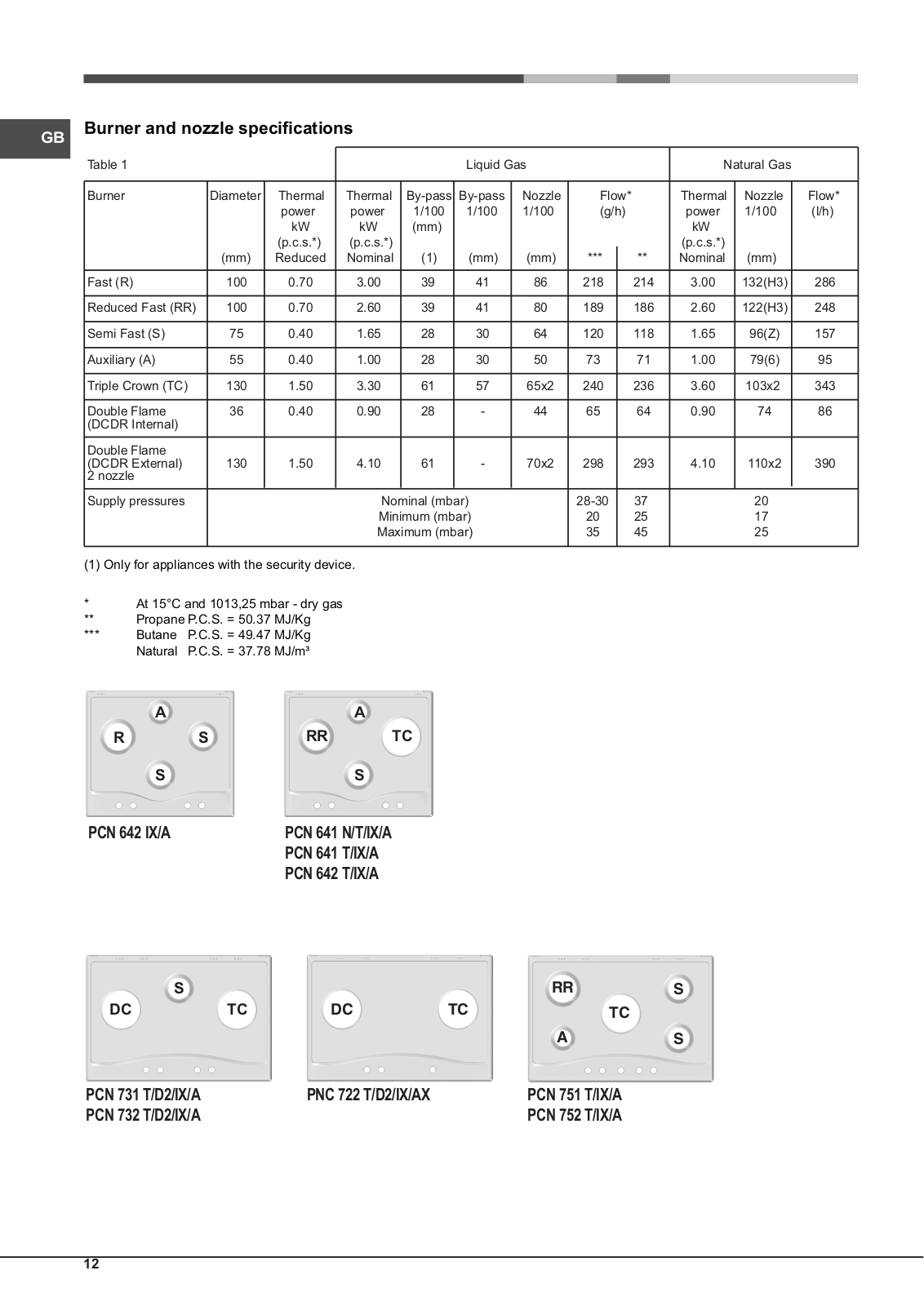
PCN 731 T/D2/IX/A
PCN 732 T/D2/IX/A
PCN 751 T/IX/A
PCN 751 T/IX/H
2
PCN 751 T/IX/HA
PCN 752 T/AS/HA
PCN 752 T/EX/HA
PCN 752 T/HA
PCN 752 T/IX/A
PCN 752 T/IX/A IL
PCN 752 T/IX/HA
PCN 752 T/IX/HA NK
PCN 752 T/IX/HAR
PCN 752 U/IX/H
2
PCN 752 U/IX/HA
PCN 752 U/IX/HA NK
PCN 761 S/IX/A
PCN 762 S/IX/HA
PCN 762 S/IX/HAR
PCT 64 F L SS
PDMW 45
Loading...
Loading...
Nothing found
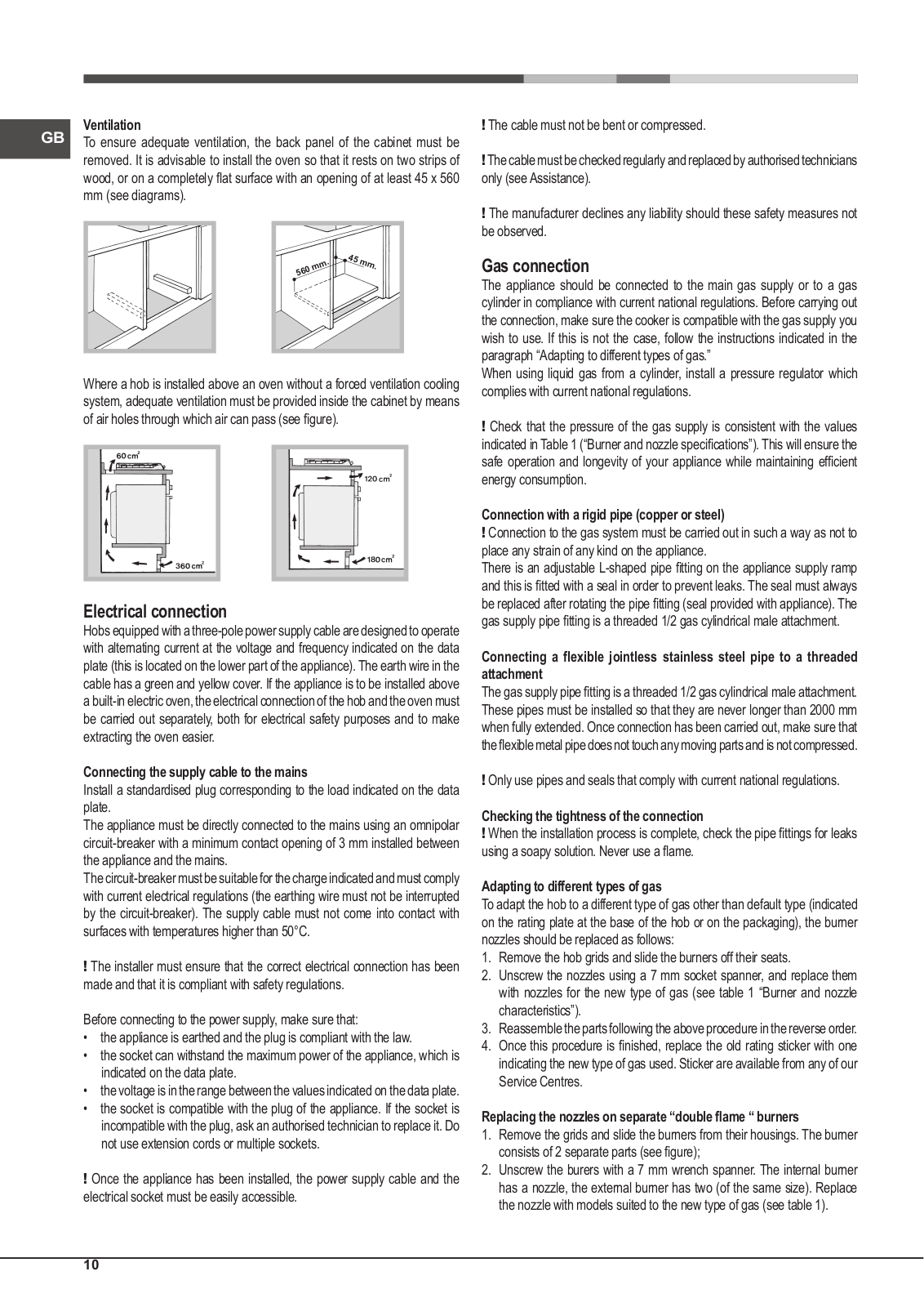
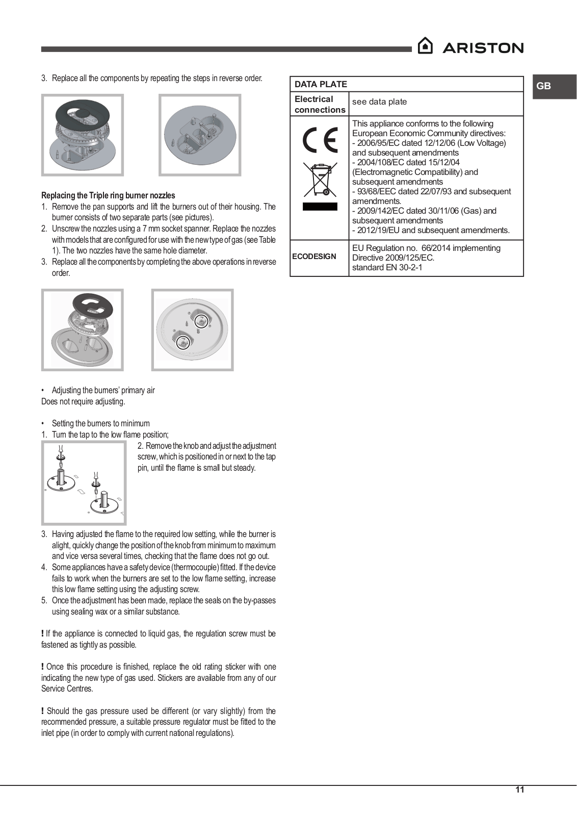
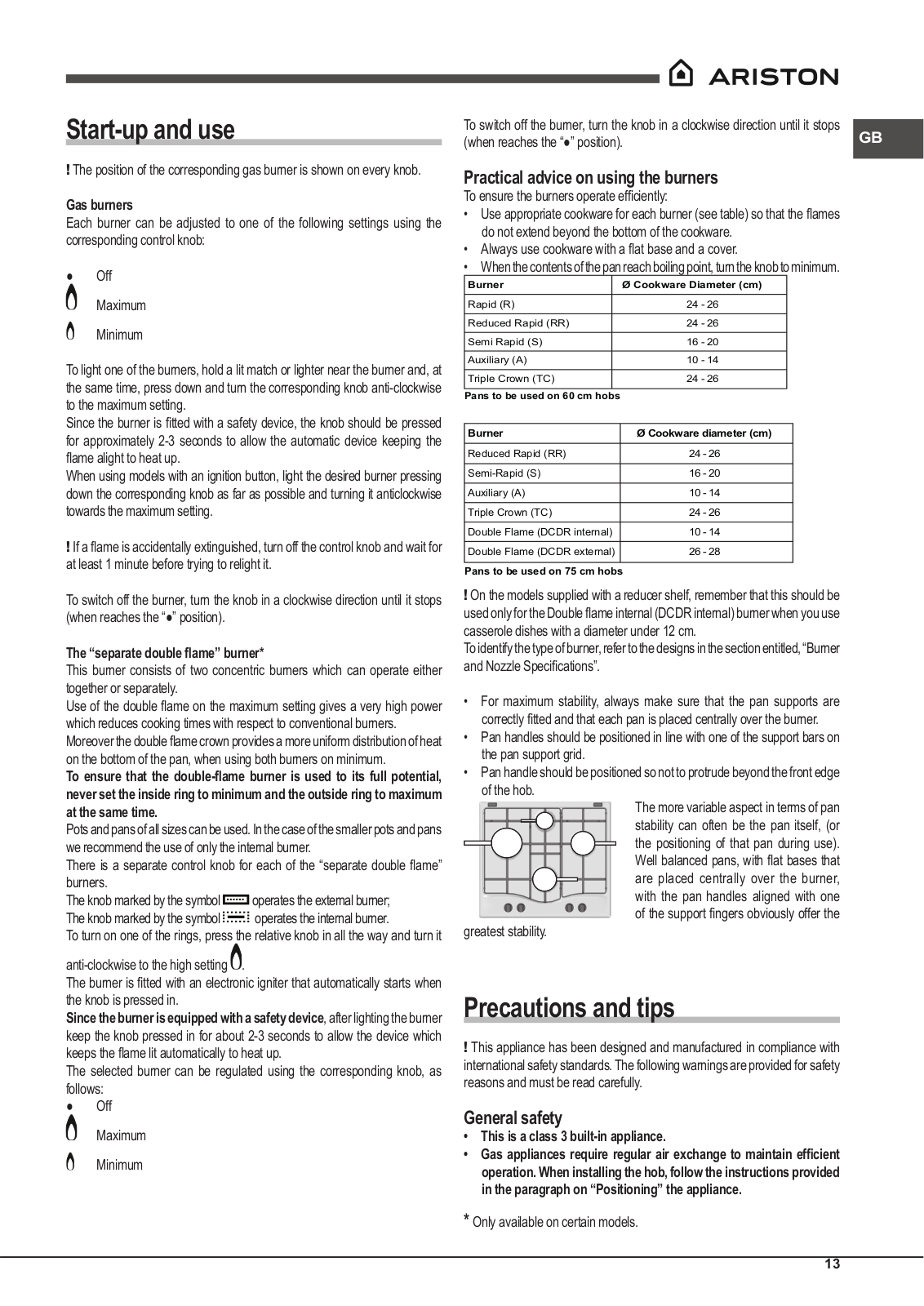
PCN 641 N/T/IX/A
User Manual
56 pgs
10.24 Mb
0
Table of contents
Loading...
Hotpoint PCN 641 N/T/IX/A, PCN 642 IX/A User Manual
...
Hotpoint User Manual
Download
Specifications and Main Features
Frequently Asked Questions
User Manual
Download
Loading...
+
39
hidden pages
Unhide
You need points to download manuals.
1 point = 1 manual.
You can buy points or you can get point for every manual you upload.
Buy points
Upload your manuals
 Loading...