How it Works
Log In / Sign Up
Buy Points
How it Works
FAQ
Contact Us
Questions and Suggestions
Users
Hotpoint
Loading...
M
MWHC 1331 FW
MWHF 201 B
MWHF 203 B
MWHZ33
MWK211KHA
MWK212XHA
MWK 422 X
MWK422XHAS
Mwk434HAX
MWKX222HAX
MWKX 222 X HA
MWX 431.1 X
MZ 1
MZA 1
MZAA 1
N
N321IX
NBXR333
NBXR333EG0WW
2
NBXR333EG1WW
2
NBXR333EG2WW
2
NBXR333EG3WW
2
NBXR333EG4WW
2
NBXR333EG5WW
2
NBXR333EG6WW
2
NBXR333EG7WW
2
NBXR333GG0WW
2
NBXR333GG1WW
2
NBXR333GG2WW
2
NBXR333GG3WW
2
NBXR333GG4WW
2
NBXR333GG5WW
2
NBXR333GG6WW
2
NBXR333GG7WW
NBXR333GG8WW
2
NBXR453EV0WW
NBXR453EVAA
NBXR453EVWW
NBXR453GVAA
NBXR453GVWW
NBXR463
NBXR463EB3WW
2
NCD 191 I
NEBL1 20402 V D AI
NEBY 20410 V
NEBY 20420 V
NEBYH 18242 F
NEM 645 D C
NEM 645 D X
NFFUD 191 X
28
NFFUD 191 X.1
NIC 641 B
NIO 632 CP C AUS
NIO 844 DO B AUS
NIO 844 DO B AUS S
NIX 644 B E
NJSR453EW1WW
NJSR453EWWW
NKXR473ET0WW
NKXR473ET2WW
NKXR473ET3WW
NKXR473ET5WW
NKXR473GT0WW
NKXR473GT2WW
NKXR473GT3WW
NKXR473GT5WW
NLCD 1164 D AW UK N
NLL113
NLL113EY0WO
NLL113EY4WO
NLL113EYWO
NLLCD 1044 WD AW UK N
NLLCD 1045 WD AW UK
2
NLLCD 1064 DGD AW UK N
NLLCD 1065 DGD AW UK
2
NLLCD 1165 WD ADW UK
2
NLLCD 947 WD ADW UK
2
NLLR113EVWW
NM10 844 GS UK
2
NM10 844 WW UK
2
NM10 944 GS UK
2
NM10 944 WS UK
2
NM10 944 WW UK
2
NM11 1044 WC A UK N
NM11 1045 WC A UK
2
NM11 1064 WC A UK N
NM11 1065 WC A UK
2
NM11 844 GS UK N
NM11 844 WC A UK N
NM11 844 WW UK N
NM11 845 GC A UK
2
NM11 845 WC A UK
2
NM11 945 BC A UK N
NM11 945 GC A UK N
NM11 945 GS UK N
NM11 945 WC A UK N
NM11 945 WS A UK N
NM11 945 WW UK N
NM11 946 BC A UK
2
NM11 946 GC A UK
2
NM11 946 WC A UK
2
Loading...
Loading...
Nothing found
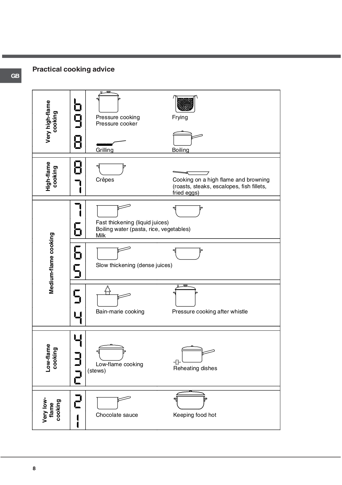
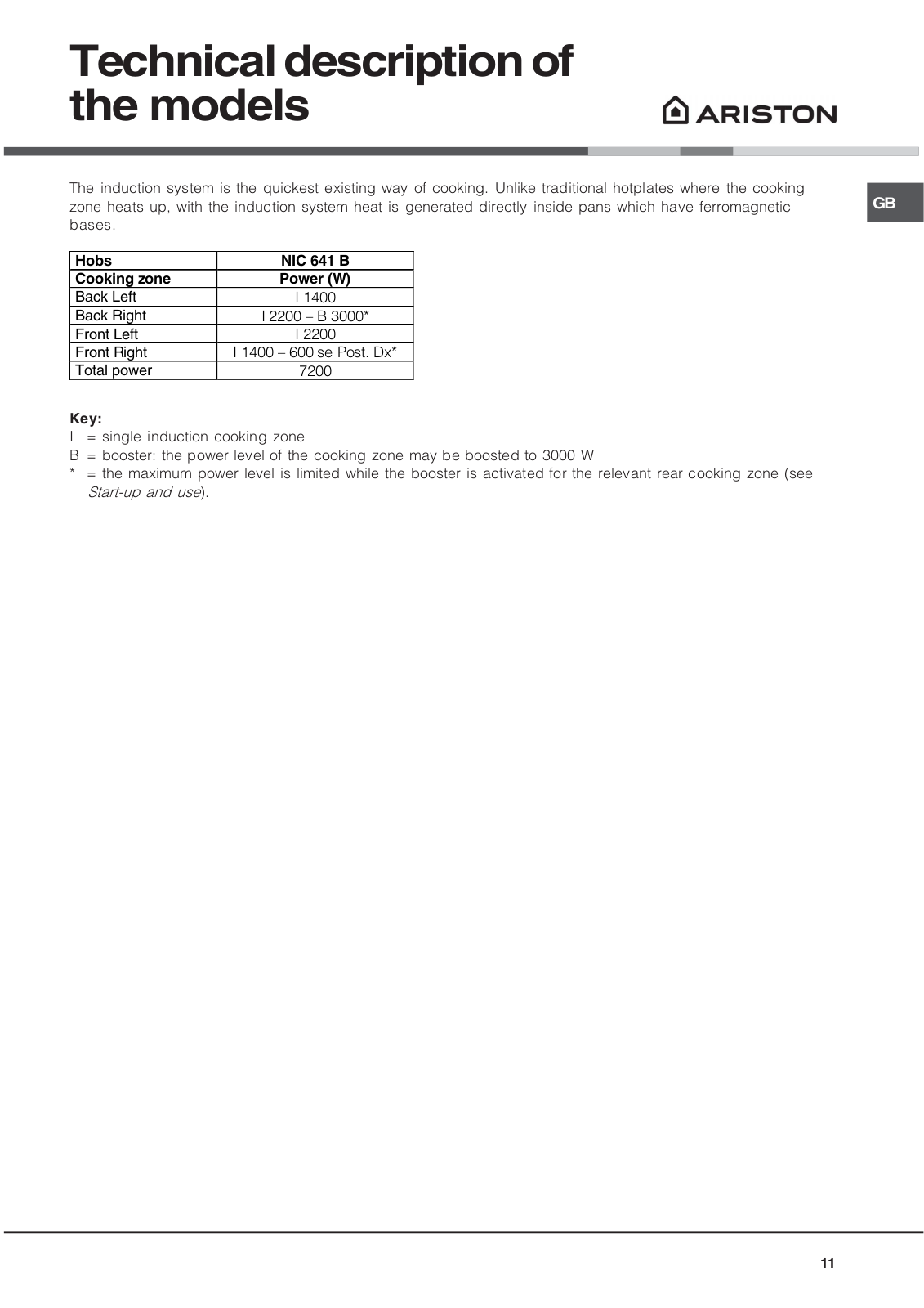
NIC 641 B
User Manual
56 pgs
1.71 Mb
0
Table of contents
Loading...
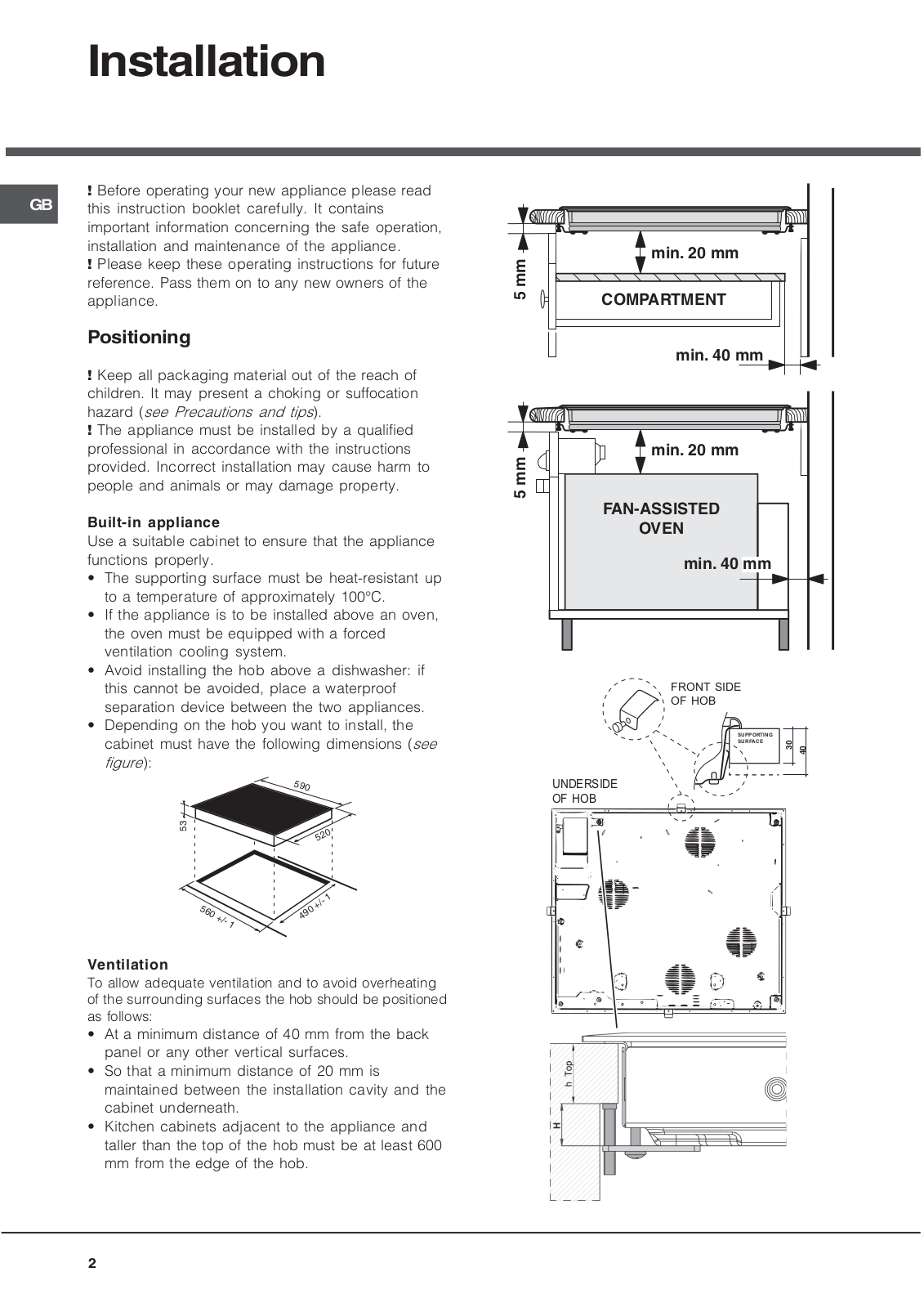
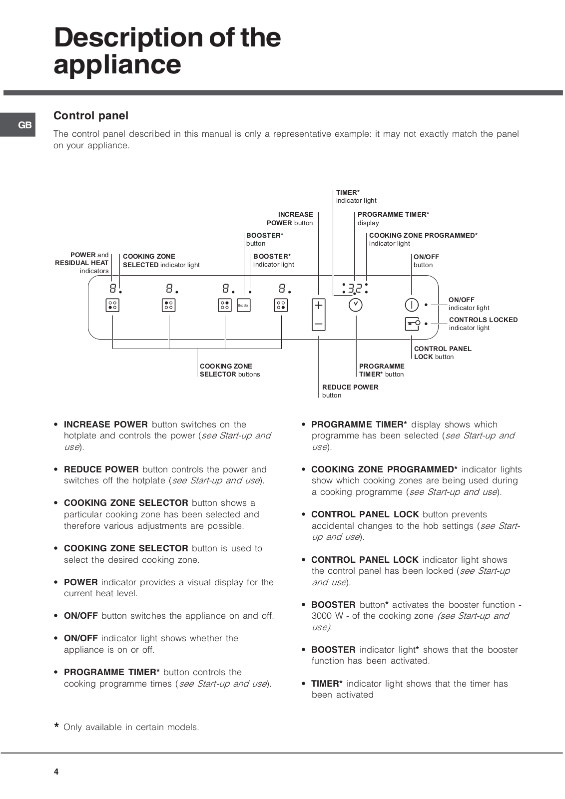
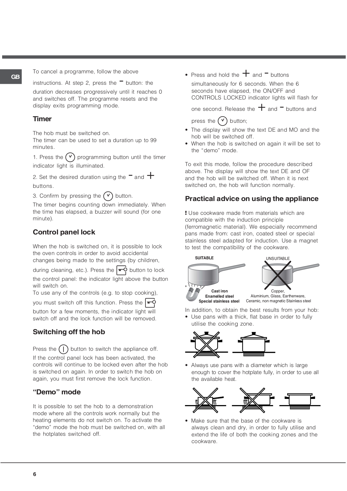
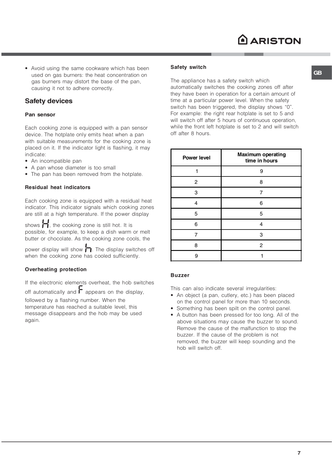
Hotpoint NIC 641 B User Manual
...
Hotpoint User Manual
Download
Loading...
+
39
hidden pages
Unhide
You need points to download manuals.
1 point = 1 manual.
You can buy points or you can get point for every manual you upload.
Buy points
Upload your manuals
 Loading...