

Hotpoint MSZ900DFUK, MSZ902DFUK, MSZ906DFUK, MSZ906NDFUK, MSZ900NDFUK Service Information
...
Indesit Company UK Ltd
© 2012 Reg. Office: Peterborough PE2 9JB Registered in London: 106725
Service
Information
HOTPOINT
SIDE-BY-SIDE
FRIDGE
FREEZERS
(7 ~ Segment Version)
Models Comm.
Covered Code
Energy Band 'A' Models
MSZ900DFUK 71629
MSZ902DFUK 71622
MSZ906DFUK 71630
MSZ900NDFUK 76246
MSZ902NDFUK 76244
MSZ906NDFUK 76240
5407573 Issue 2 March 2012

2 of 61
Service Manual UK
Indesit
Company
English
HEALTH AND SAFETY
For the servicing of refrigeration products, containing R134a refrigerant.
These instructions are in addition to any other Company procedures already published.
Published primarily for Indesit Company engineers working in the UK or Southern Ireland, for
which these instructions are MANDATORY.
General
1. This manual is not intended as a comprehensive repair/maintenance guide to the appliance.
2. It should only be used by suitably qualified persons having technical competence, applicable product
knowledge, suitable tools and test equipment.
3. Servicing of electrical appliances must be undertaken with the appliance disconnected. (unplugged
from the electrical supply).
4. Servicing must be preceded by earth continuity and insulation checks.
5. Personal safety precautions must be taken to protect against accidents caused by sharp edges on
metal and plastic parts.
6. After servicing, the appliance must be rechecked for electrical safety.
Refrigerant R134a - Safe Handling - Transporting & Storage
1. Work areas should be well ventilated and any immediate heat sources turned off.
2. Do not smoke where there is a possibility of refrigerant in the atmosphere. Customer/s should also
be advised.
3. Cylinders must not have heat applied, or stand close to a heat source, and should be stored out of
direct sunlight.
4. Should a sudden release of refrigerant occur, open windows or outside doors in the immediate
vicinity, then evacuate for a few minutes.
5. It is illegal to intentionally vent R134a refrigerant to atmosphere. Follow the company procedure on
collection and reclamation.
6. If a leak is identified the appliance must be repaired immediately if possible.
7. Where it is not possible to repair the appliance immediately the customer should be advised:
Appliance should be turned off and the refrigerant recovered.
8. Returned compressors must be sealed to prevent the escape of oil and refrigerant. Refer to the
Environmental responsibilities for service engineers in your Health and Safety booklet.
9. Cylinders (R134a) being transported must be in an upright position on the floor of the vehicle and
prevented from movement.
10. A green compressed gas label Part No. 8100062 should be displayed on the rear of the vehicle.
3 of 61
Indesit Company
Service Manual UK English
CONTENTS
Health & Safety . . . . . . . . . . . . . . . . . . . . . . . . . . . . . . . . . . . . . . . . . . . . . . . . . . . . . . . 2
Star Rating . . . . . . . . . . . . . . . . . . . . . . . . . . . . . . . . . . . . . . . . . . . . . . . . . . . . . . . . . . .4
Introduction . . . . . . . . . . . . . . . . . . . . . . . . . . . . . . . . . . . . . . . . . . . . . . . . . . . . . . . . . . 5
Specifications . . . . . . . . . . . . . . . . . . . . . . . . . . . . . . . . . . . . . . . . . . . . . . . . . . . . . 6 - 7
Appliance Dimensions . . . . . . . . . . . . . . . . . . . . . . . . . . . . . . . . . . . . . . . . . . . . . . . . . 8
Removing the Appliance Furniture . . . . . . . . . . . . . . . . . . . . . . . . . . . . . . . . . . . . . . . 9
Detailed Views . . . . . . . . . . . . . . . . . . . . . . . . . . . . . . . . . . . . . . . . . . . . . . . . . . . 10 - 11
Water Filter. . . . . . . . . . . . . . . . . . . . . . . . . . . . . . . . . . . . . . . . . . . . . . . . . . . . . . . . . . 12
Ice Maker Operation & Water Flow System . . . . . . . . . . . . . . . . . . . . . . . . . . . 13 - 20
Power Module Parameters . . . . . . . . . . . . . . . . . . . . . . . . . . . . . . . . . . . . . . . . . 21 - 22
Display Panel Functions & Descriptions . . . . . . . . . . . . . . . . . . . . . . . . . . . . . 23 - 27
Component Functions . . . . . . . . . . . . . . . . . . . . . . . . . . . . . . . . . . . . . . . . . . . . 28 - 30
Alarm Conditions, Temperature Tables & Auto Test . . . . . . . . . . . . . . . . . . . . 31 - 35
Ice Maker & Ice Dispensing Troubleshooting. . . . . . . . . . . . . . . . . . . . . . . . . . 36 - 38
Air Flow . . . . . . . . . . . . . . . . . . . . . . . . . . . . . . . . . . . . . . . . . . . . . . . . . . . . . . . . 39 - 40
Thermistor (NTC) Sensor Location . . . . . . . . . . . . . . . . . . . . . . . . . . . . . . . . . . . . . . 41
Servicing & Dismantling Instructions . . . . . . . . . . . . . . . . . . . . . . . . . . . . . . . . 42 - 49
Boards . . . . . . . . . . . . . . . . . . . . . . . . . . . . . . . . . . . . . . . . . . . . . . . . . . . . . . . . . . . . .50
Compressor Connection Chart . . . . . . . . . . . . . . . . . . . . . . . . . . . . . . . . . . . . . . . . . 51
Power Module Edge Connections . . . . . . . . . . . . . . . . . . . . . . . . . . . . . . . . . . . 52 - 53
Theoretical Wiring Diagrams . . . . . . . . . . . . . . . . . . . . . . . . . . . . . . . . . . . . . . . 54 - 55
Installation Instructions . . . . . . . . . . . . . . . . . . . . . . . . . . . . . . . . . . . . . . . . . . . 56 - 60
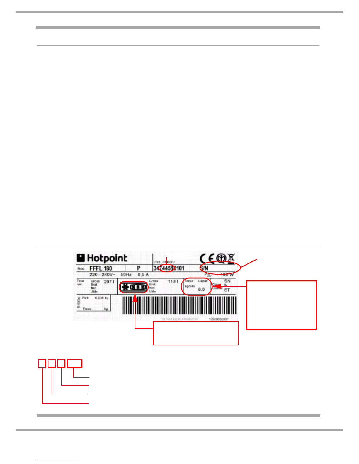
PRODUCT IDENTITY
Example
1 Commercial Code: 74451
2 Serial Number:
Printed on a separate label below the Rating Plate
Build number that day, e.g. 8689th built
Day of manufacture, e.g. 10
th
of month
Month of manufacture, e.g. June
Year of manufacture, e.g. 2010
1
2
00610 8689
006108689
Example Shown:
This appliance is rated as 4 star
indicated by the logo
Example shown:
This appliance has the
capacity to freeze 6 kg of
fresh food from +25°C to
-18°C in 24 hours without
affecting the frozen food
already being stored.
4 of 61
Service Manual UK
Indesit
Company
English
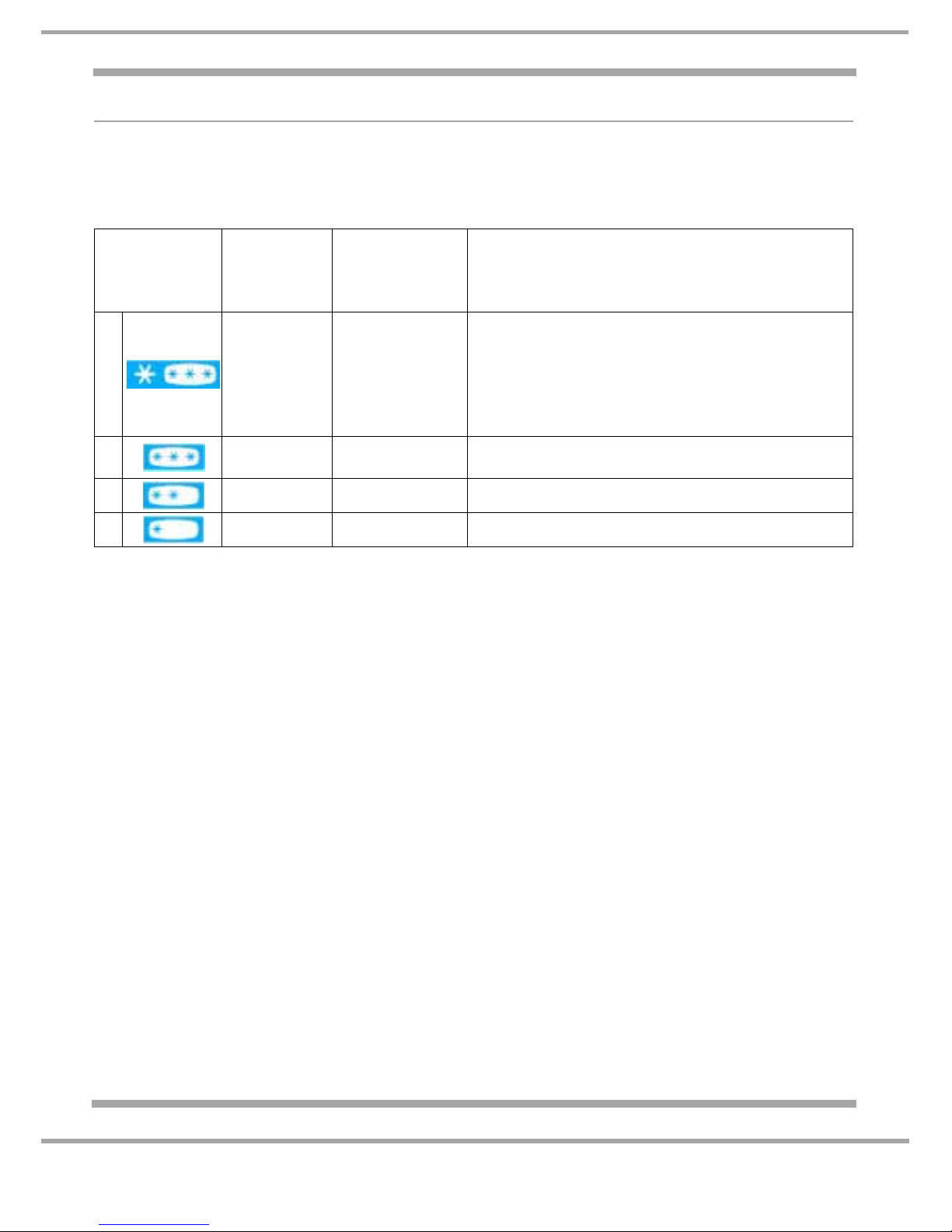
STAR RATING
UK and EU freezers and refrigerators with freezer compartments are star rated with regard to their
capacity to store or freeze food.
The temperatures for the freezer compartment relating to these star ratings are as follows:
Although both the three and four star ratings specify the same storage times and same minimum
temperature of -18°C, only a four star freezer is intended to be used for freezing fresh food, and may
include a 'fast freeze' function (runs the compressor continually, down to as low as -26°C) to facilitate
this.
Three (or fewer) stars are used for frozen food compartments which are only suitable for storing frozen
food; introducing fresh food into such a compartment is likely to result in unacceptable temperature
rises.
This difference in categorisation is shown in the design of the star logo, where the 'standard' three stars
are displayed in a box using 'positive' colours, denoting the same normal operation as a 3-star freezer,
and the fourth star showing the additional fresh food/fast freeze function is prefixed to the box in
'negative' colours or with other distinct formatting.
STAR Rating
Minimum
Temperature
°C (°F)
Maximum
Storage Time for
Per-Frozen
Foods
Maximum Storage Time for Frozen from Fresh
Foods
4 -18°C (0°F)
Between 3 and 12
months
Between 3 and 12 months.
Has the capacity to freeze a specified quantity of fresh
food from +25°C to -18°C in 24 hours
without affecting the frozen food already being stored.
(Refer to the rating plate on the appliance for
specific quantity.)
3 -18°C (0°F)
Between 3 and 12
months
N/A
2 -12°C (10°C) 1 month N/A
1 -6°C (21°F) 1 week N/A

5 of 61
Indesit Company
Service Manual UK English
MODEL INTRODUCTION
The models included in this manual are 1774 mm high Side by Side fridge and freezer, one
compressor Frost Free appliances. There are two different ranges of the same model, the first range
was first introduced during March 2010 and the second range during September 2011. All models are
similar with regard to the furniture design, refer to Technical Specification Pages 6 and 7 for the
models, colour variants and specifications. The two ranges are referred to in this manual as either
2010 DF Models or 2011 NDF models. Where no specific range is noted, the information will be
generic for both ranges.
Interior:
The interior of the fridge has safety glass shelves, one meat drawer (chiller) and one humidity
controlled salad bin (crisper) with a glass cover. The door has two deep shelves, a dairy shelf with a lid
and a lower bottle shelf.
The interior of the freezer section has two drawers of varying sizes and two safety glass shelves of
varying sizes. The door has two commodity shelves and an ice storage bucket.
The interior differences between the DF and NDF model are shown below:
MSZ900DF, MSZ902DF and MSZ906DF (2010 DF Models):
1. The Icemaker (with blue rake) is located at the top inside section of the freezer compartment.
2. Has two roller wheels at the rear and two wheels and two adjustable feet at the front.
MSZ900NDF, MSZ902NDF and MSZ906NDF (2011 NDF Models)
1. Sankyo IDI2 (In-Door-Ice) Icemaker is located in the freezer door above the ice storage bucket.
2. A new upper hinge with “cut-out” for a door removal without removing the connectors and modified
top connectors with pin lock system.
3. New water piping guidance for the ice maker. Both pipes are now located in the base of the
appliance. Blue pipe for the ice-maker. Transparent pipe for the water.
4. Has two feet at the rear and two feet at front.
5. Has an ice maker fill tube heater.
6. LED light in the water dispensing area.
The appliance is 'frost free' design so defrosting is automatic.
The digital display interface module (7 ~ segment LED) is mounted in the front of the freezer door with
the drinks dispenser, the fast freeze button and ice maker controls are also mounted in the same area.
The fridge and freezer temperature settings are adjusted by selecting the + / - buttons next to the
relevant temperature display window. All functions are monitored and actioned by the power module
mounted at the rear of the appliance within the compressor compartment.
The climate class is N / ST signifying that it is designed to operate in ambient temperatures between
+16°C to +38°C.
As with many refrigeration appliances, it is important that it is installed and operated within the
recommended ambient temperature range and that there is adequate ventilation.
All appliances equipped with an automatic ice-maker and water dispenser must be connected to a
water supply that only delivers drinking water. See Specification page for pressure requirements.
6 of 61
Service Manual UK
Indesit
Company
English
SPECIFICATIONS
Key: DF = Ice and Water Dispenser
GENERAL:
Appliance Type: Side by Side
Static / Frost Free: Frost Free
Door Hinging - Freezer L/H & Fridge R/H
Reversible: No
Plug/Cable: UK / 2.45m
Water Pipe: 1.65m
Noise Level: 'A' Class band models ~ 45dB
Climate Class: (Rating Plate) N.ST = 16°C to 38°C
Star Rating 4 Star
Refrigeration Type: Frost Free - Fin On Tube (FOT)
DIMENSIONS & WEIGHT:
*Height - Maximum: 1775 mm 1744 mm rear cabinet height only
*Width: 902 mm
*Depth: 752 mm
Weight Gross: 146 kg
Weight Net: 140 kg
To allow product handling and sufficient air circulation, leave at least 10 mm clearance at the sides,
above the appliance and between the rear panel and the wall.
* For further dimensions please refer to Page 8.
CAPACITIES / VOLUME: Gross Volume Net Volume
Fridge: 340 litre 335 litre
Freezer: 206 litre 155 litre
Freezing Capacities (per 24 hrs):12 kg
Conservation Time: 5 hours
Model Colours
Commercial
Code
Manufactured
Introduction
Date
MSZ906DF Black 71630 Italy March 2010
MSZ900DF Silver 71629 Italy March 2010
MSZ902DF Stainless Steel 71622 Italy March 2010
MSZ900NDFUK Silver 76246 Italy Sept. 2011
MSZ902NDFUK Stainless Steel 76244 Italy Sept. 2011
MSZ906NDFUK Black 76240 Italy Sept. 2011
7 of 61
Indesit Company
Service Manual UK English
TECHNICAL DATA:
Power Supply Voltage: 220/240 V
Power Supply Frequency: 50 Hz
Mains Water Supply: Min. 1.38 bar
Max. 8.27 bar
Freezer Lamp: T-Click 40W 220V - 240V
Fridge Lamp: T-Click 40W 220V - 240V
ENERGY
Energy Class: A
Power Consumption: 1.39 kWh/24hr
Annual Consumption: 507.35 kWh/yr
COMPRESSOR WINDING
Manufacturer: Embraco
Type I/D: EGYS 90 HLP
Winding Resistance: Start: 21.3:
Run: 12.3:
Refrigerant/ Grams: R134a / 160g - Refer to the appliance rating plate
Insulation: C-Pentane
HEATER RESISTANCES
Evaporator Defrost Heater: 86:
Ice Maker (2010 DF Models):
Motor Power 8W
Sankyo IDI (2011 NDF Models):
Fill Tube Heater: 65.85 - 73.17:
Motor Power: 2W
ICE PRODUCTION:
ICEMAKER SANKYO IDI (IDI= In Door Ice) located in the freezer door of 2011 NDF models:
Approximately six or seven loads or 0.8kg.
ICEMAKER (2010 DF Models): Approximately 200 ice cubes per 24 hours running at optimum capacity
COMPONENT RESISTANCES
Condenser Fan Motor: 220 - 240V, 1100 rpm
Evaporator Fan Motor: 256:
Water Dispenser Solenoid Valve: 8.68k:
Water Ice Maker Solenoid Valve: 8.71k:
Ice Chute Motor (Dispenser) 50: ± 7%

8 of 61
Service Manual UK
Indesit
Company
English
DIMENSIONS
Dimensions are an approximate guidance as doors can be adjusted horizontally and vertically.
PLAN VIEW DIMENSIONS (mm)
Door opening with Handle (Fridge Side, door in relaxed natural open position.
NOTE: - To allow full removal of the two lower drawers and shelves, the door
requires further opening past the relaxed natural stop position.
270
Maximum door opening with Handle (Fridge Side, door fully open pushed past
its stop position to allow full removal of the two lower drawers and shelves).
312 as shown in PLAN VIEW above
Tot al Depth including Handles 780
Total Depth without Handles (Fridge Side) 700 (cabinet 598 + door 90 + rear panel 12)
Tot al Depth including Dispenser but without Handles (Freezer Side) 705 (cabinet 598 + dispenser 5 + rear panel 12 + door 90)
Tot al Depth of Cabinet without Doors 610 (cabinet 598 + rear panel 12)
Total Height of Cabinet without Upper Hinges and Doors 1744
Total Height of Cabinet including Upper Hinges and Doors 1755
APERTURE MEASUREMENTS PLAN VIEW
(With door open 90° and fully)(Measurements below are the minimum requirement in mm.
Dimensions include the 10 mm space required on both
sides, back and above)
355
922
1754
620
410
1064
902
240
82
7
312
88
7
1137
9 of 61
Indesit Company
Service Manual UK English
REMOVING THE REFRIGERATOR & FREEZER FURNITURE
Removing the Fridge and Freezer Shelves
1. Pull the shelf out until it reaches its stop point then lift the shelf from the front to remove it.
2. NOTE: - For the easiest recommended removal of some fridge shelves and drawers, lift the front
end up to nearly a vertical position whilst pushing the fridge door fully open.
Removing the Crisper or Meat Drawer from the Fridge Compartment
1. Slide the drawer out until it reaches its stop;
2. With one hand underneath the drawer, lift from the front and pull it past the stops; the drawer will
come off the runners and can be pulled out further;
3. To remove it completely, lift the front end up (rear end down) and turn and manoeuvre the drawer
out. NOTE: The fridge door may require pushing to its fully open position.
Crisper Moisture Control Device
• Moving the slider to the far right opens the small vent, eliminating
humidity from the compartment. this setting is best for preserving
fruits and vegetables with skin.
• Moving the slider to the far left closes the small vent, maintaining
humidity inside the compartment. This setting is best for preserving
salads and leaf vegetables.
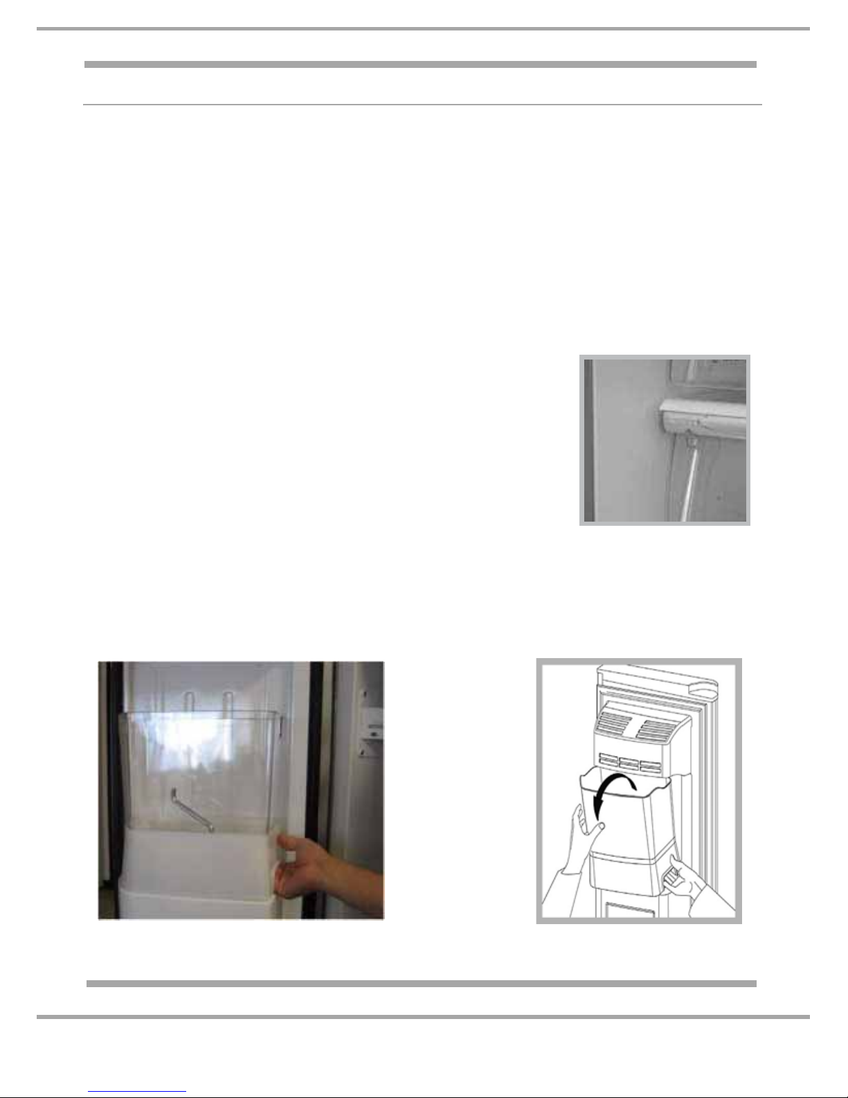
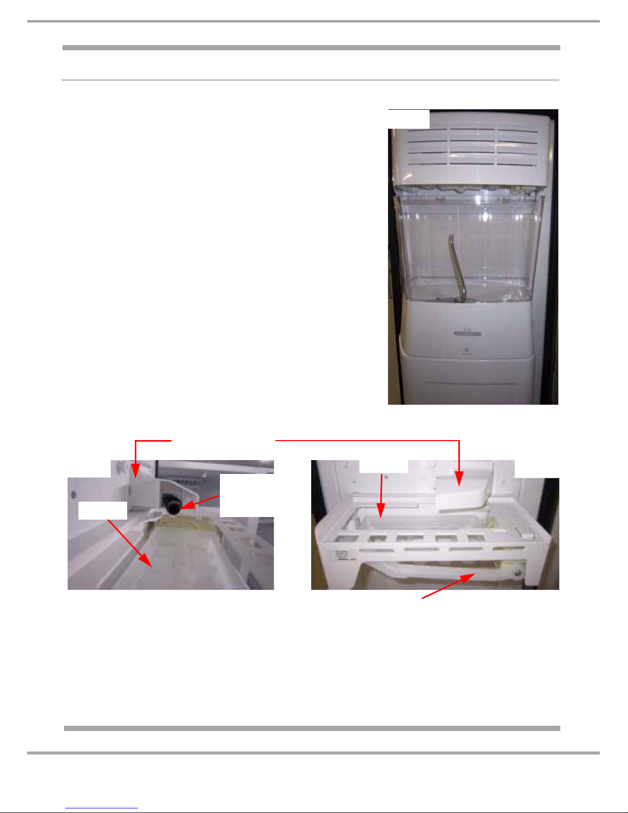
Removing the Ice Storage Bucket / Container
Locate the handle inside the opening at the base of the container (right hand side). Pull the lever and lift
the container upwards and outwards (see Figs. A and B). To reposition it, rest the base of the container
on the ledge in the inner door and lower it into position. Note: Switch the icemaker off before removing
the container to prevent accidental discharge of ice cubes.
Fig. A
Fig. B
2010 DF MODELS 2011 NDF MODELS
10 of 61
Service Manual UK
Indesit
Company
English
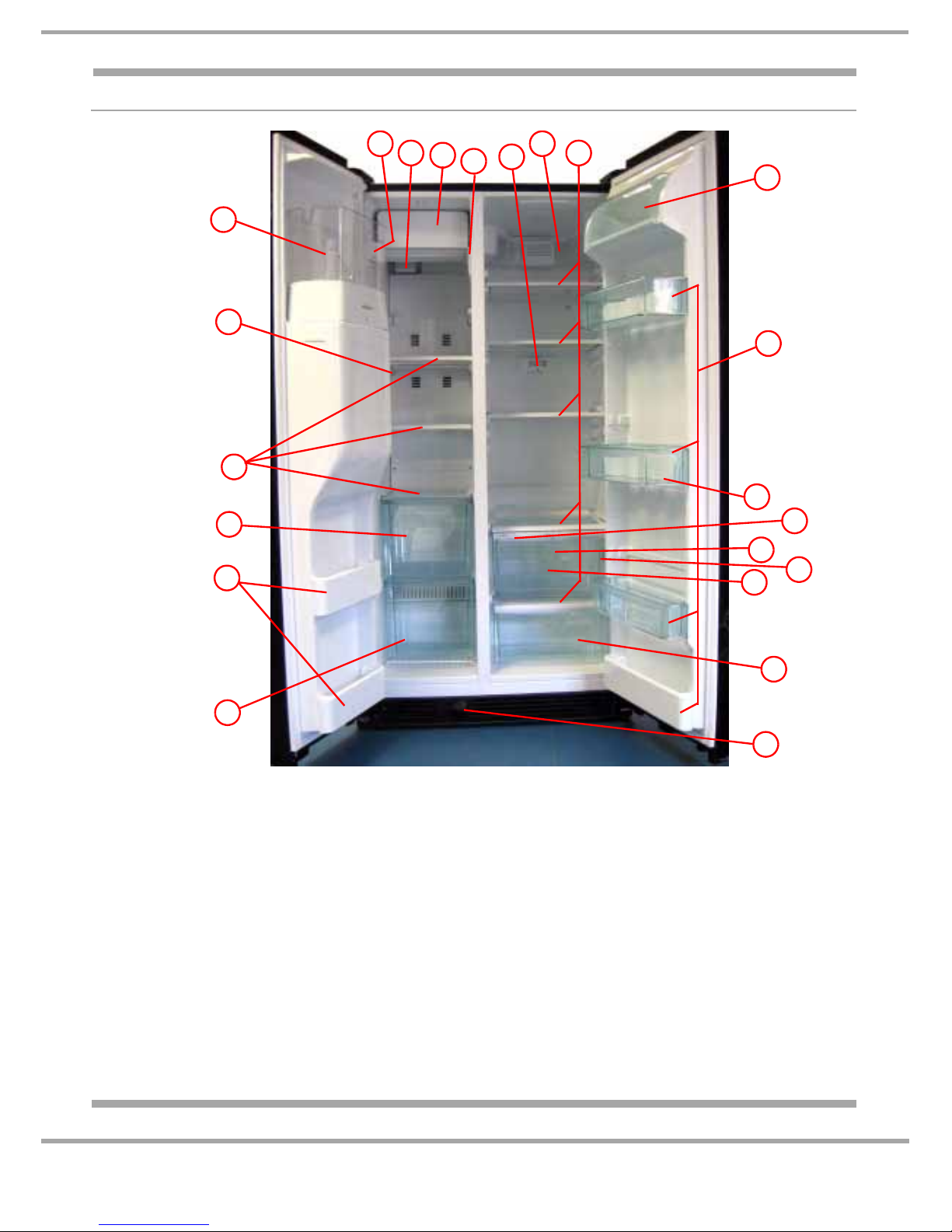
2010 DF MODELS
Refrigeration Compartment Freezer Compartment
A. Interior light located within the damper
housing/light box
B. Shelves
C. Fridge sensor support
D. Crisper drawer moisture control
E. Crisper drawer
F. Rating plate located on inner fridge liner
G. Water tube (coiled reservoir part of the
water tube located on back wall behind
crisper drawer
H. Meat/chiller drawer
I. Dairy compartment
J. Door bottle shelves
K. Door shelf bottle separator
L. Water filter
M. Automatic icemaker located behind cover
N. Interior light located on the back wall
O. Icemaker emitter (left liner)
P. Icemaker receiver (right liner)
Q. Ice cube container/bucket and auger
R. Freezer sensor on left freezer liner
S. Glass shelves
T. Drawer (upper)
U. Drawer (lower)
V. Door shelves
A
C
M
N
O
Q
R
S
T
V
U
J
K
E
F
G
H
D
I
B
DETAILEDVIEW
P
L
11 of 61
Indesit Company
Service Manual UK English
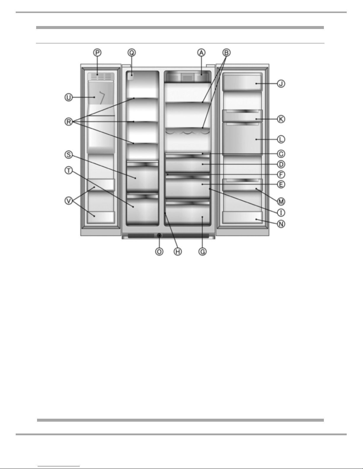
2011 NDF MODELS
Refrigeration Compartment Freezer Compartment
A. Inside light
B. Shelves
C. Shelf - drawer lid
D. Snack drawer (depending on model)
E. Crisper drawer
F. crisper drawer moisture control (where provided)
G. Meat / crisper drawer
H. Meat / cripers drawer temperature control (where
provided)
I. Rating plate
J. Dairy compartment
K. Door trays
L. Fresh compartment and Nature Fresh (where
provided)
M. 2 litre door tray with bottle holder (where
provided)
N. 0.75 litre door tray
O. Water filter (depending on model)
P. Automatic ice maker
Q. Inside light
R. Glass shelves / racks (depending on model)
S. Drawer / top basket (depending on model)
T. Drawer / bottom basket (depending on model)
U. Ice container
V. Door trays
12 of 61
Service Manual UK
Indesit
Company
English
WATER FILTER
REMOVAL OF THE FILTER
1. Locate the water filter cartridge cap in the base plinth grille below the freezer compartment door.
Rotate the cap counter clockwise to a vertical position (¼ turn) and pull the cap and filter cartridge
from the filter housing out through the base grille.
Note: Since there is water in the cartridge, some spilling may occur.
2. Remove the cartridge cap by sliding it off the end of the old cartridge.
DO NOT DISCARD THE CAP.
3. Take the new cartridge out of its packaging and remove the protective cover from the O-rings.
Make a note of the installation date in the space provided on the new cartridge.
4. Slide the cartridge cap onto the new cartridge.
5. With the cartridge cap in the vertical position, push the new filter cartridge into the base grille until
it stops. Rotate the cartridge cap clockwise to a horizontal position (¼ turn).
6. RUN WATER THROUGH THE DISPENSER UNTIL THE WATER RUNS CLEAR (about 9-14 litres
or 6-7 minutes). This will clean the system and clear air from the lines. Note: As air is cleared from
the system, water may spurt out of the dispenser.
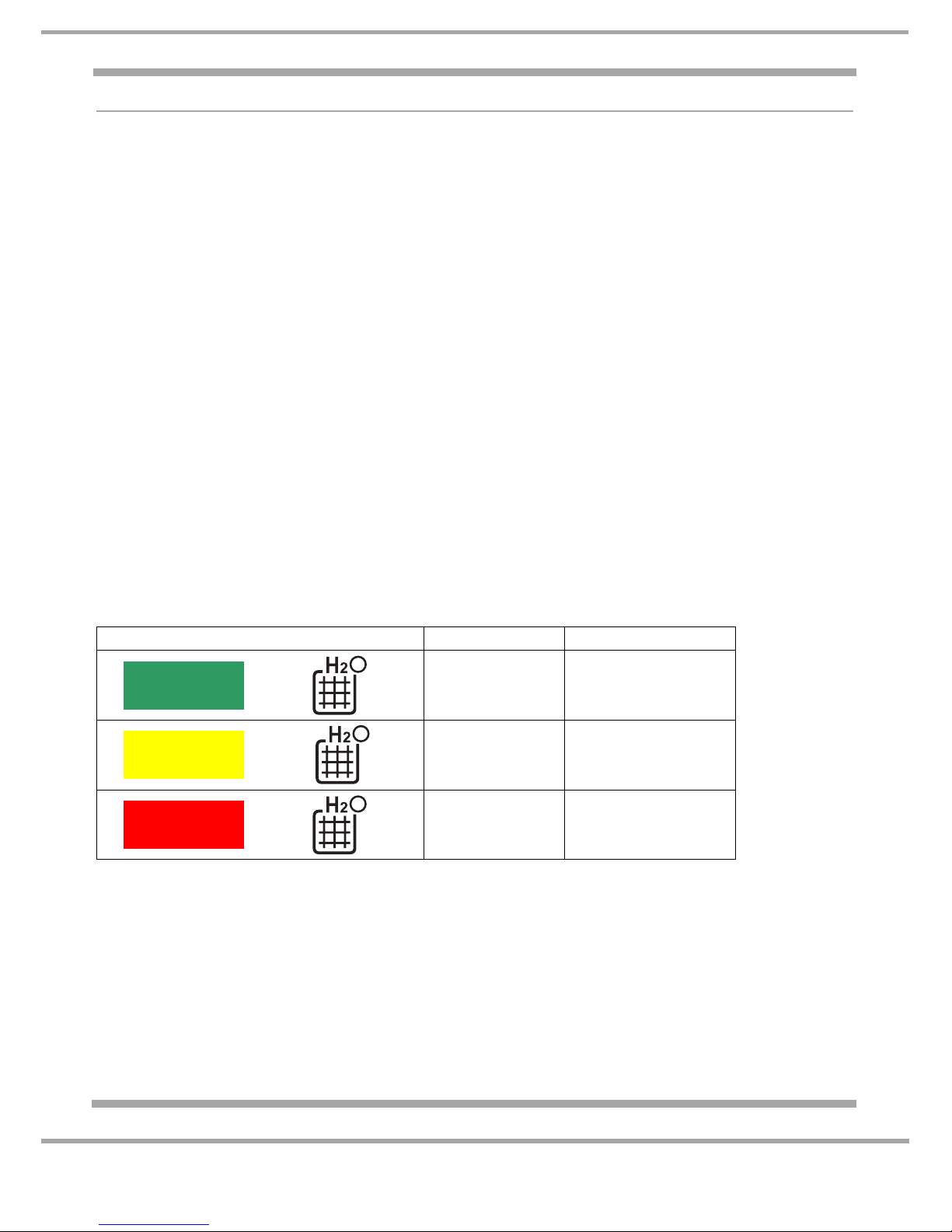
OPERATION
The water filter control will calculate and record the total volume of water flowed through the valve
during the opening periods. The flow rate for the dispenser water valve is 1.51 litres per minute
(24-58 cc per second).
The total litres flow is calculated by using the flow rates for Ice Maker valve and Water Dispenser
valve. The valve flow rate in litres is multiplied by the corresponding open time. The total litres will be
obtained adding the litres of each valve. The litres and time usage data will be recorded even after a
power black out. This data is updated daily. The table below shows the relationship between water flow
and time. The H
2
O symbol located on the user interface changes colour accordingly.
The MID Yellow usage state indicates that the filter is almost exhausted and the user should order a
new filter. When the filter indicator is in its RED alarm usage state the filter should be changed.
Once the filter has been changed the user should press the 'RESET' button on the display panel for at
least 3 seconds until the audible beep sounds. The water filter icon switches back to the low usage
state. This normal RESET operation will not work in the LOW Green usage state. It is however
possible to reset the water filter during any of the usage states after an autotest if the filter was
changed during the green stage (refer to Page 34 for the Autotest). When the autotest has finished,
indicated by 00 in the display, press the water dispenser paddle 4 times (within 10 seconds).
The symbol F will display on the fridge side to confirm the operation. If an alarm error code is displayed
it will cycle together with the F symbol.
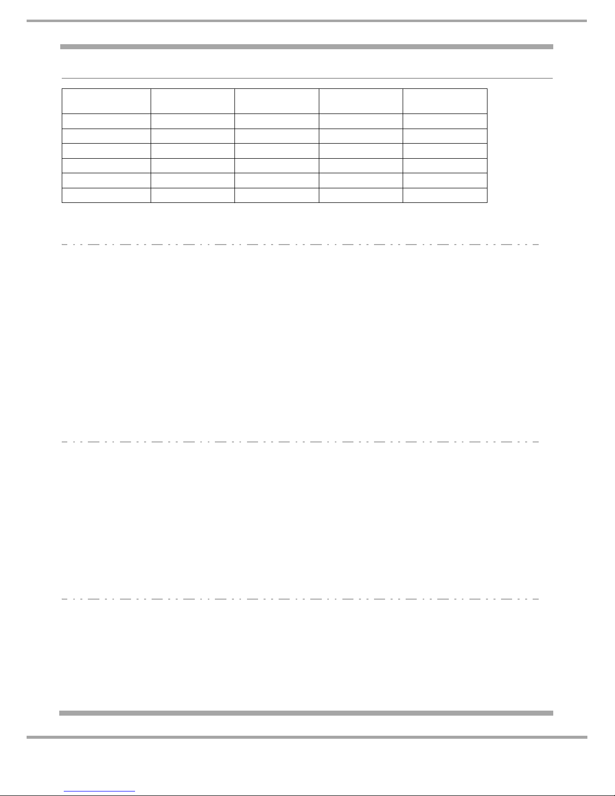
USAGE STATE AND ICON
LITRES TIME (DAYS)
0 - 1350 0 - 250
>1350 >250
>1500 >270
NEW / LOW
USAGE (Green)
MID-HIGH
USAGE (Yellow)
ALARM STAGE
(Red)

13 of 61
Indesit Company
Service Manual UK English
ICE MAKER OPERATION - 2010 DF MODELS
To operate ensure:
• The appliance has reached -9°C for a minimum of 2 hours.
• Crushed ice or cubed ice mode is selected on the user control display.
• The appliance has been on for approximately 12-24 hours at initial start up.
A. Ice Maker Circuit Module. The ice maker has its own circuit module which controls the load, the
heater on the underside of the ice maker and ice maker solenoid valve at the base of the
appliance. (To prevent overfilling the ice maker module will only allow the ice maker solenoid valve
to open up to a maximum of 20 seconds).
B. Emitter and Receiver Sensors. The electronic
control consists of two separate printed circuit
boards mounted on opposite sides of the
freezer liner below the ice maker. The board
mounted on the left hand side of the freezer
liner is referred to as the 'emitter board', and the
board mounted on the right hand side (mullion)
is referred to as the 'receiver board' (Fig. 1).
The electronic control will periodically check to see if the ice
maker is at the home/park position. (Fig. 2 shows the rake in
blue in the home position at the 2 o’clock position). When the
rake is at the home position the relay will de-energize removing
power from the ice maker until the next harvest of ice. When the
ice maker thermostat closes and signals the ice is ready to be
harvested, the emitter board sends out an infrared (IR) pulse.
If the path of the pulse is unobstructed to the receiver board, the phototransistor on the receiver
board will 'sense' the pulse. The control will then energise a relay, which applies power to the ice
maker. A harvest begins.
Closing the freezer door forces the emitter flap to fold
flat to the liner, allowing the IR beam to travel through
the cut out section at the top of the Ice Bucket (Fig. 3).
If ice reaches this point in the bucket, the ice acts as a
barrier to the beam and prevents the IR beam hitting
the receiver sensor on the right. Note: If the door is
open the emitter flap springs open which obstructs the
IR beam travel to the receiver.
The emitter and receiver’s electronic boards control
power to the Ice Maker. These boards can also be
used for the Optics Diagnostic Mode Test
(see Page 38).
The auto test (see Page 34) will not test the ice solenoid valve, the two emitter and receiver
sensors, nor the Ice Maker itself. Refer to Pages 36 - 38 for the Optics Diagnostic Mode Test.
Ice Maker - view from behind cover
Emitter
Receiver
Fig. 1
Fig. 2
Emitter
Ice Maker Cover
Ice
Bucket
Fig. 3

14 of 61
Service Manual UK
Indesit
Company
English
C. Ice Harvesting. The harvesting process begins when the Ice Maker thermostat closes and signals
that the harvest temperature has been reached. The closed thermostat applies power to the ice
maker motor and to the heater. As the heater melts the outer layer of the ice, the motor rotates a
rake (rake in blue in Fig. 2 on previous page), which sweeps the ice cubes out of the mould, and
pushes them forward into the Ice Storage container/ bucket in the freezer door. The harvest lasts
approximately 5 minutes. To prevent an early harvest from occurring after the last harvest is
completed; a minimum of 40 minutes must pass before another harvest will be initiated.
Note: When the water supply is turned off the Ice Mode should be disabled on the user control
display interface.
For Ice Maker Troubleshooting see Page 36.
15 of 61
Indesit Company
Service Manual UK English
ICE MAKER OPERATION - 2011 NDF MODELS
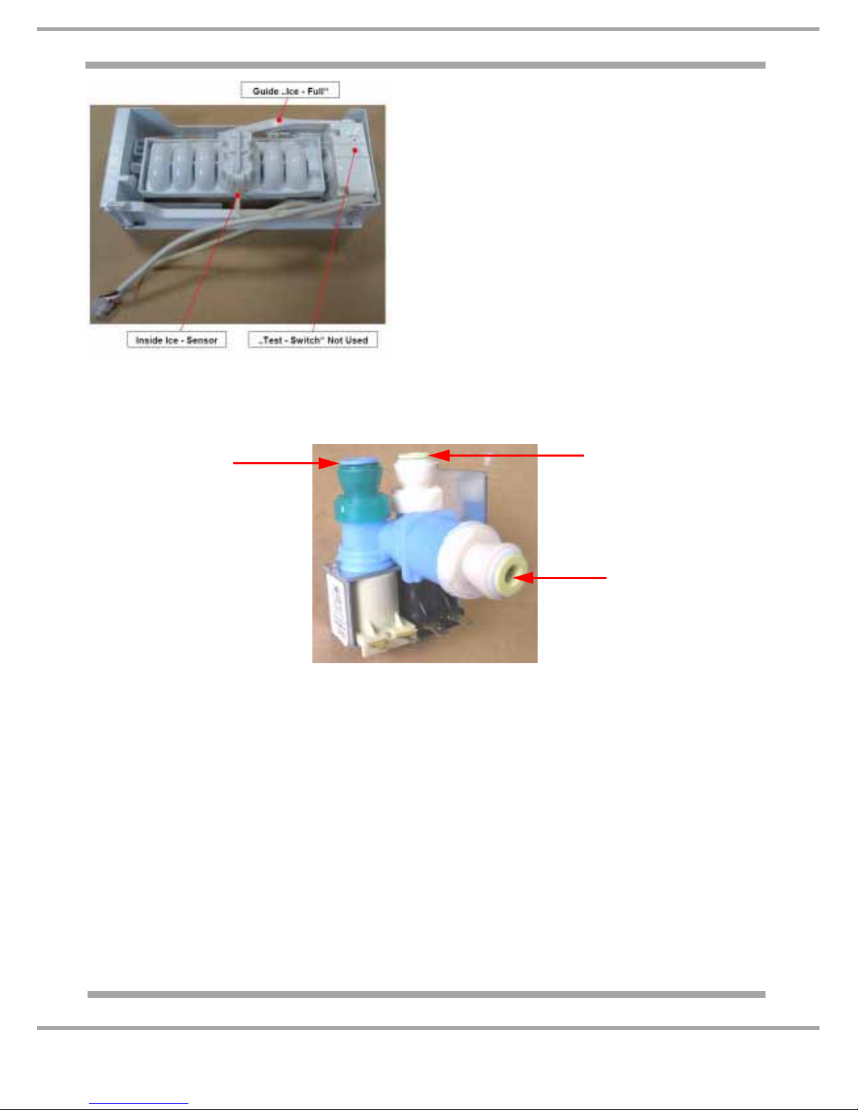
ICE MAKER SANKYO IDI2 (FIG. 4) OPERATION - 2011 NDF MODELS:
To operate ensure:
• The appliance has reached -10°C for a minimum of 2 hours.
• Crushed ice or cubed ice mode is selected on the user
control display.
• The appliance has been on for approximately 12-24 hours at
initial start up. Note: After a period of no use, the icemaker
needs to be run overnight before it will deliver the first cubes.
Ice Maker ON / OFF manager (IDI2 Sankyo):
The Icemaker system is managed by the main power module
determined by ICE mode selected on the user module.
Ice water solenoid activates, this activates the ice fill tube heater
and fills the ice tray with water (See Figs. 5 and 6). Once the
ice-sensor (Fig. 7) signals that the harvest temperature has been
reached, it begins to harvest the ice by twisting the tray (no
heating element inside). The Guide “Ice-Full” arm (Fig. 6) turns
every 2 hours in the down position (30° angle). When the arm
reaches the 30° angle the internal contact inside of the icemaker
gives a signal to the main module. The signal allows ice
production to activate. If the arm cannot go completely down due
to the ice storage container being full (i.e ice is restricting the arm
to lower completely), the feedback signal is therefore missing and ice production is stopped.
Fig. 4
Ice Fill Tube Cover
Guide Ice-full Arm
Ice Maker: side view from the left of freezer
door with ice maker cover removed.
Ice Maker: straight on view of internal freezer
door with ice maker cover removed
Fig. 5
Fig. 6
Fill Tube
& Foil
Heater
Ice Tray
Ice Tray
16 of 61
Indesit Company
Service Manual UK English
To avoid water overflow, the main module will switch
OFF the relay K002 if the ice valve feedback lasts
more than 20 seconds. The Icemaker system will then
be switched OFF until the following points will be
satisfied:
1) The power has been removed (Power-OFF)
2) The main power has been re-applied (Power-UP)
During this failure condition the main power module will
send the alarm code to the User Interface. (See Alarm
Codes on Pages 31 & 32 Ice maker checks can be
done using the Autotest, see Page 34).
Note: When the water supply is turned off the Ice
Mode should be disabled on the user control display
interface.
For Ice Maker Troubleshooting see Page 36
SOLENOID VALVE - SANKYO
WATER SOLENOID VALVE MANAGEMENT:
The water solenoid is activated by the display control board passing the information to the Main board.
The control calculates and recorded the total volume of water flowed through the valve during the
opening periods.
The flow rate is: 1.51 litres per minute (24 – 58 cc per second)
Supply voltage (nominal): 220 V AC; 50Hz
Power dissipation for each coil: 20W
Opening voltage: 190 V; 50Hz (at 862 Kpa, 125 psi)
Water pressure range: 1,38 - 8,27 bar
Flow rate outlet Ice Maker: 65cc / 7.5 sec.
Flow rate outlet water dispenser: 237cc / 7.5 sec.
The diagram on Page 18 shows the water flow system:......
Water Solenoid:
8 mm
Blue collar
Ice Maker Solenoid:
6 mm
Yellow collar
Water inlet from filter
Fig. 8

17 of 61
Indesit Company
Service Manual UK English
ICE SOLENOID WATER VALVE MANAGEMENT (2010 DF MODELS):
The icemaker water solenoid valve will be automatically controlled and driven by the Icemaker.
The flow rate for the icemaker water valve:1.13 litres per minute (140cc per 7.5 seconds +11cc –17cc)
Supply voltage (nominal): 12V
Motor power dissipation: 8 W
Ice production per 24 Hours: Approximately 200 ice cubes
Condition to start ice production: -9°C appliance temperature for min. 2 hours
Condition to stop ice production: -10°C temperature in the mould (ice-sensor)
(The above could vary depending on water pressure, usage of appliance and temperature etc.).
ICE SOLENOID WATER VALVE MANAGEMENT (2011 NDF MODELS)
The icemaker water valve will be automatically controlled and driven by the Main Power Module.
The flow rate for the icemaker water valve: 1.51 litres per minute
Opening time of the icemaker water valve: 5 seconds = ~100cc (+/- 3cc)
Ice valve ALARM indication for opening time: 20 seconds
Water pressure range with filter cartridge: 2.07 bar till 8.27 bar
Water pressure range without water filter: 1.38 bar till 8.27 bar
General Requirements
Supply voltage (nominal): 12V
Motor power dissipation: 8 W
Ice production per 24 Hours: 0.8 kg (six or seven loads)
Condition to start ice production: -10°C appliance temperature for min. 2 hours
Condition to stop ice production: -9°C temperature in the mould (ice-sensor)
Indesit Company
18 of 61
Service Manual UK English
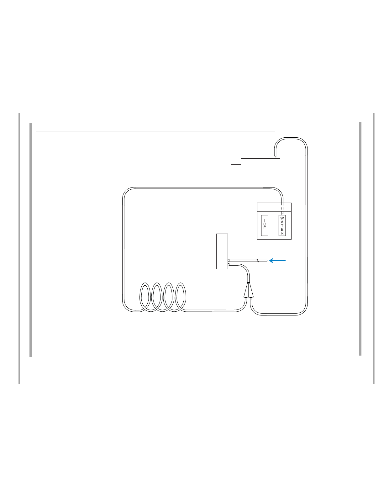
WATER FLOW SYSTEM
Underneath the ice and water dispenser is a grille and sump to catch any spillage that may occur. This is not a drain.
WATER RESERVOIR
LOCATED IN FRIDGE
FILTER
HOUSING
FRONT
REAR
FILL
VALV E
DISPENSER
INTERFACE
ICEMAKER
WATER
INLET
,&(
:$7(5
BLUE/GREEN
YELLOW/WHITE
water flow.ai
19 of 61
Indesit Company
Service Manual UK English
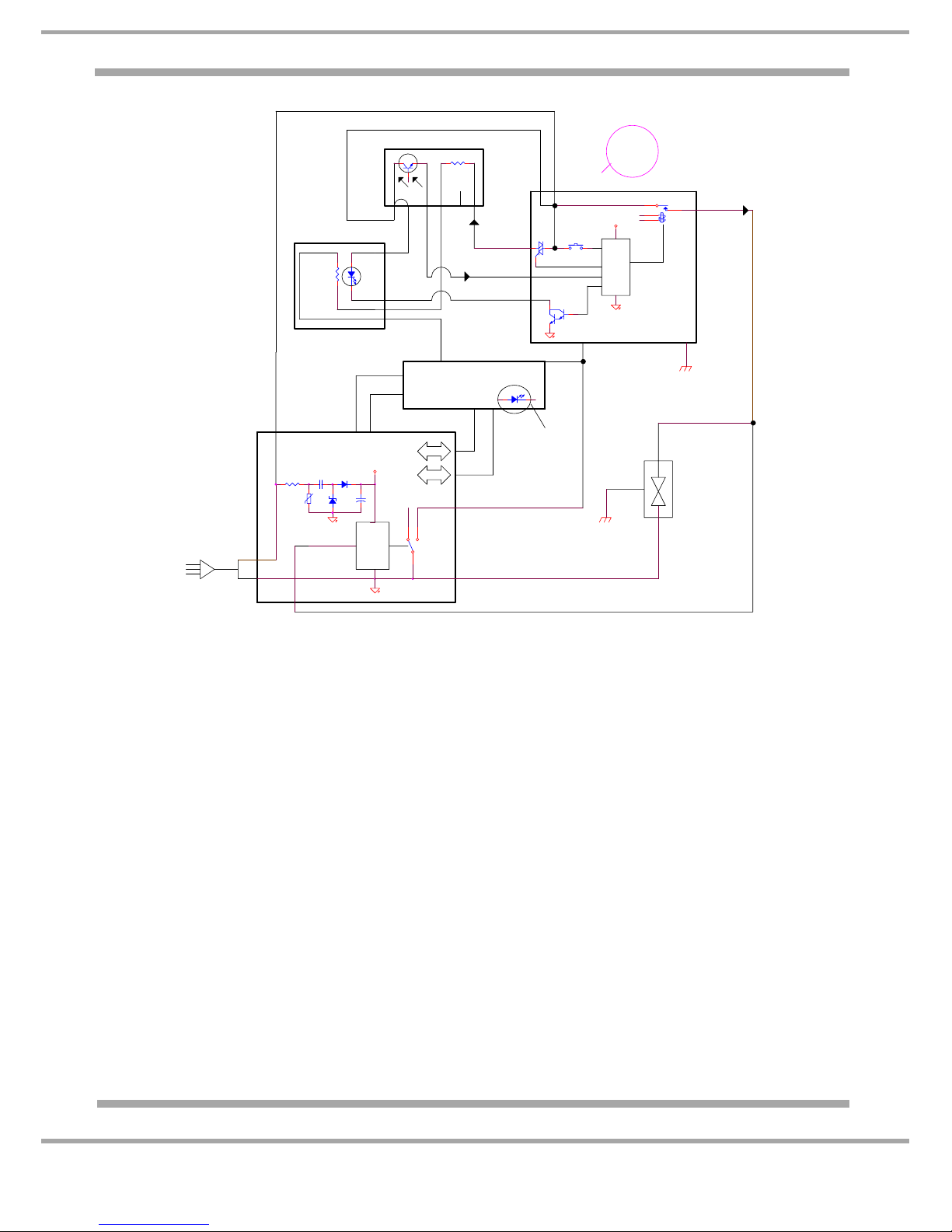
Ice Maker Circuit through the Display, Main Control, Emitter and Receiver Boards
Ice Maker Solenoid Valve Feedback Description
The feed-back circuit mainly gives the information to the microprocessor on how many times the Ice
Maker Valve has been energised. This is recorded by the microprocessor and it is multiplied by the
valve flow rate in order to record how many litres of water flows through the valve and consequently
through the filter.
So, the Water Filter Indicator can be updated accordingly. The feed-back is also used by the Main
Board in order to understand if the Ice Maker is stuck at water fill position and to avoid water overflow.
The following describes how the feed-back works: If the Ice Maker Valve command lasts more than 20
seconds the Ice-Maker equipment will be switched OFF until the following points are satisfied in the
following sequence:
1) Press the reset button (alarm and buzzer OFF/Ice-Maker OFF).
- When the alarm is enabled the buzzer will sound and the Ice Mode LEDs will blink alternately.
2) Unplug the appliance from the electricity supply.
3) Plug the appliance back into the electricity supply.
Note:
a) If the user tries to switch ON the Ice-Maker before executing point 2, the alarm will re-start again
and the relay will remain in the OFF state.
b) If after point 3) the situation persists and the above alarm will restart., further diagnosis will be
required. Refer to Page 36.
+5VDC
+5VDC
+
321
4
3
1
2
User Interface
N
Main plug
220Vac
N
Main Board
TX
RX
Feed-back
Ice valve
Water Filter
Indicator
L
L
Neutral
Line
uP
Relè
Ice-Maker
Line
Neutral
Ice
Valve
(black)
(IR_Emitter)
3
Short
(Line/Phase)
Pole 3 of 10
Line21
Heater
De-Frost
Ice-Maker
Neutral
Emitter
4
(Neutral)
Receiver
(Line/De-Frost)
3
Pole 1 and 9 not connected
(IR_Line)
Pole 5 of 10
2
5
6
(IR_Receiver)
Pole 4 of 10
(Physical GND)
Heater De-Frost
Pole 2 of 10
(Water_valve)
4
Line
This is Pole
1 of 10 for
NAR 120V
version
n.c.
Pole 8 of 10
Pole 10 of 10
Pole 7 of 10
uP
1
Bimetal
Pole 6 of 10
DF 2010 Models
 Loading...