

Hotpoint MSZ802DF, MSZ806DF, MSZ803DF, MSZ801DF Service Information

Indesit Company UK Ltd
© 2011 Reg. Office: Peterborough PE2 9JB Registered in London: 106725
Service
Information
HOTPOINT
SIDE-BY-SIDE
FRIDGE
FREEZERS
(7 ~ Segment Version)
Models Comm.
Covered Code
Energy Band 'A' Models
MSZ801DF 48862
MSZ802DF 46196
MSZ803DF 48863
MSZ806DF 57217
5407399 Issue 2 March 2011

2 of 37
Service Manual UK
Indesit
Company
English
HEALTH AND SAFETY
For the servicing of refrigeration products, containing R134a refrigerant.
These instructions are in addition to any other Company procedures already published.
Published primarily for Indesit Company engineers working in the UK or Southern Ireland, for
which these instructions are MANDATORY.
General
1. This manual is not intended as a comprehensive repair/maintenance guide to the appliance.
2. It should only be used by suitably qualified persons having technical competence, applicable product
knowledge, suitable tools and test equipment.
3. Servicing of electrical appliances must be undertaken with the appliance disconnected. (unplugged
from the electrical supply).
4. Servicing must be preceded by earth continuity and insulation checks.
5. Personal safety precautions must be taken to protect against accidents caused by sharp edges on
metal and plastic parts.
6. After servicing, the appliance must be rechecked for electrical safety.
Refrigerant R134a - Safe Handling - Transporting & Storage
1. Work areas should be well ventilated and any immediate heat sources turned off.
2. Do not smoke where there is a possibility of refrigerant in the atmosphere. Customer/s should also
be advised.
3. Cylinders must not have heat applied, or stand close to a heat source, and should be stored out of
direct sunlight.
4. Should a sudden release of refrigerant occur, open windows or outside doors in the immediate
vicinity, then evacuate for a few minutes.
5. It is illegal to intentionally vent R134a refrigerant to atmosphere. Follow the company procedure on
collection and reclamation.
6. If a leak is identified the appliance must be repaired immediately if possible.
7. Where it is not possible to repair the appliance immediately the customer should be advised:
Appliance should be turned off and the refrigerant recovered.
8. Returned compressors must be sealed to prevent the escape of oil and refrigerant. Refer to the
Environmental responsibilities for service engineers in your Health and Safety booklet.
9. Cylinders (R134a) being transported must be in an upright position on the floor of the vehicle and
prevented from movement.
10. A green compressed gas label Part No. 8100062 should be displayed on the rear of the vehicle.
3 of 37
Indesit Company
Service Manual UK English
CONTENTS
Health & Safety . . . . . . . . . . . . . . . . . . . . . . . . . . . . . . . . . . . . . . . . . . . . . . . . . . . . . . . 2
Index & Serial Number / Product Identity . . . . . . . . . . . . . . . . . . . . . . . . . . . . . . . . . . 3
Introduction . . . . . . . . . . . . . . . . . . . . . . . . . . . . . . . . . . . . . . . . . . . . . . . . . . . . . . . . . . 4
Specifications . . . . . . . . . . . . . . . . . . . . . . . . . . . . . . . . . . . . . . . . . . . . . . . . . . . . . 5 - 6
Appliance Dimensions & Water Filter . . . . . . . . . . . . . . . . . . . . . . . . . . . . . . . . . . . . . 7
Detailed View . . . . . . . . . . . . . . . . . . . . . . . . . . . . . . . . . . . . . . . . . . . . . . . . . . . . . . . . . 8
Control Panel Interface . . . . . . . . . . . . . . . . . . . . . . . . . . . . . . . . . . . . . . . . . . . . . 9 - 10
Description of Functions . . . . . . . . . . . . . . . . . . . . . . . . . . . . . . . . . . . . . . . . . . . . . . 11
Component Functions . . . . . . . . . . . . . . . . . . . . . . . . . . . . . . . . . . . . . . . . . . . . 12 - 13
Temperature Tables . . . . . . . . . . . . . . . . . . . . . . . . . . . . . . . . . . . . . . . . . . . . . . . . . . 14
Alarm Conditions . . . . . . . . . . . . . . . . . . . . . . . . . . . . . . . . . . . . . . . . . . . . . . . . . . . . 15
Auto-Test and Fault Conditions. . . . . . . . . . . . . . . . . . . . . . . . . . . . . . . . . . . . . 16 - 17
Air Flow . . . . . . . . . . . . . . . . . . . . . . . . . . . . . . . . . . . . . . . . . . . . . . . . . . . . . . . . 18 - 19
Ice-Maker Function and Adjustment . . . . . . . . . . . . . . . . . . . . . . . . . . . . . . . . . . . . . 20
Power Module Parameters . . . . . . . . . . . . . . . . . . . . . . . . . . . . . . . . . . . . . . . . . 21 - 22
Servicing & Dismantling Instructions . . . . . . . . . . . . . . . . . . . . . . . . . . . . . . . . 23 - 26
Compressor Connection Chart . . . . . . . . . . . . . . . . . . . . . . . . . . . . . . . . . . . . . . . . . 27
Power Module Edge Connections . . . . . . . . . . . . . . . . . . . . . . . . . . . . . . . . . . . . . . . 28
Connector Block Chart . . . . . . . . . . . . . . . . . . . . . . . . . . . . . . . . . . . . . . . . . . . . . . . . 29
Theoretical Wiring Diagram . . . . . . . . . . . . . . . . . . . . . . . . . . . . . . . . . . . . . . . . . . . . 30
Thermistor Sensor Location . . . . . . . . . . . . . . . . . . . . . . . . . . . . . . . . . . . . . . . . . . . 31
Installation Instructions . . . . . . . . . . . . . . . . . . . . . . . . . . . . . . . . . . . . . . . . . . . 32 - 36
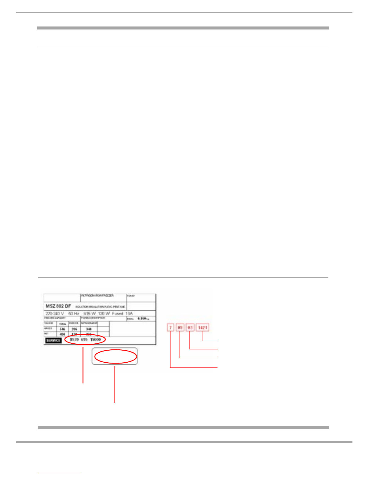
PRODUCT IDENTITY
Example
705031421
1 Industrial Code: 8539 695 15000
2 Serial Number:
Printed on a separate label below the Rating Plate
Build number that day, e.g. 1421th built
Day of manufacture, e.g. 03
rd
of month
Month of manufacture, e.g. May
Year of manufacture, e.g. 2007
1
2

4 of 37
Service Manual UK
Indesit
Company
English
MODEL INTRODUCTION
The models included in this publication are 1765 mm high Side by Side no-frost Fridge Freezers that
were introduced in July 2007. All models are similar with regard to the furniture design, but there are
variations for exterior colour.
Models MSZ801DF, MSZ802DF, MSZ803DF and MSZ806DF interior:
The interior of the fridge has safety glass shelves, one meat drawer (chiller) and one humidity
controlled salad bin (crisper) with a glass cover. The door has two deep shelf, dairy shelf with a lid, a
commodity shelf and lower bottle shelf.
The interior of the freezer section has two drawers of varying sizes, two safety glass shelves of varying
sizes and ice cube maker. The door has four commodity shelves of varying sizes.
For banding and colour information, refer to the Front Cover and or Specifications page.
The appliance is “no-frost” design so defrosting is automatic.
All models have wheels at the rear and wheels / adjustable feet at the front.
The digital display interface module (7 ~ segment LED) is mounted in the front of the freezer door with
the drinks dispenser, the fast freeze button and ice maker controls are also mounted in the same area.
The fridge and freezer temperature settings are adjusted by selecting the + / - buttons next to the
relevant temperature display window. All functions are monitored and actioned by the power module
mounted at the rear of the appliance within the compressor compartment.
The climate class is N / ST signifying that it is designed to operate in ambient temperatures between
+16°C to +38°C.
As with many refrigeration appliances, it is important that it is installed and operated within the
recommended ambient temperature range and that there is adequate ventilation.
All appliances equipped with an automatic ice-maker and water dispenser must be connected to a
water supply that only delivers drinking water. See specification page for pressure requirements.
5 of 37
Indesit Company
Service Manual UK English
SPECIFICATIONS
GENERAL:
Manufactured in: Italy
Appliance Type: Side by Side
Static / No- Frost: No-Frost
Door Hinging - Freezer L/H & Fridge R/H
Reversible: No
Plug/Cable: UK / 1.6m
Water Pipe: 1.65m
Noise Level: 'A' band models ~ 45dB
Climate Class: (Rating Plate) N.ST = 16°C to 38°C
Refrigeration Type: No-Frost - Fin On Tube (FOT)
DIMENSIONS & WEIGHT:
Height: 1774 mm
Width: 902 mm
Depth: 752 mm
To allow product handling and sufficient air circulation, leave at least 10 mm clearance at the sides,
above the appliance and between the rear panel and the wall.
Weight Gross: 146 kg
Weight Net: 140 kg
CAPACITIES / VOLUME:
Gross Volume Net Volume
Fridge: 340 litre 335 litre
Freezer: 206 litre 155 litre
Freezing Capacities 24 hrs 12 kg
Conservation Time 5 hours
Introduction Date
Colours June 2007 July 2007 July 2008
Polar White
MSZ801DF
Silver MSZ802DF
Stainless Steel MSZ803DF
Black MSZ806DF
Suffix 'DF' = dispenser models

6 of 37
Service Manual UK
Indesit
Company
English
TECHNICAL DATA:
Power Supply Voltage: 220/240 V
Power Supply Frequency: 50 Hz
Mains Water Supply: Min. 1.7 bar
Max. 8.1 bar
Freezer Lamp: E27 40W 220V - 240V
Dispenser Lamp: E14 10W 230 - 240V
Fridge Lamp (Blue Light): T-Click 40W 220V - 240V
ENERGY
Energy Class: A
Power Consumption: 1.39 kWh/24hr
Annual Consumption: 507.3 kWh/yr
COMPRESSOR WINDING
Manufacturer: Embraco
Type I/D: EGYS 90 HLP
Winding Resistance
Start: 21.3 :
Run: 12.3 :
Refrigerant/ Grams: R134a / 160g - Refer to the appliance rating plate
Insulation: C-Pentane
HEATER RESISTANCES
Evaporator Defrost Heater: 8.57 k:
COMPONENT RESISTANCES
Condenser Fan Motor: 4.49k:
Evaporator Fan Motor: 2.35k:
Water Dispenser Solenoid Valve: 8.68k:
Water Ice Maker Solenoid Valve: 8.71k:
7 of 37
Indesit Company
Service Manual UK English
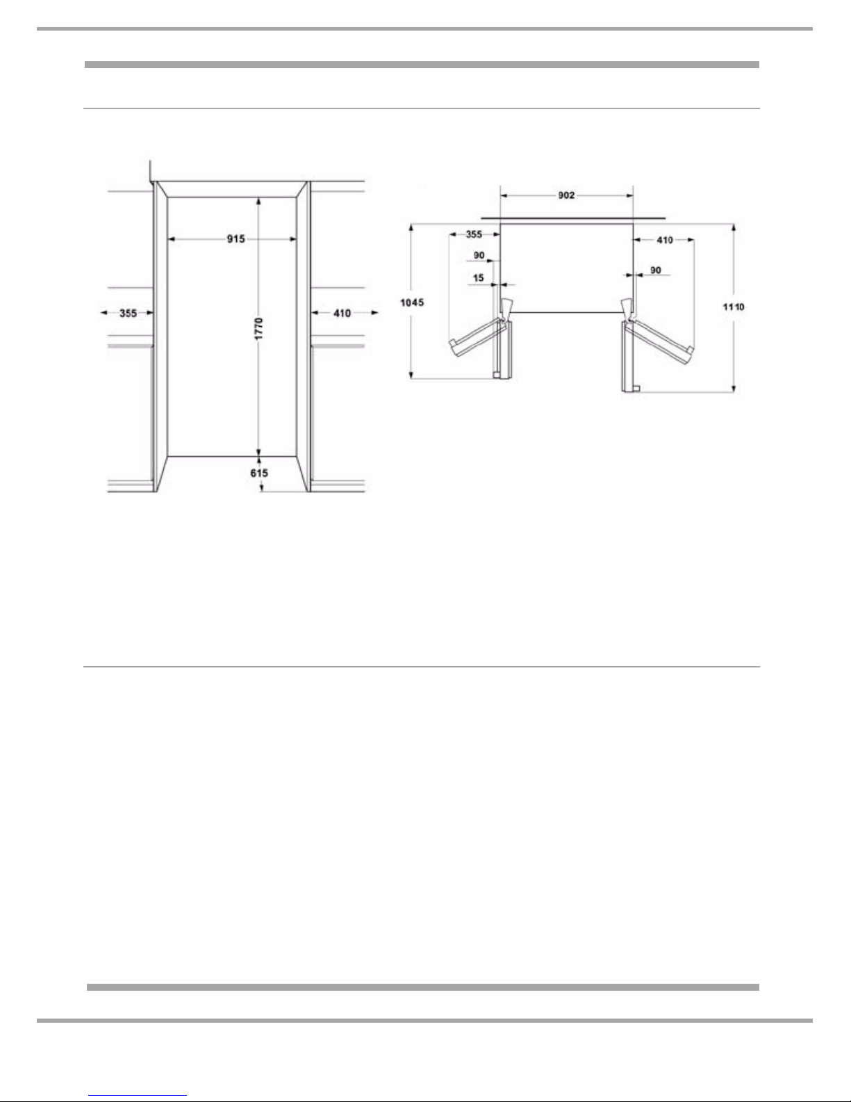
APPLIANCE DIMENSIONS (all measurements are approximate)
WATER FILTER
1. Locate the water filter cartridge cap below the freezer compartment door.
Rotate the cap counter clockwise to a vertical position and pull the cap and filter cartridge out
through the base grille. Note: Since there is water in the cartridge, some spilling may occur.
2. Remove the cartridge cap by sliding it off the end of the old cartridge.
DO NOT DISCARD THE CAP.
3. Take the new cartridge out of its packaging and remove the protective cover from the o-rings.
Make a note of the installation date in the space provided on the new cartridge.
4. Slide the cartridge cap onto the new cartridge.
5. With the cartridge cap in the vertical position, push the new filter cartridge into the base grille until
it stops. Rotate the cartridge cap clockwise to a horizontal position.
6. RUN WATER THROUGH THE DISPENSER UNTIL THE WATER RUNS CLEAR (about 9-14 litres
or 6-7 minutes). This will clean the system and clear air from the lines. Note: As air is cleared from
the system, water may spurt out of the dispenser.
APERTURE MEASUREMENTS PLAN VIEW
(WITH DOORS OPEN 90° AND FULLY)
Cabinet Height = 1760 mm
Cabinet Height with doors = 1765 mm
Depth including door handles: 605 mm + 150 mm = 750 mm
Depth without doors = 605 mm
Depth without handles: 605 mm + 110 mm = 715 mm
8 of 37
Service Manual UK
Indesit
Company
English
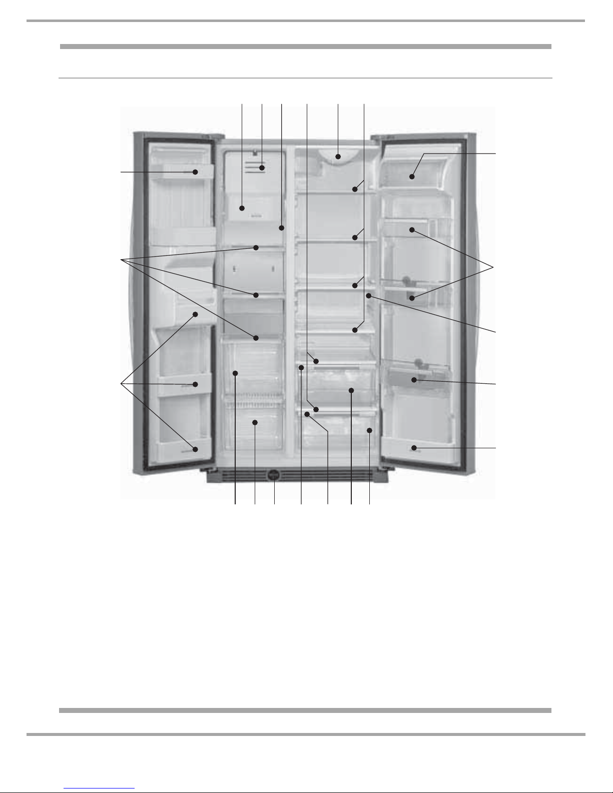
DETAILED VIEW
REFRIGERATOR COMPARTMENT
A. Inside light
B*. Inside light (not tted)
C. Adjustable shelf
D. Shelf - drawer lid
E Crisper (Salad Bin)
F. Crisper adjustment (Humidity Control)
G. Meat / vegetable drawer (Chiller)
H. Meat / vegetable drawer adjustment
I. Dairy products compartment
J. Door trays
K. 2-litre door tray with bottle holder
L. 0.75 litre door tray
M. Water lter
FREEZER COMPARTMENT
N. Automatic ice-maker
O. Glass shelves / Racks (depending on the model)
P. Drawer / Bottom basket (depending on the model)
Q. Drawer / Top basket (depending on the model)
R. Ice cube drawer
S. Freezer door trays
T. Inside light
ADNR C
B
I
K
L
J
FEHGFMPQ
O
S
S
T
*
9 of 37
Indesit Company
Service Manual UK English
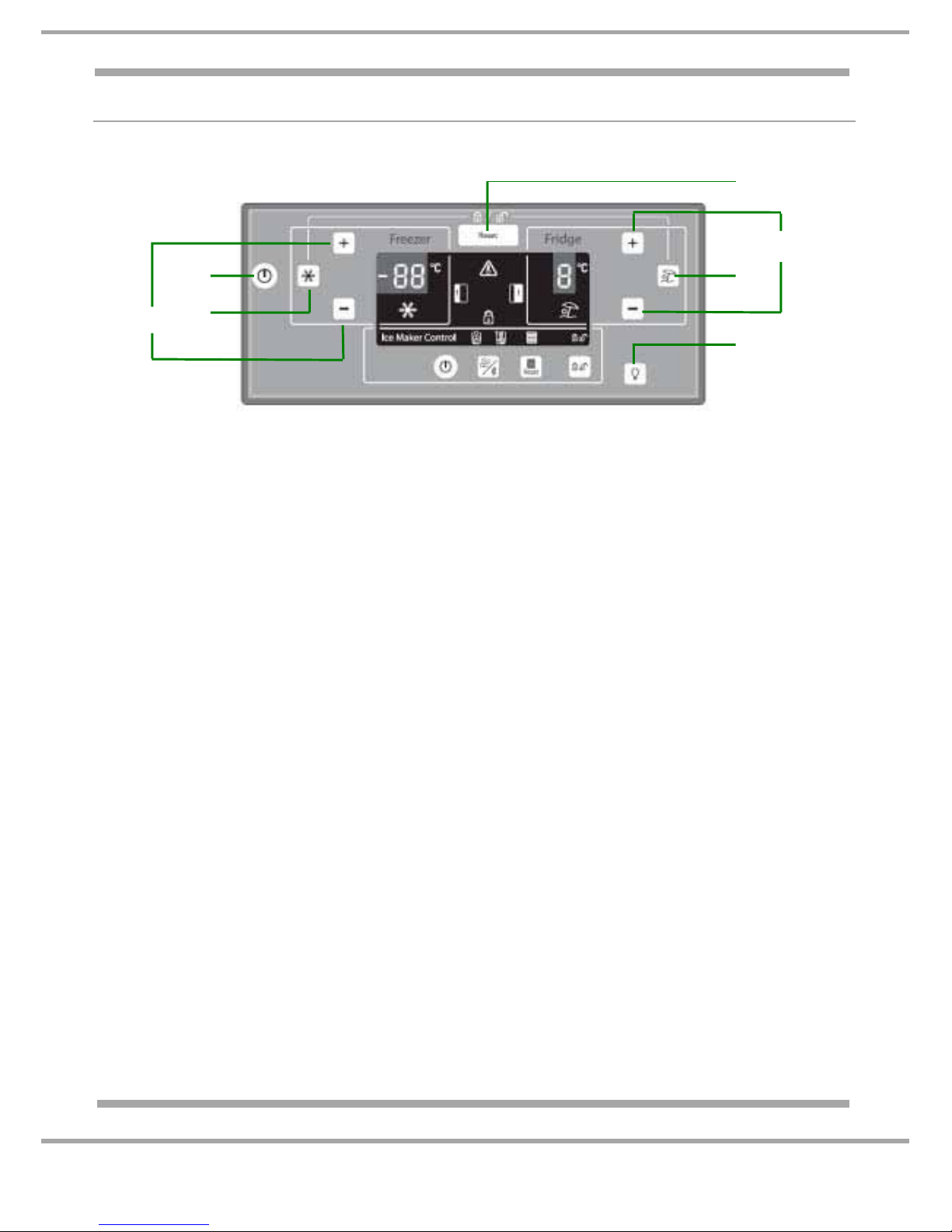
CONTROL PANEL INTERFACE
TEMPERATURE CONTROL PANEL
BUTTON DESCRIPTION FUNCTION
A Freezer
temperature
adjust / select
~ This function allows you to adjust the displayed temperature.
To adjust the temperature press the relevant + / - button until the
required freezer temperature is displayed on the left.
B Super freeze ~ This function activates the super freeze (fast freeze) so fresh
food can be frozen. To enable press until the super freeze
symbol appears on the Display. It will automatically disable after
48 hours or when the button is pressed again.
C Stand-by function ~ This function turns off the refrigerator and freezer compartments
to enable press and hold for 3 seconds: the display will go out
and a dash will appear on the left display.
To disable press and hold for 3 seconds: the display will return to
the previous set temperatures.
D Reset ~ This function can be used in the event of an alarm when an
acoustic signal and relevant indicator lights are activated.
To disable the acoustic alarm signal press the reset button.
E Fridge
temperature
adjust / select
~ This function allows you to adjust the displayed temperature.
To adjust the temperature press the relevant + / - button until the
required fridge temperature is displayed on the right.
F Holiday function ~ This function allows the fridge compartment to be deactivated if
the user is going away for sometime, the fridge will maintain
adequate temperature for preventing the formation of odours,
therefore not necessary to switch the appliance off.
B+F Control panel
Lock function
(Child lock)
~ This function locks the fridge and freezer controls.
To lock press and hold both the super freeze and super cool
buttons simultaneously for 3 seconds until the lock symbol
appears in the display and is accompanied by an acoustic signal.
C
D
E
F
G
A
B
10 of 37
Service Manual UK
Indesit
Company
English
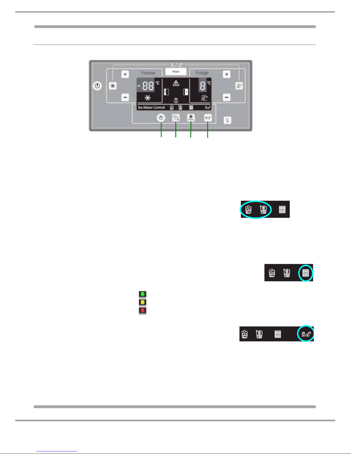
CONTROL PANEL INTERFACE
ICE & DISPENSER CONTROL PANEL
BUTTON DESCRIPTION FUNCTION
G Dispenser light ~
This function switches on the dispenser light. To enable / disable
press the button.
H Stand-by function ~ This function turns off the ice maker.
To enable the ice maker press and
hold until the ice or crushed ice
symbol is displayed.
To disable the ice maker press and
hold until the ice or crushed ice symbol is extinguished.
J Ice mode function ~ This function allows you to select between ice cubes or crushed
ice to be dispensed.
K Reset ~ This function resets the water filter
replacement time.
Normally the water filter symbol is Green
(Blue on some models).
= Water Filter OK (Blue on some models)
= Water Filter requires replacing soon.
= Water Filter needs replacing.
L Ice maker lock ~ This function locks the ice maker
and water dispenser controls.
To lock press and hold for 3
seconds until the lock symbol
appears in the display and is
accompanied by an acoustic signal.
To unlock press and hold for 3 seconds until the symbol is
extinguished.
LKJH

11 of 37
Indesit Company
Service Manual UK English
DESCRIPTION OF FUNCTIONS
Super freeze function ~ This enables and controls the compressor, condenser fan and evaporator
fan to cool down the freezer compartment independently of the temperature
settings set by the user. The super freeze function will end automatically
after 48 hours after activation.
Freezer Temperature ~ This can be adjusted and selected by the “+ / -“ buttons in the freezer
section of the control interface. For each press of the relevant button you
will increase / decrease the temperature setting by 1°C increments.
The range is from -18°C (-17°C some models) to -24°C.
Freezer Door Alarm ~ The door alarm symbol lights up and the acoustic alarm is activated when
the freezer door remains open. When the door is left open for more than
2 minutes, the symbol flashes and an acoustic signal sounds.
Fridge Door Alarm ~ The door alarm symbol lights up and the acoustic alarm is activated when
the fridge door remains open. When the door is left open for more than
2 minutes, the symbol flashes and an acoustic signal sounds.
Fridge Temperature ~ This can be adjusted and selected by the “+ / -“ buttons in the fridge
section of the control interface. For each press of the relevant button you
will increase / decrease the temperature setting by 1°C increments.
The range is from +2°C to +6°C.
Holiday Function ~ This enables and controls the fridge damper (baffle) and evaporator fan
for the holiday mode. The evaporator fan is activated and the fridge
damper (baffle) is opened for only 2 minutes. This process is repeated
every 30 minutes while the holiday function is enabled.

12 of 37
Service Manual UK
Indesit
Company
English
COMPONENT FUNCTIONS
General Information
The power module is made up of a number of smaller individual modules (sections), each one
controlling a functional component. The modules are linked together when required to control a
particular function or functions. The linking of the individual modules is optional and therefore allows for
each module to be switched ON or OFF, this is determined from the data stored or collected by the
modules and the results of module comparisons.
The power module memory stores information such as temperatures and times.
Having individual set of parameter values built in to it, directly aimed at providing the specific control
needs for the physical and system characteristics of the model type.
Fridge & Freezer Control
The power module monitors the fridge and freezer air sensors, comparing their sensor resistance
values with the cut-in and cut-out parameter values stored in its memory.
Although the parameters are set, they allow for adjustment within those parameters so that the user
has control. The results from the comparisons will determine if cooling is initiated, other circuits of the
module will also use the results.
The power module will enable normal operation provided there is no malfunction condition.
Fridge or Freezer Malfunction Module
The fridge or freezer malfunction module enables the appliance to continue operating in the unlikely
hood of the fridge or freezer sensors failing. Pre-set timed functions stored in the modules memory is
used to cycle cold request on and off.
A malfunction occurs when the fridge or freezer cabinet sensors return a value to the module of either
Open or Closed circuit, rather than a particular resistance value.
Evaporator Fan Module
The freezer fan is located above the evaporator coil and is designed to distribute the cold air produced
by the evaporator coil uniformly inside the freezer compartment and when necessary in the fridge
compartment.
The freezer fan is managed by the module and is switched on/off after a preset time interval that is
parameterised in the modules memory after a compressor start/stop.
The fan will not operate when in the defrost cycle.
After the defrost cycle the fan starts after a timed interval following a compressor start, this interval is
also parameterised in the modules memory; this interval is different from the interval programmed for
normal operating conditions.
Electronic Motorised Damper Assembly (Baffle)
The purpose of the damper is to allow the cold air produced by the evaporator to be distributed inside
the refrigerator compartment.
The damper is located in the top left hand (SX) corner of the fridge compartment. It is controlled by a
fridge air sensor (thermistor) positioned in the centre of the rear wall of the fridge. Cold air from the
evaporator is distributed in the refrigerator compartment.
continued.....
 Loading...