

Hot Point HTDP120ED User Manual
HTDP120ED
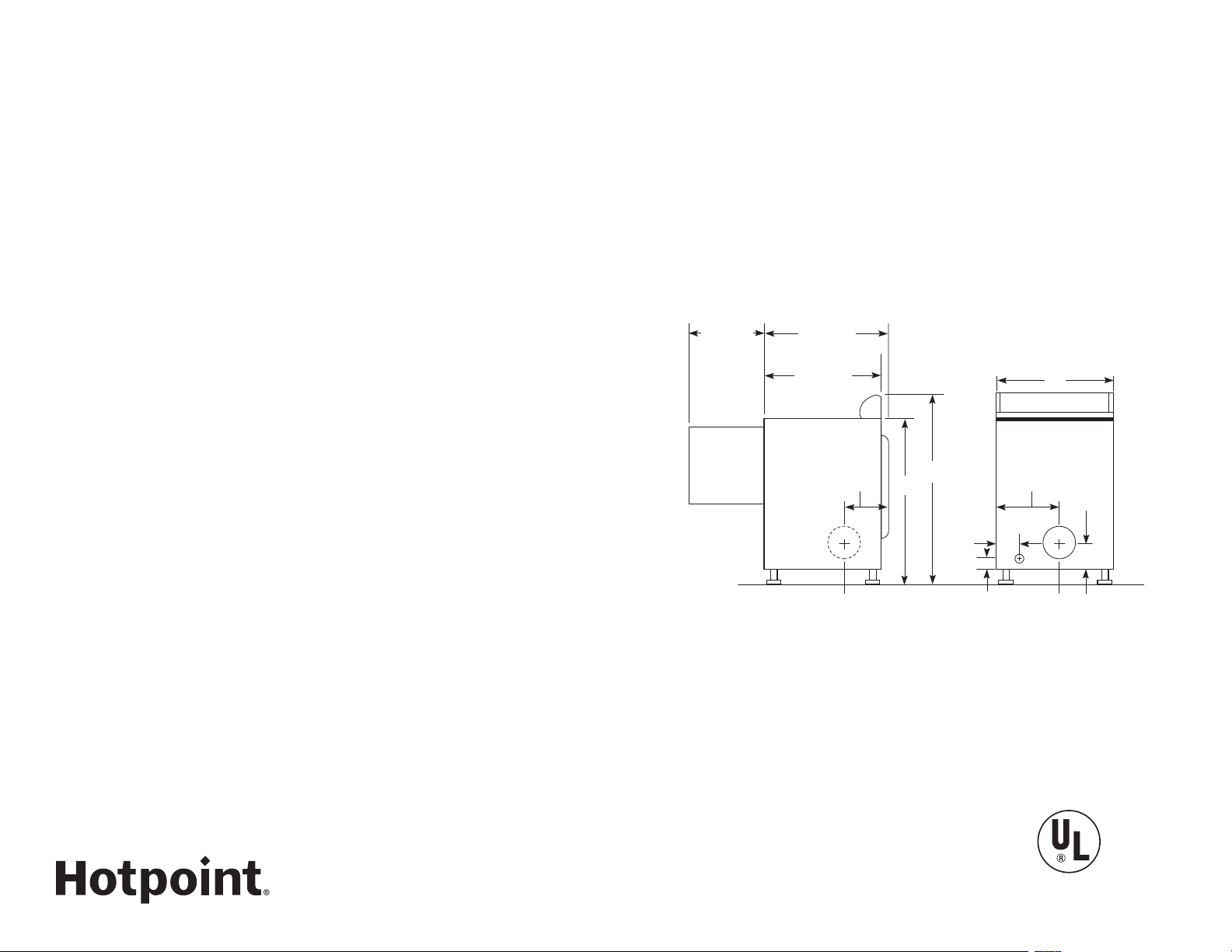
36
28-1/4
42
54-1/2
SIDE VIEW
27
REAR VIEW
36
42
27
2
3-1/2
2-1/2
25-1/2*
SIDE VIEW
REAR VIEW
8-1/2
28-1/4
23-1/2
11-3/4
*24-1/2" from the edge of the side panel to the front.
25-1/2" from the front edge of endcaps.
Hotpoint® 6.8 Cu. Ft. Capacity DuraDrum Electric Dryer
DimEnsiOns anD installatiOn infOrmatiOn (in inChEs)
Exhaust OptiOns: 4-way via rear, right, left and bottom.
CirCuit rEquirEmEnts: An individual, properly-grounded branch circuit,
protected by a 30-amp circuit breaker or a time-delay fuse, is required.
ElECtriC DryEr rating:
240V, 5600W, 60Hz, 24 Amp, 208V, 4400W, 60Hz, 22 Amp
install atiOn infO r matiOn: For complete information, see installation
instructions packed with product for current dimensional data. Special Installation
Requirements
alCOvE Or ClOsEt installatiOn:
- If your dryer is approved for installation in an alcove or closet, it will be stated on
a label on the dryer back.
- The dryer MUST be exhausted to the outside.
- Minimum clearances between dryer cabinet and adjacent walls or other surfaces are:
0" either side, 3" front and rear
- Minimum vertical space from floor to overhead cabinets, ceilings, etc. is 52".
- Closet doors must be louvered or otherwise ventilated and must contain a
minimum of 60 sq. in. of open area equally distributed. If this closet contains both
a washer and a dryer, doors must contain a minimum of 120 sq. in. of open area
equally distributed.
- No other fuel-burning appliance shall be installed in the same closet with a gas dryer.
BathrOOm Or BEDrOOm installatiOn:
- The dryer MUST be exhausted to the outdoors.
- The installation must conform with the local codes, or in the absence of local
codes, with the National Electric Code and National Fuel Gas Code, ANSI Z223
for gas dryers.
minimum ClEaranCEs OthEr than alCOvE Or ClOsEt
install atiOn:
- Minimum clearances to combustible surfaces
0" both sides, 3" rear
Listed by
Underwriters
Laboratories
Specification Created 11/15
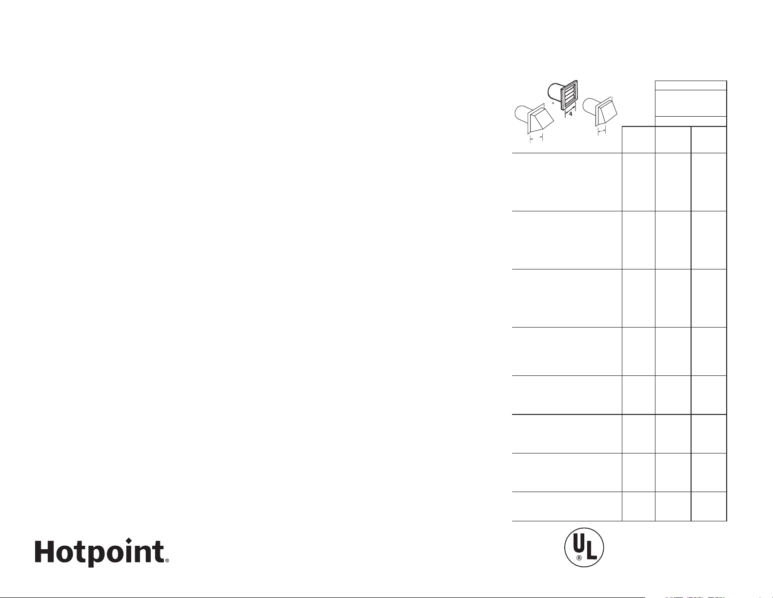
A
B
4
GE Dryer Vent
B
2-1/2
HTDP120ED
Hotpoint® 6.8 Cu. Ft. Capacity DuraDrum Electric Dryer
fOr COmplEtE infOrmatiOn, sEE installatiOn instruCtiOns
paCkED with yOur DryEr.
DuCting matErials:
For best performance, this dryer should be vented with 4" diameter all rigid metal
exhaust duct. If rigid metal duct cannot be used, then UL-listed flexible metal
(semi-rigid) ducting can be used (Kit WX08X10077). In special installations, it
may be necessary to connect the dryer to the house vent using a f lexible metal
(foil-type) duct. A UL-listed flexible metal (foil-type) duct may be used ONLY in
installations where rigid metal or f lexible metal (semi-rigid) ducting cannot be
used AND where a 4" diameter can be maintained throughout the entire length of
the transition duct. Please see installation instruction packed with your dryer for
complete instructions when using flexible metal (foil type) ducting.
Exhaust lEngth CalCulatiOn:
1. Determine the number of 90° turns needed for your installation. If you exhaust
to the side or bottom of dryer, add one turn.
2. The maximum length of 4' rigid (aluminum or galvanized) duct which can be
tolerated is shown in the table.
A turn of 45° or less may be ignored. Two 45° turns within the duct length should
be treated as a 90° elbow. A turn over 45° should be treated as a 90° elbow.
Dryers must be exhausted to the outside.
CautiOn: For personal safety do not terminate exhaust into a chimney, under
any enclosed house f loor (crawl space), or into an attic, since the accumulated
lint could create a fire hazard or moisture could cause damage. Never terminate
the exhaust into a common duct or plenum with a kitchen exhaust, since the
combination of lint and grease could create a fire hazard.
Exhaust ducts should be terminated in a dampered wall cap to prevent back
drafts, bird nesting, etc. The wall cap must also be located at least 12" above the
ground or any other obstruction with the opening pointed down.
For every extra 90° elbow, reduce the allowable vent system length by 10 ft.
Two 45° elbows will be treated like one 90° elbow.
For the side exhaust installations, add one 90° elbow to the chart.
The total vent system length includes all the straight portions and elbows of
the system (transition duct included).
DryEr Exhausting infOrmatiOn—
usE mEtal DuCt Only vErtiCal anD
hOrizOntal DuCting
BEST PERFORMANCE
Maximum length
A
Number
of 90°
Domestic dryer models
GE Front Load Long Vent 7.0
cu. ft. capacity electric dryer
(GF DL)
Long Vent 6.0 - 8.0 cu. ft.
capacity electric & gas dryers
(GTDL and GT V)
Long Vent 7.0 cu. ft. capacity
electric & gas (GTD42, GTD45 ,
GTD65 , GTX42 and GTX60)
All 6.0 - 8 .3 cu. ft. capacity
models electric and gas dryers
(GFDS, GFDR, GFDN, GTDS,
GTDN, GHDN, GHDS, GTD P,
GLDP, GTD, HTDP, HTDX)
DCVH480
All 3.6 cu. ft. (DSKS , DSKP)
electric dryers
Laundry Center GUD27
Laundry Center GUD24
Listed by
Underwriters
Laboratories
of 4" dia rigid
metal duct
Exhaust hood type
A
4"
turns
opening
0 200 ft. 175 ft.
1 185 f t. 165 ft.
2 175 ft. 155 ft.
3 165 ft. 145 ft.
4 155 ft. 135 ft.
5 145 ft. 125 ft.
0 150 ft. 125 ft.
1 135 ft. 115 ft.
2 125 ft. 105 ft.
3 115 f t. 95 ft.
4 105 ft. 85 ft.
5 95 f t. 75 ft.
0 120 ft. 90 ft.
1 100 ft. 75 ft.
2 85 f t. 65 ft.
3 70 ft. 55 ft.
4 60 ft. 45 ft.
5 55 f t. 35 ft.
0 90 ft. 60 ft.
1 60 ft. 45 ft.
2 45 ft. 35 ft.
3 35 f t. 25 ft.
4 25 ft. 15 ft.
0 90 ft. 60 ft.
1 60 ft. 45 ft.
2 45 ft. 35 ft.
3 35 f t. 25 ft.
0 46 ft. 37 ft.
1 37 ft. 30 ft.
2 30 ft. 22 ft.
3 23 f t. 15 ft.
0 56 ft. 42 ft.
1 48 ft. 34 ft.
2 40 ft. 26 ft.
3 32 f t. 18 ft.
0 43 ft. 36 f t.
1 33 ft. 26 f t.
2 24 f t. 16 ft.
Specification Created 11/15
B
2-1/2"
opening
 Loading...