

Hotpoint ADW1100N00BB, ADW1100N00WW, ADW1100N10BB, ADW1100N10WW, ADW1100N15BB Installation Guide
...
Appliances
Installation Instructions
Built-In Dishwasher
If you have questions, call 800.GE.CARES1800.432.2737} or visit our website at: www.ge.com
BEFORE YOU BEGIN
Read these instructions completely and
carefullg.
IMPORTANT- Observe all governing codes
and ordinances.
• Note to Installer - Be sure to leave these
instructions for the consumer and local inspector's
use.
• Note to Consumer - Keep these instructions with
your Owner's Manual for future reference.
• Skill Level- Installation of this dishwasher requires
basic mechanical, electrical and plumbing skills.
Proper installation is the responsibility of
the installer. Product failure due to improper
installation is not covered under the GE
Appliance Warranty. See warranty information.
• Completion Time - I to 3 Hours. New installations
require more time than replacement installations.
IMPORTANT- The dishwasher MUST be
installed to allow for future removal from the
enclosure if service is required.
If you received a damaged dishwasher, you should
immediately contact your dealer or builder.
Optional Accessories - See the Owner's Manual for
available custom panel kits.
FOR YOUR SAFETY
Read and observe allCAUTIONS and WARNINGS
shown throughout these instructions.While
performing installationsdescribedinthisbooklet,
glovesand safetgglassesshould be worn.
READ CAREFULLY.
KEEP THESE INSTRUCTIONS.
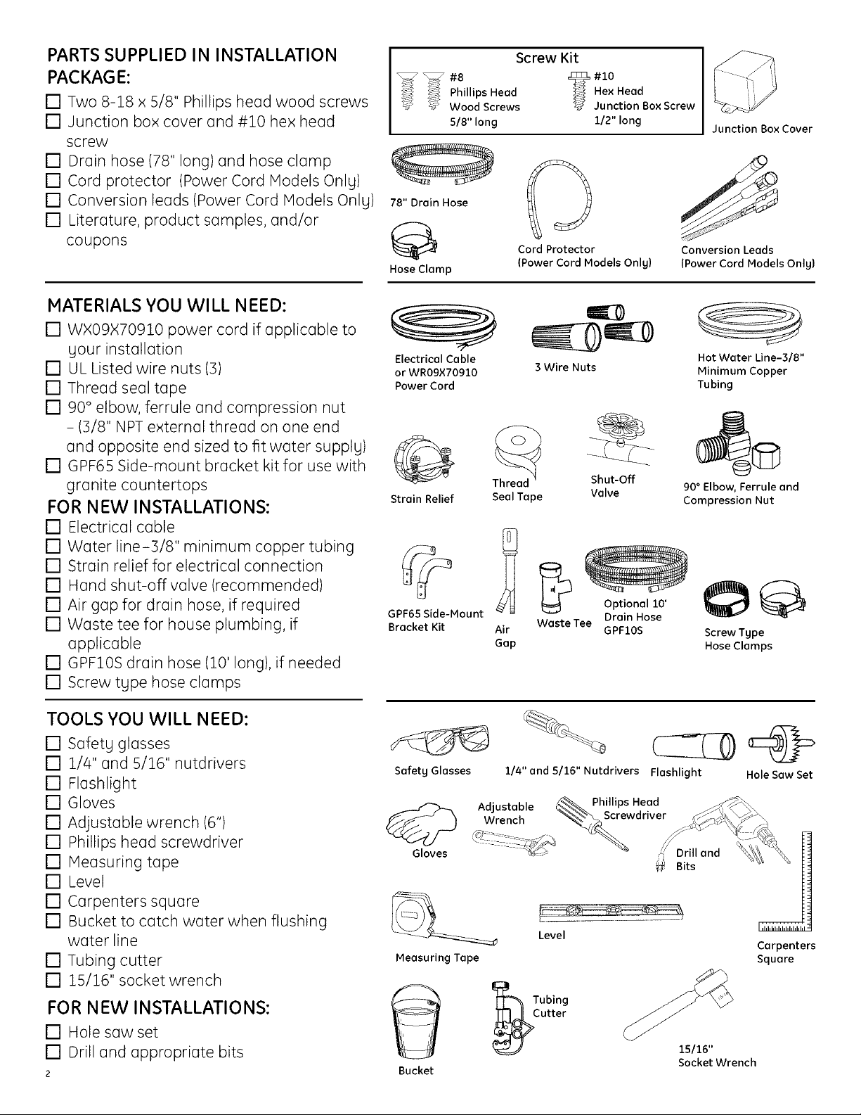
PARTS SUPPLIED IN INSTALLATION
PACKAGE:
[] Two 8-18 x 5/8" Phillips heod wood screws
[] Junction box cover and #10 hex head
screw
[] Drain hose (78" long) and hose clamp
[] Cord protector (Power Cord Models Onlg)
[] Conversion leads (Power Cord Models Onlg)
[] Literature, product samples, and/or
coupons
MATERIALS YOU WILL NEED:
[] WX09X70910 power cord if applicoble to
gour instollotion
[] UL Listed wire nuts (3)
[] Thread seol tape
[] 90 ° elbow, ferrule ond compression nut
- (3/8" NPT external thread on one end
and opposite end sized to fit water supplg)
[] GPF65 Side-mount brocket kit for use with
granite countertops
FOR NEW INSTALLATIONS:
[] Electrical cable
[] Water line-3/8" minimum copper tubing
[] Strain relief for electricol connection
[] Hond shut-offvalve (recommended)
[] Air gap for drain hose, if required
[] Waste tee for house plumbing, if
applicable
[] GPF10S drain hose (10' long), if needed
[] Screw tgpe hose clamps
Screw Kit
Phi,,psHeadHexHead
_S Wood Screws _ Junction Box Screw
5/8" long 1/2" long
78" Drain Hose
Cord Protector
Hose Clamp
Electrical Cable
or WR09×70910
Power Cord
Strain Relief Seal Tape Valve
GPF65 Side-Mount
Bracket Kit Air
(Power Cord Models Onlg)
3 Wire Nuts
Thread
Shut-Off
Waste Tee
Gap
Optional 10'
Drain Hose
GPFIOS
Junction Box Cover
Conversion Leads
(Power Cord Models Onlg)
Hot Water Line-3/8"
Minimum Copper
Tubing
90° Elbow, Ferrule and
Compression Nut
Screw Tgpe
Hose Clamps
TOOLS YOU WILL NEED:
[] Sofetg glosses
[] 1//4" and 5/16" nutdrivers
[] Flashlight
[] Gloves
[] Adjustable wrench (6")
[] Phillips head screwdriver
[] Meosuring tope
[] Level
[] Carpenters square
[] Bucket to catch water when flushing
water line
[] Tubing cutter
[] 15/16" socket wrench
FOR NEW INSTALLATIONS:
[] Hole sow set
[] Drill ond oppropriate bits
2
Safetg Glasses
Gloves
Measuring Tape
Bucket
1/4"and 5/16" Nutdrivers Flashlight
Adjustab e _ Phillips Head
... - _ Screwdriver
wrencn -_/_L_L-
Level
Tubing
utter
Hole Saw Set
Drill and
Bits
J
Carpenters
Square
15116"
SocketWrench
Installation Preparation-Enclosure
PREPARE DISHWASHER ENCLOSURE
P!_V_Vl=_;t_11_[_
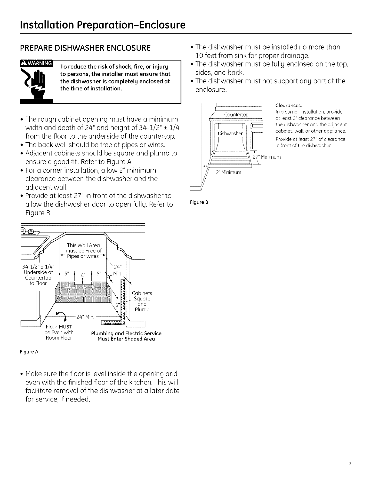
• The rough cabinet opening must have a minimum
width and depth of 24" and height of 34-1/2" _+1/4"
from the floor to the underside of the countertop.
• The back wall should be free of pipes or wires.
• Adjacent cabinets should be square and plumb to
ensure a good fit. Refer to Figure A
• For a corner installation, allow 2" minimum
clearance between the dishwasher and the
adjacent wall.
• Provide at least 27" in front of the dishwasher to
allow the dishwasher door to open fully. Refer to
Figure B
To reduce the risk of shock, fire, or injury
to persons, the installer must ensure that
the dishwasher is completely enclosed at
the time of installation.
• The dishwasher must be installed no more than
10 feet from sink for proper drainage.
• The dishwasher must be fullg enclosed on the top,
sides, and back.
• The dishwasher must not support ang part of the
enclosure.
Clearances:
Countertop
\ 27" Minimum
In a corner installation, provide
at least 2" clearance between
the dishwasher and the adjacent
cabinet, wall, or other appliance.
Provide at least 27" of clearance
in front of the dishwasher.
\
Figure B
This Wall Area
must be Free of
Pipes or
54-1/2" _+1/4"
Underside of
Countertop
to Floor
Cabinets
Square
and
Plumb
l
Floor MUST
be Even with
Room Floor
Figure A
Min.
Plumbing and Electric Service
Must Enter Shaded Area
• Hake sure the floor is level inside the opening and
even with the finished floor of the kitchen. This will
facilitate removal of the dishwasher at a later date
for service, if needed.
Installation Preparation-Drain
PREPARE DRAIN PLUMBING
Drain Requirements
• Followlocalcodes and ordinances.
• Drainhose must notexceed 10 feetinlength,
• A highdrainloopor airgap isrequired.See below.
Drain Method
The type of drain installation depends on the
following:
• Do local codes or ordinances require an air gap?
• Is waste tee less than 18" above the floor?
If the answer to either question is YES,on air gap
(Method 1) must be used. If both answers are NO,
either on air gap or a high drain loop (Method 2)
malj be used.
Special consideration for a dishwasher installed
on a pedestal
If the dishwasher is installed on an elevated
platform, a high drain loop of at least 32" above the
platform must be provided in addition to the air gap
requirement determined above. This is necessary for
proper drain performance.
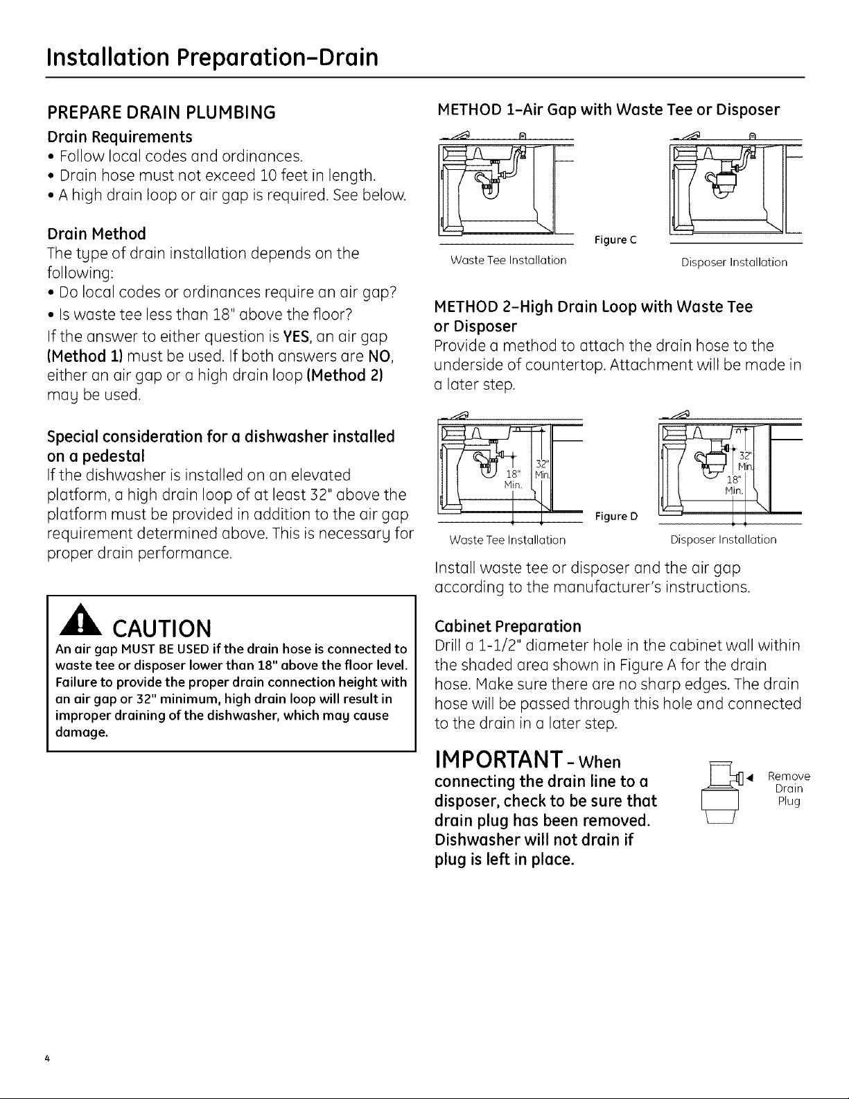
METHOD 1-Air Gap with Waste Tee or Disposer
Figure C
Waste Tee Installation
Disposer Installation
METHOD 2-High Drain Loop with Waste Tee
or Disposer
Provide a method to attach the drain hose to the
underside of countertop. Attachment will be made in
a later step.
n.
Waste Tee Installation
Figure D
Disposer Installation
Install waste tee or disposer and the air gap
according to the manufacturer's instructions.
CAUTION
An air gap MUST BE USED if the drain hose is connected to
waste tee or disposer lower than 18" above the floor level.
Failure to provide the proper drain connection height with
an air gap or 32" minimum, high drain loop will result in
improper draining of the dishwasher, which mag cause
damage.
Cabinet Preparation
Drill a 1-1/2" diameter hole in the cabinet wall within
the shaded area shown in Figure A for the drain
hose. Make sure there are no sharp edges. The drain
hose will be passed through this hole and connected
to the drain in a later step.
IMPORTANT- When
connecting the drain line to a
disposer, check to be sure that
drain plug has been removed.
Dishwasher will not drain if
plug is left in place.
_4 Remove
Drain
Plug
Installation Preparation-Electrical Supply
PREPARE ELECTRICAL WIRING
P"v._V#l.,'1:t_II_[_i
FOR PERSONAL SAFETY: Remove house
fuse or open circuit breaker before
beginning installation. Do not use an
extension cord or adapter plug with this
appliance.
Electrical Requirements
• This appliance must be supplied with 120V, 60 Hz.,
and connected to an individual properlg grounded
branch circuit, protected bg a 15 or 20 ampere
circuit breaker or time delay fuse.
• Wiring must be 2 wire with ground.
• If the electrical supply does not meet the above
requirements, call a licensed electrician before
proceeding.
Grounding Instructions-Permanent Connection
This appliance must be connected to a grounded
metal, permanent wiring sgstem, or an equipment
grounding conductor must be run with the circuit
conductors and be connected to the equipment
grounding terminal or lead on the appliance.
Grounding Instructions-Power Cord Models
This appliance must be grounded. In the event of a
malfunction or breakdown, grounding will reduce
the risk of electric shock bg providing a path of
least resistance for electric current. This appliance
is equipped with a cord having an equipment
grounding conductor and a grounding plug. The plug
must be plugged into an appropriate outlet that is
installed and grounded in accordance with all local
codes and ordinances.
The improper connection of the equipment
grounding conductor can result in electric
shock. Check with a qualified electrician or
service representative if gou are in doubt
that the appliance is properlg grounded.
Do not modifg the plug provided with the
appliance; if it will not fit the outlet, have
a proper outlet installed bg a qualified
technician.
/ I I \
/ I Receptacle
" I- Alternate -]" x
j Locaton _ _\
rT [- , ,,,
iiiJ I Receptacle -1-1/2" Dia.Hole (Max.)
_1_" I-'_L°cati°fT"l
,....-
Cabinet
fr3o
from _
Ground=_/_ _
Figure E White
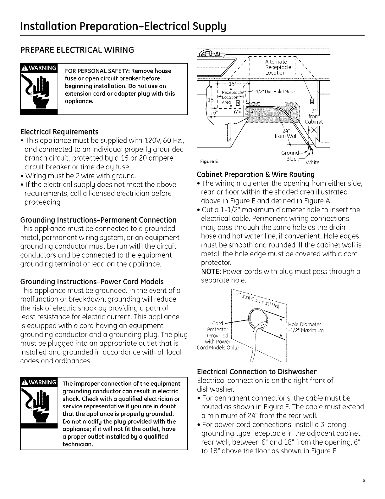
Cabinet Preparation & Wire Routing
• The wiring mag enter the opening from either side,
rear, or floor within the shaded area illustrated
above in Figure E and defined in Figure A.
• Cut a 1-1/2" maximum diameter hole to insert the
electrical cable. Permanent wiring connections
mag pass through the same hole as the drain
hose and hot water line, if convenient. Hole edges
must be smooth and rounded. If the cabinet wall is
metal, the hole edge must be covered with a cord
protector.
NOTE: Power cords with plug must pass through a
separate hole.
Cord Hole Diameter
Protector 1-1/2" Maximum
(Provided
with Power
Cord Models Onlg)
Electrical Connection to Dishwasher
Electrical connection is on the right front of
dishwasher.
• For permanent connections, the cable must be
routed as shown in Figure E.The cable must extend
a minimum of 24" from the rear wall.
• For power cord connections, install a 3-prong
grounding tgpe receptacle in the adjacent cabinet
rear wall, between 6" and 18" from the opening, 6"
to 18" above the floor as shown in Figure E.
Black _ /

Installation Preparation-Hot Water Supply
PREPARE HOT WATER SUPPLY
Hot Water Line
• The line may enter from either side, rear, or floor
within the shaded area shown in Figure F.
• The line may pass through the same hole as the
electrical cable and drain hose, or cut an additional
1-1/2" diameter hole to accommodate the water
line. If a power cord with plug is used, the water line
must not pass through the power cord hole.
The hot water supply line pressure must be at least 20 PSI.
Lower pressures could cause the water valve to leak and
cause water damage.
CAUTION
Cabinet Face_,-
Figure F
Water Line Connection
• Turn off the water supply.
• Install a hand shut-off valve in an accessible
location, such as under the sink. (Optional, but
strongly recommended and may be required by
local codes.)
• The water connection is on the left side of the
dishwasher. Install the hot water inlet line, using
3/8" or larger copper tubing. Route the line as
shown in Figure F and extend forward at least 19"
from rear wall.
• Adjust the water heater to deliver water between
120°F and 150°F.
• Flush water line to clean out debris. Use a bucket
to catch water and debris.
• The hot water supply line pressure must be
between 20 and 120 PSI.
Dishwasher Installation
CAUTION
Do not remove the wood base until you are ready to
install the dishwasher. The dishwasher will tip over
when the door is opened if the base is removed.
STEP 1: PREPARATION
Locate the items in the installation package and set
them aside for use in the listed steps.
• Screw kit-Steps 5 or 16 and 13
• Junction box cover-Steps 5 or 16
• Drain hose and drain hose clamp-Step 7
• Owners' Manual-Steps 18 and 21
• Product Samples and/or coupons-Step 21
• Conversion leads (Factory-equipped Power Cord
Models Only)-Appendix
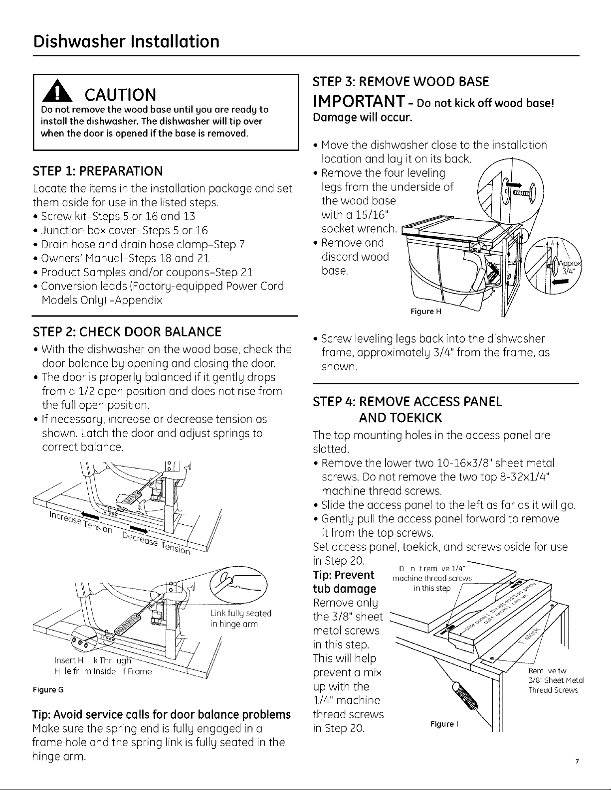
STEP 3: REMOVE WOOD BASE
IMPORTANT - Donotkick off wood base!
Damage will occur.
• Move the dishwasher close to the installation
location and lag it on its back.
• Remove the four leveling
legs from the underside of
the wood base
with a 15/16"
socket wrench.
discard wood
base.
STEP 2: CHECK DOOR BALANCE
• With the dishwasher on the wood base, check the
door balance bg opening and closing the door.
• The door is properly balanced if it gently drops
from a 1/2 open position and does not rise from
the full open position.
• If necessary, increase or decrease tension as
shown. Latch the door and adjust springs to
correct balance.
Link fully seated
in hinge arm
• Screw leveling legs back into the dishwasher
frame, approximately 3/4" from the frame, as
shown.
STEP 4: REMOVE ACCESS PANEL
AND TOEKICK
The top mounting holes in the access panel are
slotted.
• Remove the lower two 10-16x3/8" sheet metal
screws. Do not remove the two top 8-32xl/4"
machine thread screws.
• Slide the access panel to the left as far as it will go.
• Gently pull the access panel forward to remove
it from the top screws.
Set access panel, toekick, and screws aside for use
in Step 20. D n trem ve 1/4"_
Tip: Prevent machine thread screws /J_-
tub damage in this step _ _-_-_
the 3/8" sheet
emo eon
Insert H kThr uc
H lefr mlnside fFrame
Figure G
Tip: Avoid service calls for door balance problems
Make sure the spring end is fully engaged in a
frame hole and the spring link is full U seated in the
hinge arm.
in this step.
metalscrews "__ _ _7"11
This will help
prevent a mix _ Remvetw
up with the _ Thread Screws
1/4" machine
thread screws
in Step 20. Figure
3/8" Sheet Metal

Dishwasher Installation
STEP S: INSTALL POWER CORD
Skip this step if the dishwasher will be
permanently connected to the house electrical
system or has a factory installed power cord.
In this step you will need the junction box cover and
the #10 x 1/2" hex head screw from the screw kit set
aside in Step 1.
The power cord and connections must comply
with the National Electrical Code, Section/422 and/
or local codes and ordinances. Maximum power
cord length is 6 feet. Power Cord Kit WX09X70910
available for purchase from an authorized GE
Appliance Dealer, meets these requirements.
STEP 6: INSTALL 90 ° ELBOW
• Wrap a 90° elbow with thread seal tape.
• Thead the 90° elbow into the water valve.
• Do not over tighten the elbow; water valve bracket
could bend or the valve fitting could break.
• Position the end of the elbow to face the rear of
the dishwasher.
_Water Valve
Bracket
90 EIb w /
Tape
Figure K
m se
STEP 7: INSTALL DRAIN HOSE TO
DISHWASHER DRAIN PORT
Juncti n
B x Bracket
Black
\
Figure J
• Install strain relief in the junction box bracket.
• Insert the power cord through the strain relief and
tighten.
• Make sure black, white, and green dishwasher
wires are threaded through the small hole in the
junction box bracket.
• Connect power cord white (or ribbed) to
dishwasher white, black (or smooth) to dishwasher
black and ground to dishwasher green wire. Use
UL listed wire nuts of appropriate size.
• Install junction box cover using the #10 hex head
screw. Be sure wires are not pinched under the
cover
8
Skip this step if drain hose has been pre-installed.
In this step you will need the drain hose and clamp
set aside in Step 1.
IM PORTANT-Prevent drain hose damage
and possible leaks. Be careful not to nick or cut
the drain hose.
• Route the small end of the drain hose from the left
side of the dishwasher through the strain relief
attached to the dishwasher frame and toward
the center of the dishwasher as shown in Figures
Land M.
• Place the hose clamp over the small end of the
drain hose.
• Push the small end of the drain hose over the drain
port on the collection chamber making sure it is
fully seated against the hose stop.
• Tighten the hose clamp to at least 15 inch-pounds
of torque.
Note: The drain hose supplied with the dishwasher
///Relief
--_ / ,Strain
Figure L

Dishwasher Installation
is approximately 78" long. If a longer hose is needed,
a 10 foot long hose may be purchased from an
authorized GF appliance dealer. The 10 foot long
hose is part number GPF10S.
Hose Stop Do not use
Drain Hose Collection Chamber
Figure M Drain Port
this port if
present
STEP 9: INSERT DRAIN HOSE AND POWER
CORD, IF USED, THROUGH CABINET
• Upright the dishwasher and position it in front of
the cabinet opening.
• Insert the drain hose into the hole previously drilled
in the cabinet wall.
• If a power cord is used, guide the end of the cord
through a separate hole cut for the power cord.
The power cord should be routed directly to the rear
of the junction box avoiding contact with the door
spring and other dishwasher components.
Figure O
Tip: Avoid unnecessary service charges for drain
issues
Hake sure the drain hose connection is leak free
and the hose is routed through the strain relief so
it will not kink when the dishwasher is installed into
the cabinet.
STEP 8: POSITION WATER LINE AND
POWER SUPPLY
• Position the water supply line and house wiring on
the floor of the opening to avoid interference with
the base of dishwasher and components under
the dishwasher.
1
_Water
Line Supply
Tip: Avoid unnecessary service charges for no fill,
drain, or noise concerns
Position utility lines so they do not interfere with
anything under or behind the dishwasher.
STEP 10: INSTALL OPTIONAL GPF65 SIDE
MOUNT BRACKETS
Skip this step if the underside of countertop is
wood or wood like material.
• Purchase and install the GPF65 side mount bracket
kit if the underside of counter is granite or o
similar material that will not accept wood screws.
The GPF65 kit is available from authorized GE
appliance dealers.
• Refer to Figure P and follow the instructions
included in Side-
M unting v-
the kit. Brackets X
Tub Frame
Figure N
Bracket
Attachment
_ Optional Screws
Side-Mount (2 Each
Bracket Kit Figure P Side)

Dishwasher Installation
STEP 11: SLIDE DISHWASHER INTO CABINET
IMPORTANT - Do not push against the front
panel with knees. Damage will occur.
• Grasp the sides of the front panel and slide the
dishwasher into the opening o few inches at
o time. Pull the drain hose and power cord, if
equipped, through the holes in the adjacent
cabinet while sliding the dishwasher into position.
D n t push against
fr ntd rpanelwith
Figure Q
knee. Damaget the
d r panel will ccur.
STEP 12: POSITION AND LEVEL
DISHWASHER
IMPORTANT- Dishwasher must be level for
proper dish reck operation, wash performance,
and door operation. The dishwasher must be
leveled left to right and front to beck. This assures
that the dish recks will not roll in or out on their
own, circulation water will flow to the pump inlet,
and the door will close without hitting the side of
the tub.
• Remove the lower dish rack and place a level on
the door and lower rack track as shown in Figure R.
Check Level
Fr nt-t -Back
• Check the tub insulation blanket, if equipped, to
be sure it is smoothlg wrapped around the tub.
It should not be "bunched up" and it must not
interfere with the door springs. If the insulation
is "bunched up" or interfering with the springs,
straighten and re-center the blanket prior to sliding
the dishwasher into its final position.
• Make sure the drain hose is not kinked under or
behind the dishwasher.
• Make certain the house wiring, drain line, and
water line do not interfere with components under
the dishwasher.
• The dishwasher tub flange should be
approximatelg 5/4" behind the face of the adjacent
cabinet. Refer to Figure R.
Tip: Avoid unnecessarg service charges for panel
damage.
Do not press on the center of panel with hands or
knees when sliding dishwasher into position.
Figure R Side-t -Side
Level
• AdJust the level of the dishwasher bg individuallg
turning the four legs on the bottom of the
dishwasher as illustrated in Figure S.
[
to _ FigureS
• The dishwasher is properlg leveled when the level
indicator is centered left to right and front to back.
The dishwasher door should close without hitting
the sides of the tub.
• Replace the lower rock.
Tip: Avoid unnecessarg service charges for poor
wash performance and rack operation.
Pull the dish racks half wag out. Theg should remain
stationarg. Open and close the door. The door should
fit in the tub opening without hitting the side of the
tub. If the rocks roll on their own, or the door hits the
side of the tub, re-level the dishwasher.
Dishwasher Installation
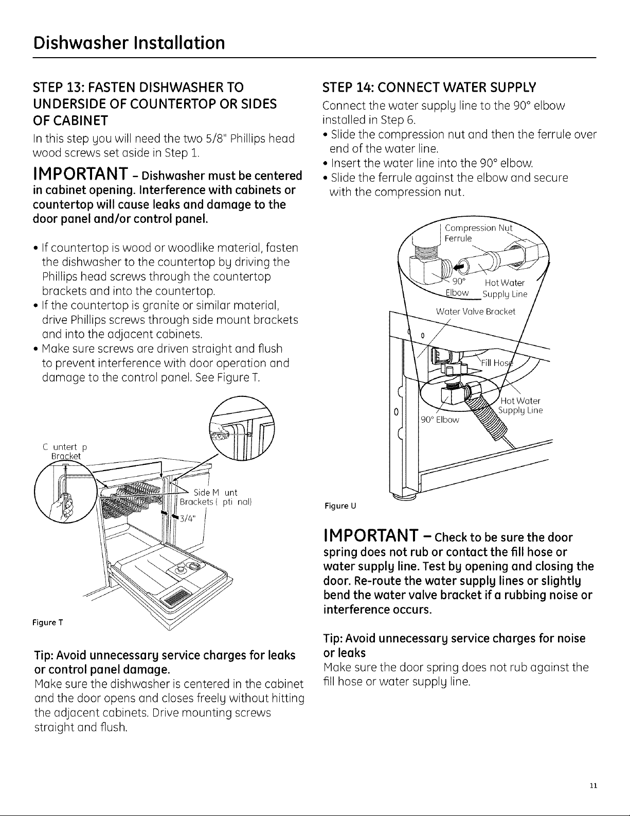
STEP 13: FASTEN DISHWASHER TO
UNDERSIDE OF COUNTERTOP OR SIDES
OF CABINET
In this step Uou will need the two 5/8" Phillips head
wood screws set aside in Step 1.
IMPORTANT - Dishwasher must be centered
in cabinet opening. Interference with cabinets or
countertop will cause leaks and damage to the
door panel and/or control panel.
• If countertop is wood or woodlike material, fasten
the dishwasher to the countertop by driving the
Phillips head screws through the countertop
brackets and into the countertop.
• If the countertop is granite or similar material,
drive Phillips screws through side mount brackets
and into the adjacent cabinets.
• Make sure screws are driven straight and flush
to prevent interference with door operation and
damage to the control panel. See Figure T.
STEP 14: CONNECT WATER SUPPLY
Connect the water supply line to the 90° elbow
installed in Step 6.
• Slide the compression nut and then the ferrule over
end of the water line.
• Insert the water line into the 90° elbow.
• Slide the ferrule against the elbow and secure
with the compression nut.
C untert p
Bracket
Side M unt
Brackets( pti nal)
Figure T
Tip: Avoid unnecessary service charges for leaks
or control panel damage.
Make sure the dishwasher is centered in the cabinet
and the door opens and closes freely without hitting
the adjacent cabinets. Drive mounting screws
straight and flush.
HotWater
SupplU Line
Figure U
IMPORTANT - Check to be sure the door
spring does not rub or contact the fill hose or
water supplg line. Test bg opening and closing the
door. Re-route the water supplg lines or slightlg
bend the water valve bracket if a rubbing noise or
interference occurs.
Tip: Avoid unnecessarg service charges for noise
or leaks
Make sure the door spring does not rub against the
fill hose or water supplu line.
11

Dishwasher Installation
STEP 15: CONNECT DRAIN LINE
The molded end of the drain hose will fit 5/8"
through 1" diameter inlet ports on the air gap, waste
tee or disposer.
• Determine the size of the inlet port
• Cut the drain hose connector on the marked line, if
required, to fit the inlet port.
Cutting Line
/.
Figure V
• If a longer drain hose is required, and gou did not
purchase the GPF10S drain hose, add up to 42"
length, for a total of 120" (10 feet) to the factorg
installed hose. Use 5/8" or 7/8" inside diameter
hose and a coupler to connect
the two hose ends.
IMPORTANT: Do not cut corrugated
portion of hose
Method 1 - Air gap with waste tee or disposer
__ r_ __ r¢
Waste Tee Installation Disposer Installation
Figure ×
Method 2 - "High drain loop" with waste tee or
disposer
Fasten the drain hose to the underside of the
countertop with a hanger.
32"
connection
with hose
Secure the _
HoseClamp
clamps. Coupler
Hose Clamp
Figure W
IMPORTANT - Total drain hose length must
not exceed 10 feet for proper drain operation.
• Connect drain line to air gap, waste tee, or disposer
using the previouslg determined method. Secure
the hose with a screw tgpe clamp.
Waste Tee Installation
Figure ¥
Disposer Installation
IMPORTANT - When connecting the drain
line to a disposer, check to be sure that the drain
plug has been removed. Dishwasher will not drain
if plug is left in place.
Drain
_4 Remove
Tip: Avoid unnecessary service call charges
for a no drain complaint
Make sure any excess drain hose has been pulled
through the cabinet opening. This will prevent
excess hose in the dishwasher cavitg from
becoming kinked or crushed bg the dishwasher.
Make sure the disposer plug has been removed if
the drain hose is connected to a disposer.
Plug

Dishwasher Installation
STEP 16: CONNECT POWER SUPPLY
If a power cord with plug is alreadg installed,
proceed to Step 17.
If the dishwasher came with a factory-installed
power cord and you want to convert it to a
permanent connection, refer to the instructions on
page 16.
If house wiring is not 2-wire with a ground
wire, a ground must be provided bg the
installer.
When house wiring is aluminum, be
sure to use U.L listed anti-oxidant compound
and aluminum-to-copper connectors.
• Secure house wiring to the back of the junction
box bracket with a strain relief.
• Locate the three dishwasher wires, (white, black
and green) with stripped ends. Insert dishwasher
wires through the small hole in the junction box
bracket. Use UL listed wire nuts of appropriate size
to connect incoming ground to green, white to
white and black to black.
Note: Checkthot home leod ore
threoded through moll hole in brocket
White
Junction Ground
s ox s rocket
STEP 17: INSTALL JUNCTION BOX COVER
If junction box cover is alreadg installed, skip to
Step 18.
In this step you will need the junction box cover and
the #10 hex head screw from the screw kit set aside
in Step 1.
• Install the junction box cover using the #10 hex
head screw. Check to be sure that wires are not
pinched under the cover.
STEP 18: PRE-TEST CHECK LIST
[] Verify that power is turned off at the source.
[] Open the dishwasher door and remove all foam
and cardboard packaging.
[] Read the Owner's Manual to familiarize yourself
with the operation of the dishwasher.
[] Check to be sure that the wiring is secure
under the dishwasher, and not pinched or in
contact with door springs or other dishwasher
components.
[] Check that the door spring does not contact the
water line, fill hose, or adjacent cabinets. See
Steps 13 and 14
[] Pull lower rack about halfway out. Check to be
sure it does not roll back into dishwasher or
further out. If it does, re-level the dishwasher.
See Step 12
[] Check to be sure control panel does not touch
adjacent cabinets. If it does, reposition the
dishwasher. See Step 13
[] Turn on the hot water faucet at the sink to verify
that the water temperature is at least 120°F
and not more than 150°F. Adjust water heater
if necessary.
[] Add two quarts of water to the bottom of the
dishwasher to lubricate the pump seal.
[] Turn on water supply.
[] Check for water leaks. Tighten connections if
necessary. See Step 14
[] Remove the protective film if present from the
control panel, access panel and door panel.
13

Dishwasher Installation
STEP 19: DISHWASHER WET TEST
CHECK LIST
[] Turn on power supply or if power cord is used,
plug it into the wall outlet.
[] Latch dishwasher door.
[] For electronic dishwashers, select the normal
cycle and press the start pad one time.
C_;_ Options 0
[] For dial models, press the normal and hot start
pads, if model has them, and then turn control
dial just enough to start dishwasher. Be careful
not to turn the dial past the first water fill. Dial
should point to "Hot Start Option" or "Hot Pre-
wash Option" depending on model.
- Check the electrical connection to the water
valve. The red electrical connector should be
plugged into the dishwasher water valve. If it is
not plugged in, turn off electrical power to the
dishwasher. Plug the red connector into the dish-
washer water valve and then restore power.
ii Red C nnector
Cycles Options op_oo sto,,
_ _ _ _ _ on
Appearance varies by model. Not all models have pushbuttons.
LightWash
[] Check to be sure that water enters the dish-
washer. This could take up to/4 minutes.
If water does not enter the dishwasher
- Check to be sure that the water is turned on
- Lightly tap the flood float cover to
dislodge a stuck flood float.
Cover
[] Check for leaks under the dishwasher. If a leak is
found, turn off power, tighten connections and
restore power.
[] Check for leaks around the door. A leak around
the door could be caused by the dishwasher door
rubbing or hitting adjacent cabinets. Reposition
the dishwasher if necessary. See Steps 11,12
and 13.
[] Host dishwasher models will drain about 3 min-
utes after the first fill. Check the drain line for
leaks when dishwasher drains. If leaks are found,
turn off power, correct as necessary and then
restore power.
[] Open the dishwasher door and make sure most
of the water has drained. If the water does not
drain, check to be sure disposer plug has been
removed and/or air gap is free of debris.
[] Let the dishwasher run through another fill and
drain cycle. Check again to be sure there are no
leaks.
[] At the end of the second drain, push the reset pad
on electronic models. For dial models, unlatch the
door and rotate the dial to the "OFF" position.
14
Dishwasher Installation
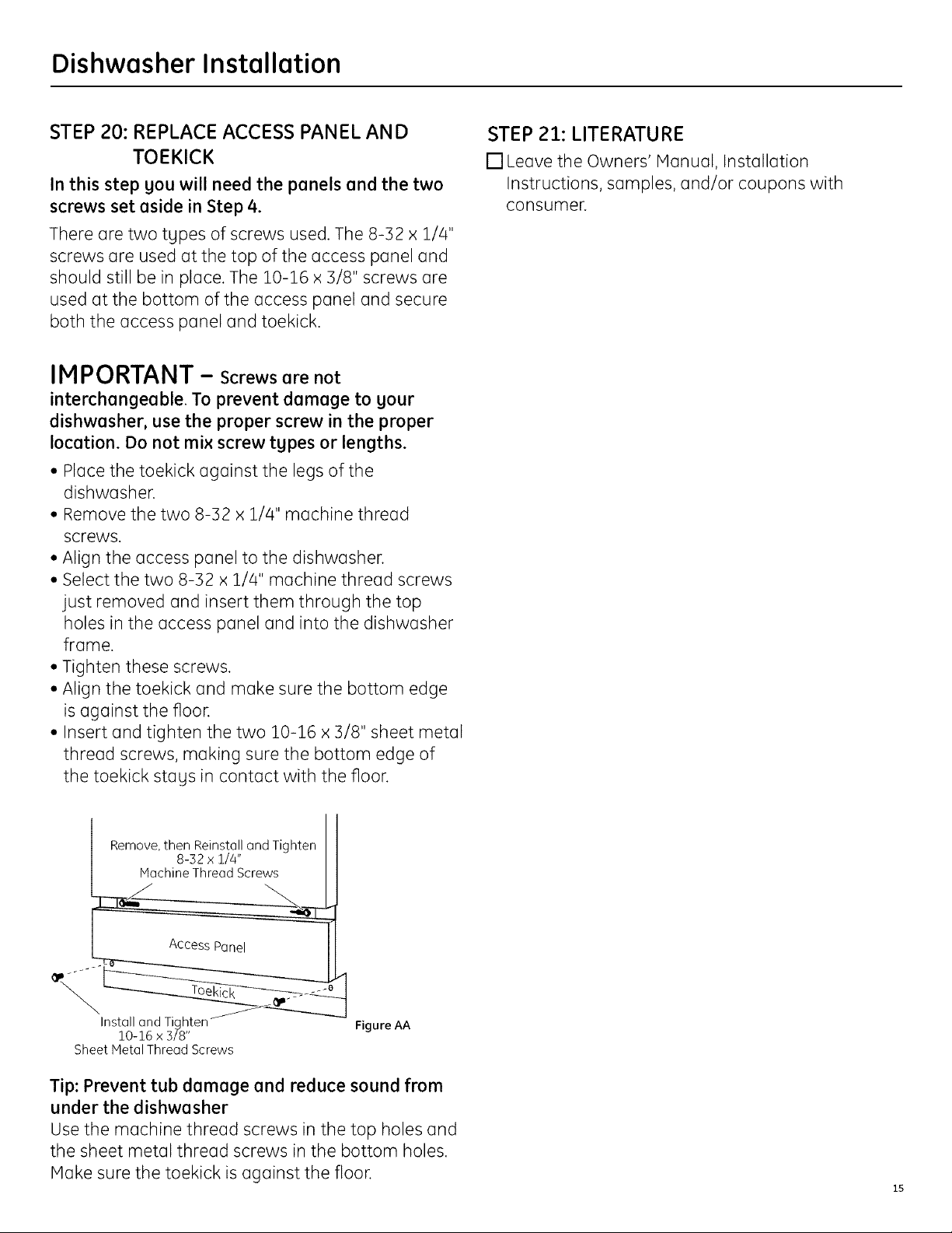
STEP 20: REPLACE ACCESS PANEL AND
TOEKICK
In this step gou will need the panels and the two
screws set aside in Step 4.
There are two tgpes of screws used. The 8-32 x 1/4"
screws are used at the top of the access panel and
should still be in place. The 10-16 x ]/8" screws are
used at the bottom of the access panel and secure
both the access panel and toekick.
IMPORTANT - Screws are not
interchangeable. To prevent damage to gour
dishwasher, use the proper screw in the proper
location. Do not mix screw tgpes or lengths.
• Place the toekick against the legs of the
dishwasher.
• Remove the two 8-32 x 1//4" machine thread
screws.
• Align the access panel to the dishwasher.
• Select the two 8-32 x 1//4" machine thread screws
just removed and insert them through the top
holes in the access panel and into the dishwasher
frame.
• Tighten these screws.
• Align the toekick and make sure the bottom edge
is against the floor.
• Insert and tighten the two 10-16 x 3/8" sheet metal
thread screws, making sure the bottom edge of
the toekick stags in contact with the floor.
STEP 21: LITERATURE
[] Leave the Owners' Hanual, Installation
Instructions, samples, and/or coupons with
consumer.
Remove, then Reinstall and Tighten
Install and Tighten
10-16 x 3/8"
Sheet Hetal Thread Screws
8-52 x 1/4"
Machine Thread Screws
Access Panel
Figure AA
Tip: Prevent tub damage and reduce sound from
under the dishwasher
Use the machine thread screws in the top holes and
the sheet metal thread screws in the bottom holes.
Hake sure the toekick is against the floor.

Appendix
CONVERTING DISHWASHER WITH FACTORY
EQUIPPED POWER CORD TO A PERMANENT
CONNECTION
This procedure requires the conversion leads set
aside in Step 1.
• Make sure the power cord for the dishwasher is
unplugged from the wall outlet.
• Remove screw from junction box cover and
remove cover if present.
• Disconnect the three power cord conductors from
the dishwasher harness. Figure BB
• Remove and discard the power cord.
• Connect the conversion harness (included with
dishwasher) to the dishwasher harness bg
connecting like-colored wires. Figure CC
• Return to Step 16 in these instructions to complete
the conversion.
Figure BB
/
/
/
Remove
StroinRelief
/
/
/
Disconnect
Powercord \
-\
\
SPECIFICATIONS SUBJECT TO CHANGE WITHOUT NOTICE
GEConsumer & Industrial
General Electric Company
Louisville, Kentuckg 40225
ge.com
Figure CC
Conversion Harness
Pub. No. 31-30218
Dwg. No. 206C1559P158
ND 06H-1949 (10/06)
 Loading...