

Hotpoint H562 IX, H562 WH, H562 BK, H572 IX, H592 IX Instruction Manual
Istruzioni per l’uso
CAPPA
I
Italiano, 1
F
Français, 25
NL
Nederlands, 49
H562 IX
H562 WH
H562 BK
H572 IX
H592 IX
GB
English, 9
E
Español, 33
D
Deutsch, 17
P
Portoguês, 41
Sommario
I
Installazione, 2-3
Montaggio
Informazioni tecniche, 4
Collegamento elettrico
Dati tecnici
Descrizione, 5
Versione filtrante
Versione aspirante
Funzionamento, 6
Comandi
Manutenzione, 7
Pulizia della cappa
Pulizia dei filtri antigrasso
Sostituzione dei filtri carbone
Sostituzione delle lampade
Precauzioni e consigli, 8
Sicurezza generale
Scarico dell’aria
Smaltimento
Installazione
Montaggio
I
Prima di procedere alle operazioni di montaggio,
per una più facile manovrabilità dell'apparecchio
disinserire la griglia metallica (per le istruzioni vedere
paragrafo “Pulizia del filtro antigrasso” sotto il capitolo “Manutenzione”).
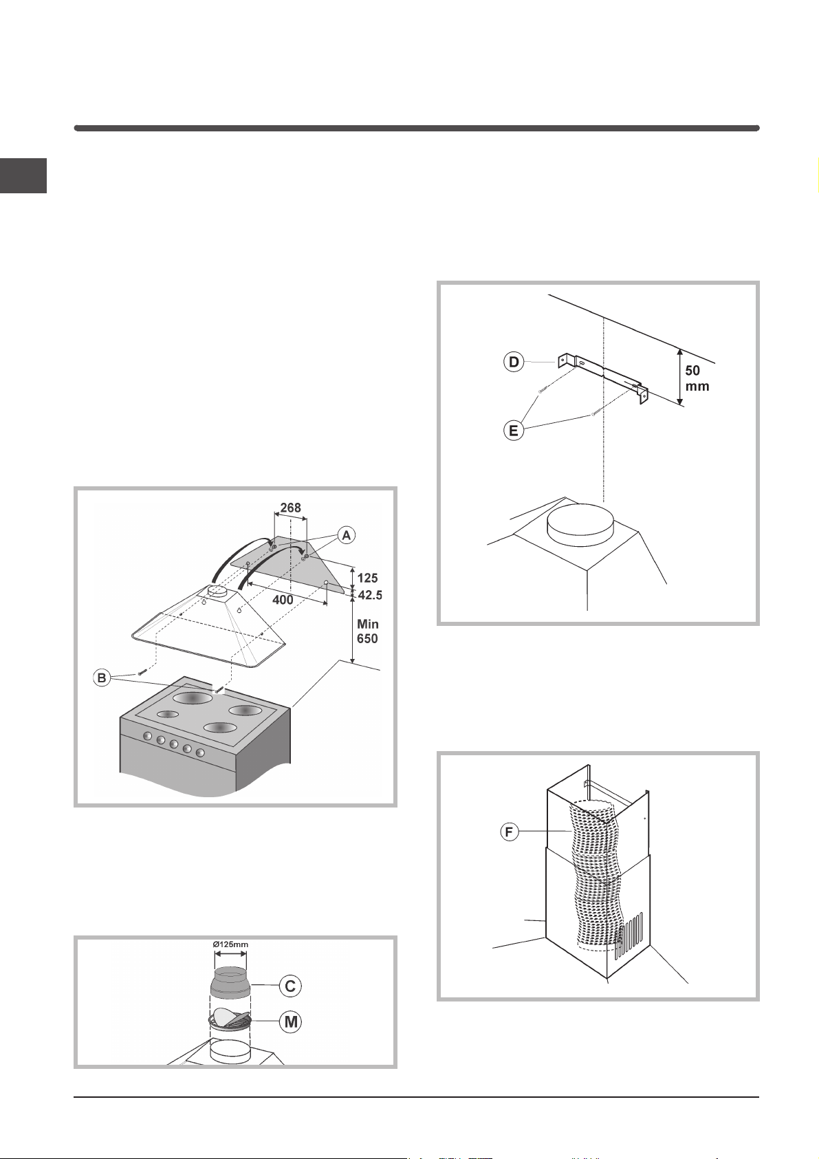
Fissaggio a muro
1) Tracciare sulla parete una linea, sulla verticale del
piano di cottura. Segnare sulla parete i 4 fori da
fare (fori A e fori B) rispettando le misure indicate
nella figura sotto.
2) Effettuare i fori (ø 8 mm) ed applicare i 4 tasselli in
dotazione.
3) Inserire solamente 2 viti, nei fori posti piu’ in alto
(A) ed agganciarvi la cappa.
4) Procedere al fissaggio definitivo inserendo altre 2
viti nei fori B.
Fissaggio del tubo decorativo
1) Appoggiare la staffa (D) a 50 mm dal soffitto
e posizionarla sulla verticale della cappa.
Con un pennarello segnare sulla parete i 2 fori;
effettuare i 2 fori ed inserire 2 tasselli.
2) Fissare la staffa alla parete mediante 2 viti (E).
5) Solamente per le versioni aspiranti:
- posizionare la flangia (M) sopra la bocca uscita
aria del motore ed esercitare una leggera pressione.
- la bocca uscita aria della cappa ha diametro 150
mm; se si ha necessità di un diametro inferiore, si
puo’ montare la riduzione (C).
3) Solamente per le versioni aspiranti: collegare la
bocca uscita aria della cappa al foro di scarico
dell’aria, tramite un tubo flessibile (F) di diametro
150 mm. Bloccare il tubo flessibile con delle
fascette metalliche (tubo e fascette non sono in
dotazione).
2

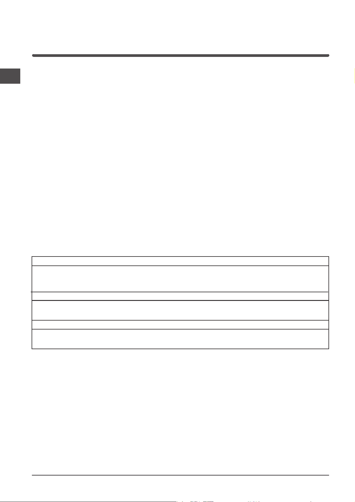
4) Solamente per le versioni filtranti: fissare il deflettore aria (G) al tubo inferiore utilizzando 2 viti.
5) Effettuare il collegamento elettrico della cappa
mediante il cavo di alimentazione (riferimento
paragrafo “Collegamento elettrico”).
6) Inserire il tubo decorativo appoggiandolo sulla
cappa; sollevare il tubo superiore fino al soffitto
e fissarlo tramite le 2 viti (H).
7) Solamente per le versioni filtranti;
nella versione filtrante è necessario l’uso del filtro/i
carbone, per cui, nel caso non sia già installato
nella cappa, montatelo/i come segue:
agganciate il filtro carbone con movimento rotatorio,
in senso anti-orario.
Nella versione aspirante il/i filtro/i al carbone non è
necessario, per cui se è già installato/i nella cappa
rimuovetelo/i.
I
3
Informazioni tecniche
Collegamento elettrico
I
! Predisporre l’alimentazione elettrica entro l’ingom-
bro del tubo decorativo.
! Nell’operazione di collegamento elettrico verificare
che i valori di tensione corrispondano con
quelli indicati nella targa inserita all’interno
dell’apparecchio.
! Se il Vostro apparecchio non è provvisto di cavo
flessibile non separabile e di spina, o di altro
dispositivo che assicuri la onnipolare disinserzione
dalla rete, con una distanza di apertura dei contatti
di almeno3 mm, allora tali dispositivi di separazione
dalla rete devono essere previsti nell'installazione
fissa.
! Se il Vostro apparecchio è provvisto di cavo
alimentazione e di spina, porre l'apparecchio
in modo che la spina sia accessibile.
Dati tecnici
Modello H562IX / H562WH / H562 BK H572IX H592IX
Dimensioni larghezza 59.8 cm larghezza 69.8 cm larghezza 89.8 cm
Peso lordo 12.7 Kg 14 Kg 16 Kg
Assorbimento Totale 330 W Totale 330 W Totale 330 W
Portata 770 m3/h 770 m3/h 770 m3/h
Filtro antigrasso
Superficie
di aspirazione 1487 cm
altezza 79 / 112 cm altezza 79 / 112 cm altezza 79 / 112 cm
profondità 50.7 cm profondità 50.7 cm profondità 50.7 cm
Ø del tubo di scarico 15 cm Ø del tubo di scarico 15 cm Ø del tubo di scarico 15 cm
Motore 1x250 W Motore 1x250 W Motore 1x250 W
Lampade 2x40 W Lampade 2x40 W Lampade 2x40 W
2
1487 cm
2
2287 cm
2
4
Descrizione
La cappa puo’ essere in versione filtrante o in versione
aspirante.
Decidere sin dall’inizio il tipo di installazione.
Per una maggiore efficienza, consigliamo di installare
la cappa in versione aspirante (se possibile).
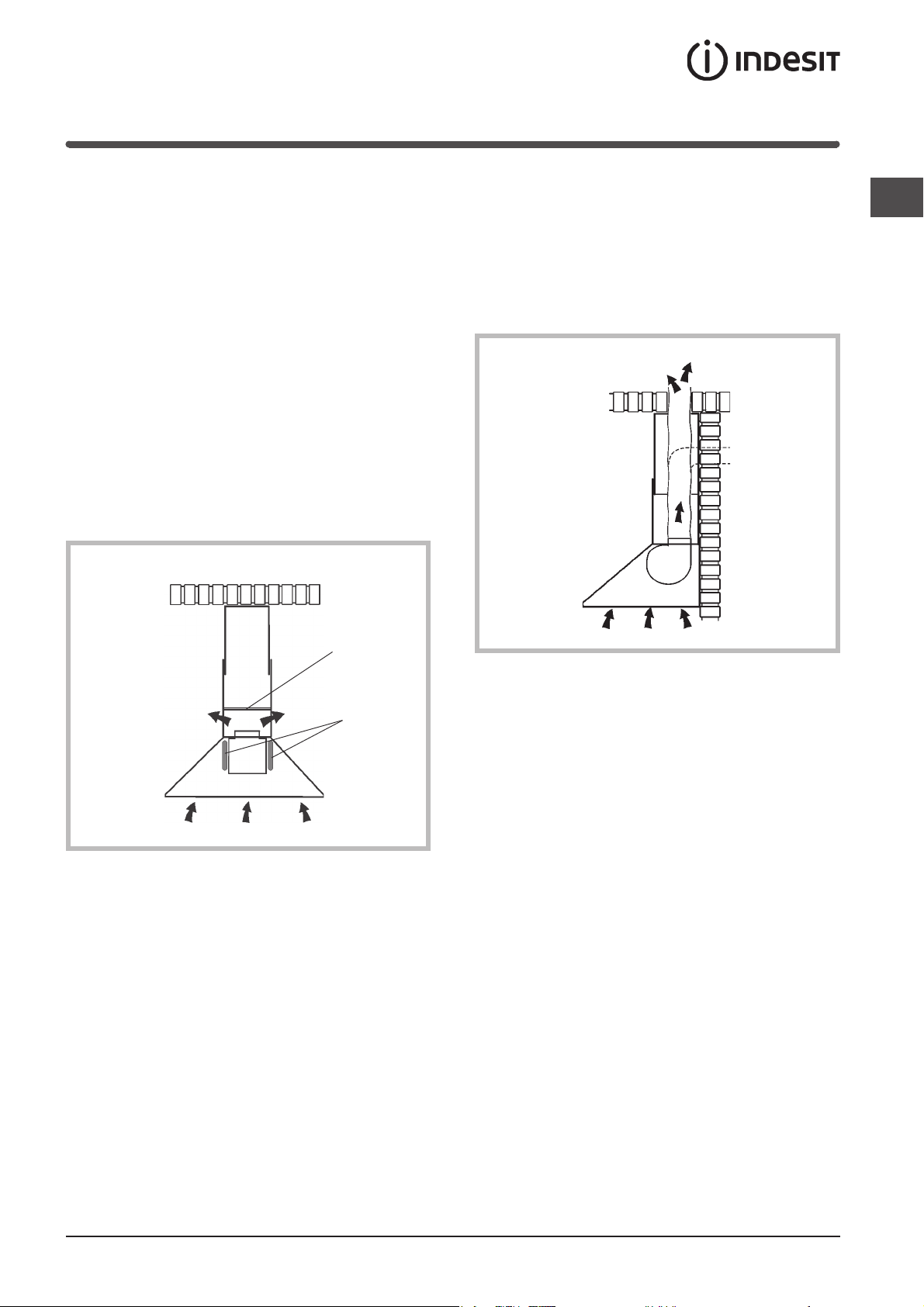
Versione filtrante
La cappa aspira l’aria della cucina impregnata di fumi
e di odori, depurandola attraverso il filtro anti-grasso
ed il filtro carbone per poi re-immetterla pulita
nella stanza.
Per questa versione è necessario un deflettore aria
(N) e 2 filtri al carbone (L).
Per una costante efficienza, è necessario sostituire
periodicamente i filtri al carbone.
Se la cappa non è dotata dei filtri al carbone,
richiederlo al rivenditore.
Versione aspirante
I
La cappa aspira l’aria della cucina impregnata di fumi
e di odori facendola passare attraverso il filtro
anti-grasso, poi la espelle all’esterno attraverso
un condotto di scarico.
In questa versione non è necessario utilizzare i filtri
al carbone.
N
L
5

Funzionamento
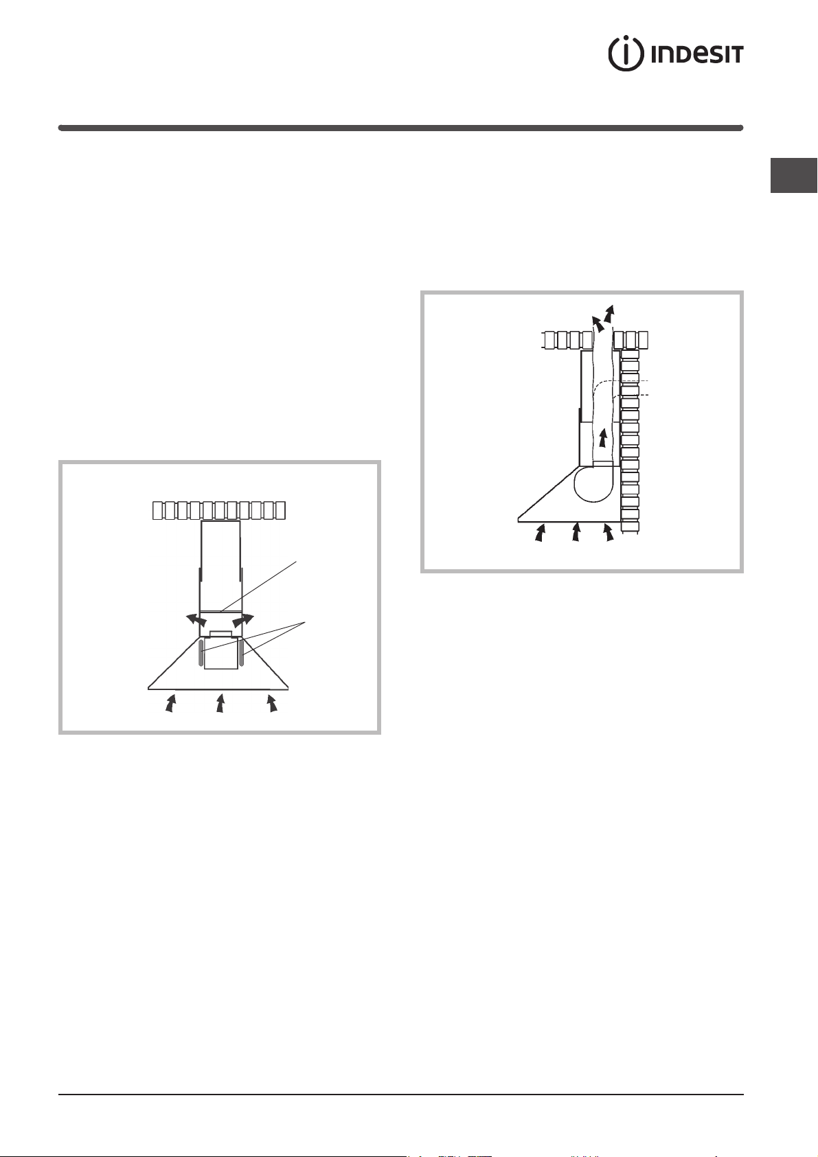
Comandi
I
E
A - Tasto illuminazione
Accende / Spegne le luci.
B - Tasto ON/OFF motore
Attiva / Disattiva il motore.
Il motore si attiva alla prima velocità.
C - Tasto seconda velocità
Attiva / Disattiva il motore.
Aziona il motore alla 2
a
velocità
A
B
C
D - Tasto terza velocità
Attiva / Disattiva il motore.
Aziona il motore alla 3
E - Spia di funzionamento del motore
D
a
velocità
6
Manutenzione
! Prima di procedere a qualsiasi operazione di pulizia
o manutenzione è necessario togliere tensione.
! Per evitare un possibile rischio di incendio attenersi
alle istruzioni indicate per la pulizia dei filtri
antigrasso e la rimozione di eventuali depositi
di grasso sull’apparecchio.
Un'accurata manutenzione garantisce un buon funzionamento ed un buon rendimento nel tempo.
Pulizia della cappa
La rimozione di eventuali depositi di grasso
dall'apparecchio va effettuata periodicamente in
rapporto all'uso (almeno ogni 2 mesi).
Evitare l'uso di prodotti contenenti abrasivi o corrosivi.
Per la pulizia esterna di apparecchi verniciati adoperare
un panno inumidito con acqua tiepida e detersivo
neutro; per la pulizia esterna di apparecchi in acciaio,
rame od ottone è consigliato l'uso di prodotti specifici,
seguendo le istruzioni indicate sul prodotto;
per la pulizia interna dell'apparecchio usare
un panno/pennello imbevuto di alcool etilico
denaturato.
Sostituzione dei filtri carbone
I
Nel caso d'uso dell'apparecchio in versione filtrante,
sarà necessario sostituire i filtri al carbone (L).
Rimuovere i filtri carbone con movimento rotatorio, in
senso orario.
L
Sostituire i filtri carbone mediamente ogni 6 mesi,
in rapporto all'uso.
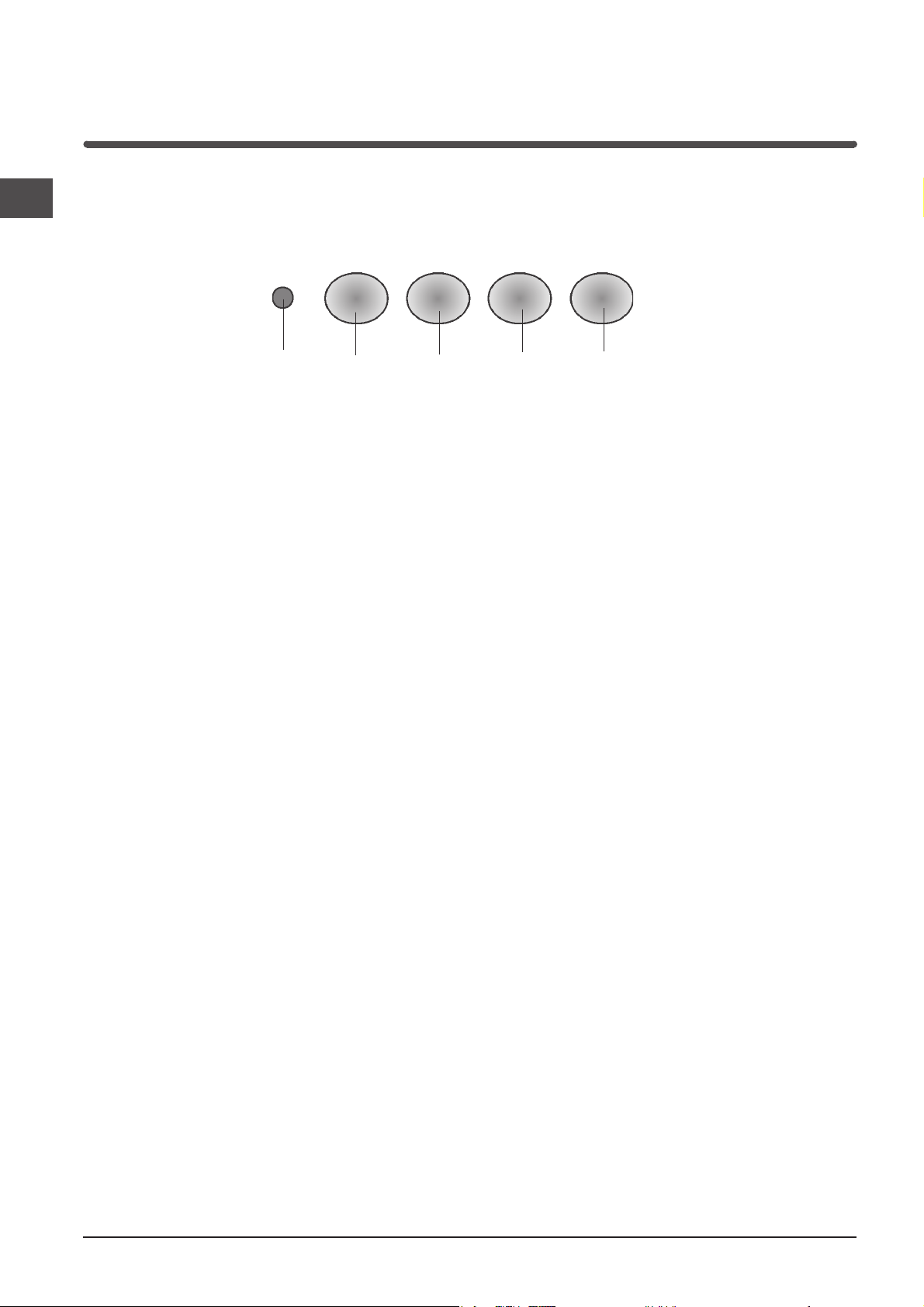
Pulizia dei filtri antigrasso
Per togliere i filtri antigrasso, in corrispondenza
della maniglia spingere il fermo verso l'interno e tirare
il filtro verso il basso.
Lavare i filtri con detersivo neutro a mano
o in lavastoviglie. Nel caso di lavaggio in lavastoglie,
un eventuale scolorimento non compromette in
nessun modo la funzionalità dei filtri.
Sostituzione delle lampade
Prestare particolare ATTENZIONE nell’effettuare
questa operazione, inoltre ricordare che è necessario
togliere la tensione.
Dopo aver tolto i filtri antigrasso, rimuovere la
plafoniera operando manualmente dall’interno della
cappa. Esercitare una leggera pressione sulla parte
mobile dei 2 fermi e sganciarla quindi dall’esterno.
Svitare la lampada e sostituirla con una lampada
dello stesso tipo.
Rimontare la plafoniera spingendola in sede dal lato
esterno.
Pulire i filtri antigrasso mediamente ogni 2 mesi, in
rapporto all'uso.
7

Precauzioni e consigli
Sicurezza generale
I
! La distanza minima tra la superficie di supporto
delle pentole sul piano di cottura e la parte inferiore
della cappa deve essere 65 cm. Se le istruzioni
per l’installazione del piano di cottura specificano
una distanza maggiore, questa deve essere tenuta
in considerazione.
! Questo apparecchio presenta accorgimenti
tecnici costruttivi tali da essere annoverato
nella classe di isolamento II e pertanto non
deve essere collegato a terra.
! Evitare l’uso di materiali che causano fiammate
(flambè) nelle immediate vicinanze dell’apparecchio.
! Nel caso di fritture fare particolarmente attenzione
al pericolo di incendio che costituiscono olio
e grassi. Particolarmente pericoloso per la
sua infiammabilità è l’olio già usato.
! Non usare griglie elettriche scoperte.
! Si raccomanda di non posizionare pesi eccessivi
sopra la cappa.
Scarico dell’aria
di calore. Pertanto attrezzare il locale con
delle prese d’aria che alimentino un flusso costante
di aria fresca.
Smaltimento
La direttiva Europea 2002/96/CE sui rifiuti di
apparecchiature elettriche ed elettroniche (RAEE),
prevede che gli elettrodomestici non debbano essere
smaltiti nel normale flusso dei rifiuti solidi urbani.
Gli apparecchi dismessi devono essere raccolti
separatamente per ottimizzare il tasso di recupero
e riciclaggio dei materiali che li compongono
ed impedire potenziali danni per la salute e l’ambiente.
Il simbolo del cestino barrato è riportato su tutti
i prodotti per ricordare gli obblighi di raccolta separata.
Per ulteriori informazioni, sulla corretta dismissione
degli elettrodomestici, i detentori potranno rivolgersi
al servizio pubblico preposto o ai rivenditori.
Se il vostro apparecchio deve essere istallato in
versione Aspirante, predisporre il foro ed il condotto di
scarico dell’aria.
Per ottenere condizioni ottimali nelle versioni aspiranti,
utilizzare un tubo per lo scarico dell’aria che abbia:
lunghezza minima indispensabile, minor numero
possibile di curve (angolo massimo della curva: 90°),
materiale approvato normativamente (a seconda dello
Stato), lato interno piú liscio possibile. Si consiglia
inoltre di evitare cambiamenti drastici di sezione del
tubo (diametro: 150 mm).
! L'aria raccolta non deve essere convogliata
in un condotto usato per lo scarico di fumi di
apparecchi alimentati con energia diversa da quella
elettrica (impianti di riscaldamento centralizzati,
termosifoni, scaldabagni ecc.).
! Per lo scarico dell'aria da evacuare rispettare
le prescrizioni delle autorità competenti.
Inoltre l'aria da scaricare non deve essere eliminata
attraverso una cavità del muro a meno che tale
cavità non sia destinata a questo scopo.
! Prevedere un'adeguata areazione del locale quando
una cappa e apparecchi alimentati con energia
diversa da quella elettrica (stufe a gas, ad olio,
a carbone ecc), vengono usati
contemporaneamente. Infatti la cappa aspirante
evacuando l'aria potrebbe creare una pressione
negativa nella stanza. La pressione negativa
del locale non deve superare i 0,04 mbar, evitando
così il risucchio dei gas di scarico della fonte
8
Instructions for use
HOOD
I
Italiano, 1
F
Français, 25
NL
Nederlands, 49
H562 IX
H562 WH
H562 BK
H572 IX
H592 IX
GB
English, 9
E
Español, 33
D
Deutsch, 17
P
Portoguês, 41
Contents
GB
Installation, 10-11
Assembly
Technical information, 12
Electrical connection
Technical data
Description, 13
Filtering version
Ducting version
Operation, 14
Controls
Maintenance,15
Cleaning the hood
Cleaning the grease filters
Replacing the charcoal filters
Replacing the lamps
Precautions and tips, 16
General safety
Air vent
Disposal
9
Installation
GB
Assembly
Before proceeding with the assembly operations,
remove the metal grille so that the hood is easier
to handle (for the instructions see the paragraph
“Cleaning the grease filter” in the chapter on
“Maintenance”).
Fixing to the wall
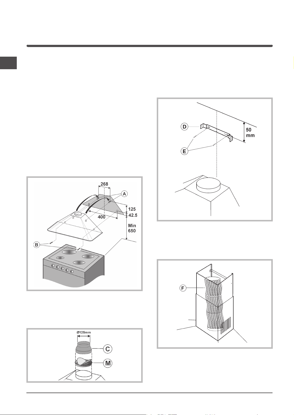
1) Draw a line on the wall along the vertical axis of
the hob. Mark the 4 holes (A and B) to be drilled
on the wall, respecting the measurements
indicated in the figure below.
2) Drill the holes (8 mm ø) and fit the 4 screw
anchors provided.
3) Fit only 2 screws in the topmost holes (A) and
hook the hood onto them.
4) Proceed with final fixing using a further 2 screws
in the holes (B).
Securing the decorative flue
1) Place the bracket (C) 50 mm from the ceiling and
position it on the vertical axis of the hood.
With a felt-tip pen, mark the 2 holes on the wall;
drill the 2 holes and fit 2 screw anchors.
2) Fix the bracket to the wall using 2 screws (E).
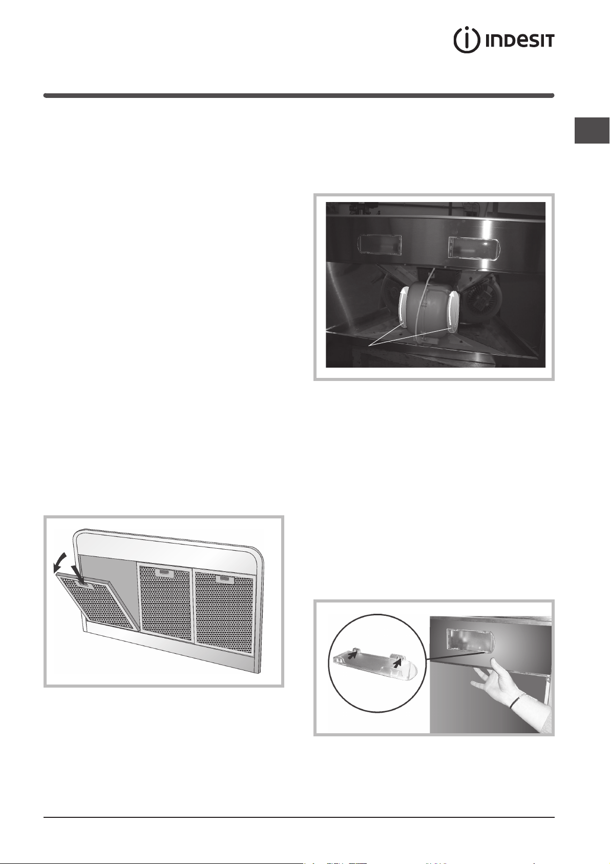
5) Only for the ducting versions:
- set the flange (M) over the motor and press
slightly.
- the air vent of the hood has a diameter of 150
mm; if you need a smaller diameter, fit the
reducer (C).
3) Only for the ducting versions: Connect the air vent
of the hood to the air vent hole using a flexible
hose (F) of 150 mm diameter. Lock the flexible
hose with some metal hose clamps (hose and
clamps not provided).
10
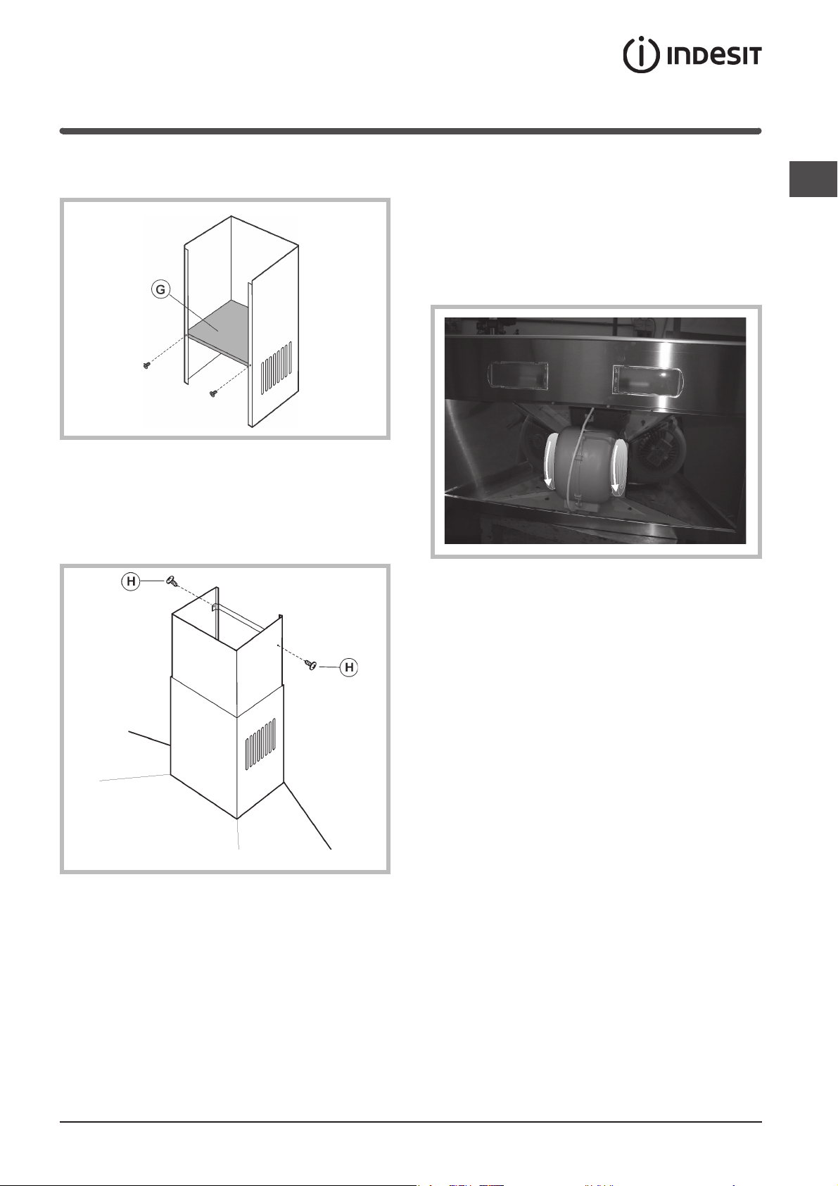
4) Only for filtering versions: Secure the air baffle (G)
to the lower flue using 2 screws.
5) Make the electrical connection of the hood by
means of the power cable (refer to the paragraph
“Electrical connection”).
6) Fit the decorative flue resting it on the hood Lift
the upper flue up to the ceiling and secure it by
means of the 2 screws (H).
7) Only for filtering versions;
One or more charcoal filters are required for the
filtering version. If they are not yet installed in the
hood, fit it/them as follows:
fit the charcoal filter by turning it anticlockwise.
The ducting version does not require the charcoal
filter/s, therefore, if already fitted in the hood remove
it/them.
GB
11
Technical information
GB
Electrical connection
! Arrange the electrical power supply within the
decorative flue dimensions.
! When making the electrical connections, check that
the voltage values correspond to those indicated on
the data plate inside the appliance itself.
! In case your appliance is not furnished with a non
separating flexible cable and has no plug, or has not
got any other device ensuring omnipolar
disconnection from the electricity main, with a
contact opening distance of at least 3 mm, such
separating device ensuring disconnection from the
main must be included in the fixed installation.
! If your unit features a power lead and plug, position
this so the plug is accessible.
! The following warning is valid in the United Kingdom
only (in case your cable is not furnished with a
plug). As the colours of the wires in the mains lead
of this appliance may not correspond with the
coloured markings identifying the terminals in your
plug, proceed as follows: – the wire which is
coloured blue must be connected to the terminal
which is marked with the letter N or coloured black;
– the wire which is coloured brown must be
connected to the terminal which is marked with the
letter L or coloured red.
– terminal of a three-pin plug.
Technical data
Model H562IX / H562WH / H562 BK H572IX H592IX
Dimensions width 59.8 cm width 69.8 cm width 89.8 cm
Gross weight 12.7 Kg 14 Kg 16 Kg
Absorption Total 330 W Total 330 W Total 330 W
Flow rate 770 m3/h 770 m3/h 770 m3/h
Grease filter
Suction
surface area 1487 cm
height 79 /112 cm height 79 /112 cm height 79 /112 cm
depth 50.7 cm depth 50.7 cm depth 50.7 cm
Outlet pipe diameter 15 cm Outlet pipe diameter 15 cm Outlet pipe diameter 15 cm
Motor 1x250 W Motor 1x250 W Motor 1x250 W
Lamps 2x40 W Lamps 2x40 W Lamps 2x40 W
2
1487 cm
2
2287 cm
2
12
Description
The hood may be in the filtering or ducting version.
Decide from the outset which type is to be installed.
For better efficiency, we recommend installing the
hood in the ducting version (if possible).
Filtering version
The hood aspirates air from the kitchen impregnated
with fumes and smells, purifies it through the grease
filter and the charcoal filter, and then circulates clean
air back into the room.
This version requires an air baffle (N) and 2 charcoal
filters (L).
In order to maintain constant efficiency, the charcoal
filters must periodically be replaced.
If the hood is not fitted with the charcoal filters,
request one from the dealer.
N
Ducting version
GB
The hood aspirates air from the kitchen impregnated
with fumes and smells, passes it through the grease
filter and then expels it to the outside through an
exhaust duct.
For this version the charcoal filters does not need to
be used.
L
13
Operation
GB
Controls
E
A - Light button
Turns the lights on/off.
B - Motor ON/OFF button
Activates/deactivates the motor.
The motor is activated at first speed.
C - Second speed button
Activates/deactivates the motor.
Activates the motor at second speed
A
B
C
D - Third speed button
Activates/deactivates the motor.
Activates the motor at third speed
E - Motor operation light
D
14
Maintenance
! Always switch off the electricity supply before
carrying out any cleaning or servicing operations
on the appliance.
! To avoid possible risks of fire always comply with
the indicated instructions when cleaning grease
filters and when removing grease deposits from
the appliance.
Careful maintenance will assure good functioning and
good efficiency over time.
Cleaning the hood
Any fat deposits should be removed from the
appliance periodically depending on amount of use (at
least every 2 months). Avoid using abrasive or
corrosive products. To clean painted appliances on
the outside, use a cloth dipped in lukewarm water and
neutral detergent. To clean steel, copper or brass
appliances on the outside, it is always best to use
specific products, following the instructions on the
products themselves. To clean the inside of the
appliance, use a cloth (or brush) dipped in denatured
ethyl alcohol.
Replacing the charcoal filters
GB
If using the hood in the filtering version, the charcoal
filters (L) will periodically have to be replaced.
Remove the charcoal filters by turning it clockwise.
L
Replace the charcoal filters on average every 6
months depending on how heavily the hood is used.
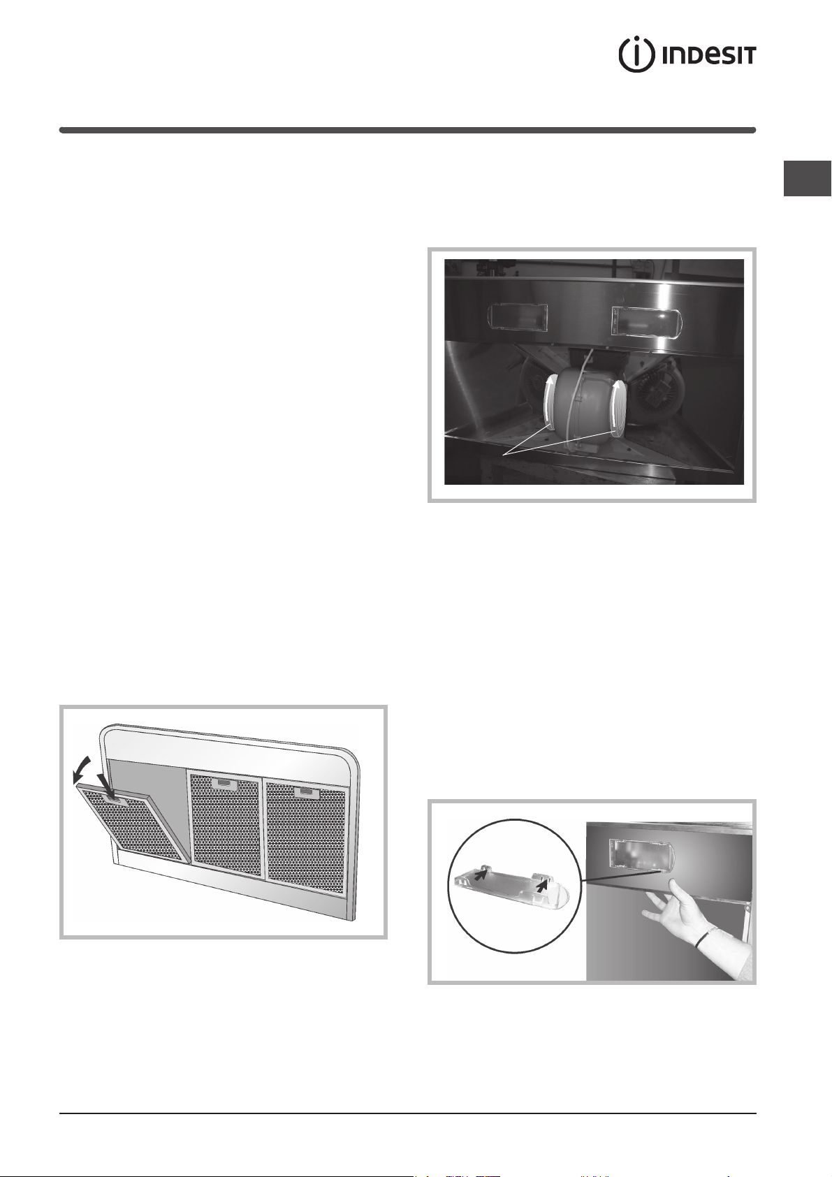
Replacing the lamps
Cleaning the grease filters
To remove the grease filters, push the catch near the
handle towards the inside and pull the filter
downwards.
Wash the filters by hand or in the dishwasher using
a neutral detergent. If they are washed
in the dishwasher, any loss of colour will
not jeopardise functioning of the filters in any way.
Pay particular ATTENTION when carrying out this
operation and remember to remove the voltage.
After having removed the grease filters, remove
the light fitting, operating manually from inside
the hood.
Apply light pressure to the mobile part of the 2
retainers and release it from the outside.
Unscrew the bulb and replace it with a bulb
of the same type.
Re-assemble the light fitting by pushing it into its
seat from the outside.
Clean the grease filters every 2 months on average
depending on how heavily the hood is used.
15
Precautions and tips
GB
General safety
! The distance between the supporting surface for
the cooking vessels on the hob and the lower part
of the hood must be at least 65 cm.
If the instructions for installation for the hob specify
a greater distance, this has to be taken into account.
! This appliance has such technical particulars
that it belongs to class II insulation, therefore
it must not be earthed.
! Avoid using materials which could cause spurts
of flame (flambées) near the appliance.
! When frying, take particular care to prevent oil
and grease from catching fire. Already used oil
is especially dangerous in this respect.
! Do not use uncovered electric grates.
! Do not place excessive weights above the hood.
Air vent
Should you install the ducting version, prepare the air
vent hole and duct.
In the Ducting version, to get optimal conditions the air
venting pipe should: be as short as possible, have the
lowest number of bends (max bende angle: 90°, be
made of material approved by local authorities
(according to the State), have its inner side as regular
and smooth as possible. It is moreover recommended
to avoid drastic changes of pipe cross section
(recommended diameter: 150 mm).
! The air collected must not be conveyed into a duct
used to blow off smokes from appliances fed with
an energy other than electricity (central heating
systems, thermosiphons, water-heaters, etc.).
! Comply with the official instructions provided by
the competent authorities in merit when installing
the disposal duct. In addition, exhaust air should
not be discharged into a wall cavity, unless
the cavity is designed for that purpose.
! The room must be well aerated in case a hood
and some other heat equipment fed with an energy
other than electricity (gas, oil, coal heaters, etc)
operate at the same time. In fact the ducting hood,
disposing of air, could create a vacuum in the room.
The vacuum should not exceed 0,04mbar.
This prevents the gas exhausted by the heat source
from being intaken again. It is therefore advisable
to ensure the room contains air taps able to ensure
a steady flow of fresh air.
Disposal
The European Directive 2002/96/EC on Waste
Electrical and Electronic Equipment (WEEE), requires
that old household electrical appliances must
not be disposed of in the normal unsorted municipal
waste stream.
Old appliances must be collected separately in order
to optimise the recovery and recycling of the materials
they contain and reduce the impact on human health
and the environment.
The crossed out “wheeled bin” symbol on the product
reminds you of your obligation, that when you dispose
of the appliance it must be separately collected.
Consumers should contact their local authority or
retailer for information concerning the correct disposal
of their old appliance.
16
Betriebsanleitung
ABZUGSHAUBE
I
Italiano, 1
F
Français, 25
NL
Nederlands, 49
H562 IX
H562 WH
H562 BK
H572 IX
H592 IX
GB
English, 9
E
Español, 33
D
Deutsch, 17
P
Portoguês, 41
Zusammenfassung
D
Installation, 18-19
Montage
Technische Informationen, 20
Elektroanschluss
Technische Daten
Beschreibung, 21
Umluftversion
Abluftversion
Betrieb, 22
Bedienung
Wartung, 23
Reinigung der Abzugshaube
Reinigung der Fettfilter
Austausch der Kohlefilter
Austausch der Lampen
Vorsichtsmaßnahmen und Hinweise, 24
Allgemeine Sicherheit
Abführung der Abluft
Entsorgung
17
 Loading...