

Page 1
GBD641EIX
GB641X
GX641RX
GX751RTX
English
Operating Instructions
HOB
Contents
Operating Instructions,1
Warnings,2
Description of the appliance,3
Installation,4
Start-up and use,9
Precautions and tips,10
Maintenance and care,10
Troubleshooting,11
Product Guarantee and Repair Information,12
Page 2
GB
Warnings
WARNING: The appliance and its accessible parts
become hot during use. Care should be taken to
avoid touching heating elements. Children less than 8
years of age shall be kept away unless continuously
supervised. This appliance can be used by children
aged from 8 years and above and persons with
reduced physical, sensory or mental capabilities or
lack of experience and knowledge if they have been
given supervision or instruction concerning use of the
appliance in a safe way and understand the hazards
involved. Children shall not play with the appliance.
Cleaning and user maintenance shall not be made
by children without supervision.
WARNING: Unattended cooking on a hob with fat or
oil can be dangerous and may result in re. NEVER
try to extinguish a re with water, but switch off the
appliance and then cover ame e.g. with a lid or a
re blanket.
WARNING: Danger of re: do not store items on the
cooking surfaces.
Never use steam cleaners or pressure cleaners on
the appliance.
Remove any liquid from the lid before opening it. Do
not close the glass cover (if present) when the gas
burners or electric hotplates are still hot.
The appliance is not intended to be operated by
means of an external timer or separate remote
control system.
CAUTION: the use of inappropriate hob guards can
cause accidents.
CAUTION: In case of hotplate glass breakage:
- shut immediately off all burners and any electrical
heating element and isolate the appliance from the
power supply
- do not touch the appliance surface.
2
Page 3
Description of the appliance
1
1
2
2
3
3
5
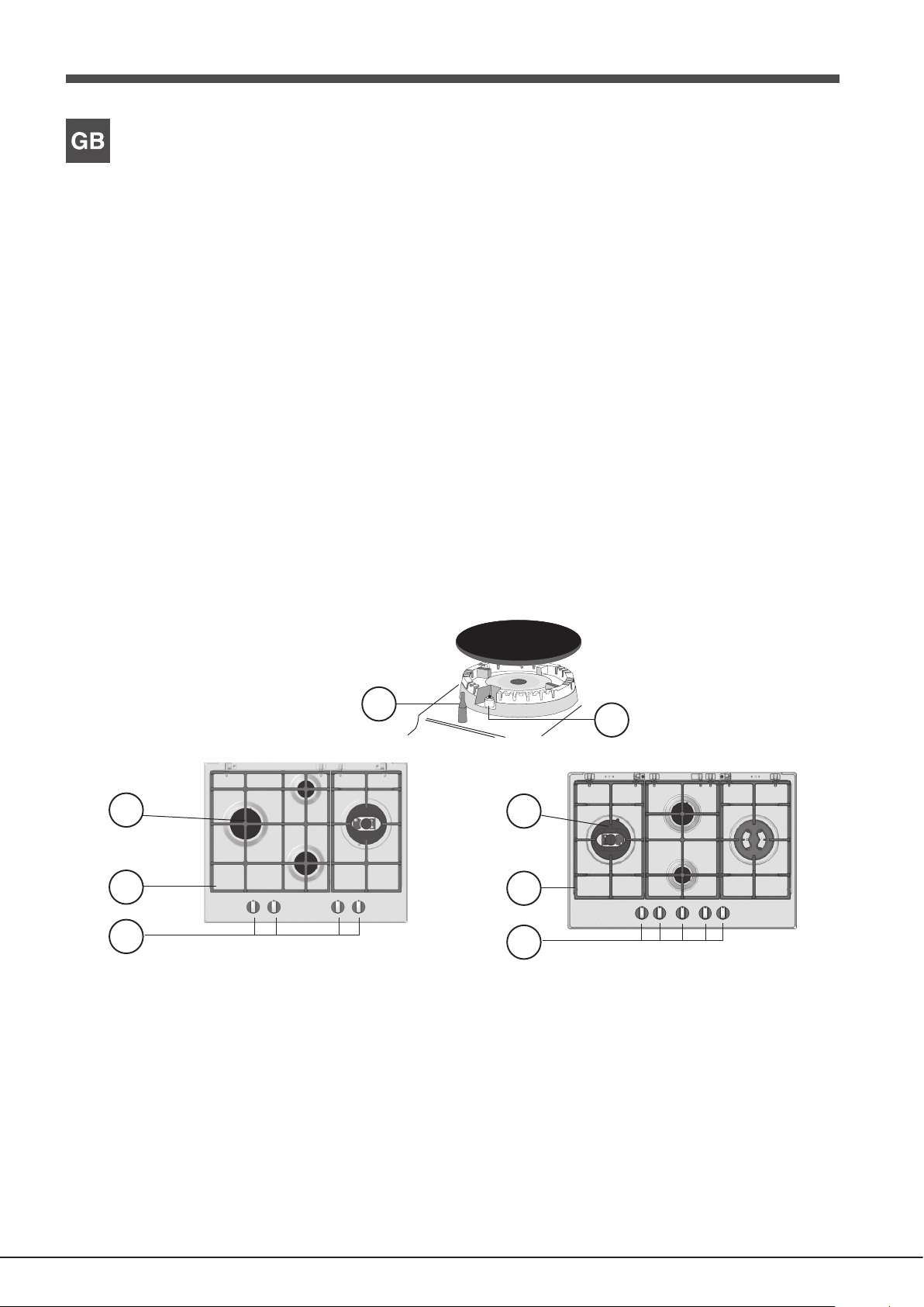
Overall view
1. Support Grid for COOKWARE
2. GAS BURNERS
3. Control Knobs for GAS BURNERS
4. Ignition for GAS BURNERS
5. SAFETY DEVICES
• GAS BURNERS differ in size and power. Use the diameter of the cookware
to choose the most appropriate burner to cook with.
• Control Knobs for GAS BURNERS adjust the power or the size of the
ame.
• GAS BURNER IGNITION enables a specic burner to be lit automatically.
• SAFETY DEVICE stops the gas flow if the flame is accidentally
extinguished.
4
3
Page 4
Installation
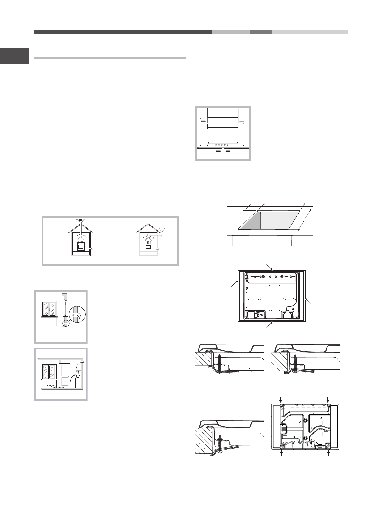
555 mm
55 mm
475 mm
GB
! Before operating your new appliance please read this instruction booklet
carefully. It contains important information for safe use, installation and care
of the appliance.
! Please keep these operating instructions for future reference. Pass them on
to possible new owners of the appliance.
Positioning
! Keep packaging material out of the reach of children. It can become a choking
or suffocation hazard (see Precautions and tips).
! The appliance must be installed by a qualied professional according to the
instructions provided. Incorrect installation may cause harm to people and
animals or may damage property.
! This unit may be installed and used only in permanently ventilated rooms
in accordance with current national regulations. The following requirements
must be observed:
• The room must be equipped with an air extraction system that expels
any combustion fumes. This may consist of a hood or an electric fan that
automatically starts each time the appliance is switched on.
Fitting the appliance
The following precautions must be taken when installing the hob:
• Kitchen cabinets adjacent to the appliance and taller than the top of the
hob must be at least 200 mm from the edge of the hob.
• Hoods must be installed according to their relative installation instruction
manuals and at a minimum distance of 650 mm from the hob (see gure).
• Place the wall cabinets adjacent to the hood at a minimum height of 420
mm from the hob (see gure).
If the hob is installed beneath a wall cabinet,
the latter must be situated at a minimum of
600mm min.
650mm min.
700 mm above the hob.
420mm min.
• The installation cavity should have the dimensions indicated in the gure.
Fastening hooks are provided, allowing you to fasten the hob to tops that
are between 20 and 40 mm thick. To ensure the hob is securely fastened
to the top, we recommend you use all the hooks provided.
In a chimney stack or branched flue.
(exclusively for cooking appliances)
Directly to
the Outside
• The room must also allow proper air circulation, as air is needed for
combustion to occur normally. The ow of air must not be less than 2 m3/h
per kW of installed power.
The air circulation system may take air directly
from the outside by means of a pipe with an
inner cross section of at least 100 cm
2
; the
opening must not be vulnerable to any type
Examples of
ventilation holes
for comburant air.
Adjacent
Room
A
Room to be
Vented
of blockages.
The system can also provide the air needed for
combustion indirectly, i.e. from adjacent rooms
tted with air circulation tubes as described
above. However, these rooms must not be
communal rooms, bedrooms or rooms that
may present a re hazard.
Enlarging the ventilation slot
between window and floor.
• Intensive and prolonged use of the appliance may necessitate
supplemental ventilation, e.g. opening a window or increasing the power
of the air intake system (if present).
• Liquid petroleum gas sinks to the oor as it is heavier than air. Therefore,
rooms containing LPG cylinders must also be equipped with vents to allow
gas to escape in the event of a leak. As a result LPG cylinders, whether
partially or completely full, must not be installed or stored in rooms or
storage areas that are below ground level (cellars, etc.). It is advisable to
keep only the cylinder being used in the room, positioned so that it is not
subject to heat produced by external sources (ovens, replaces, stoves,
etc. ) which could raise the temperature of the cylinder above 50°C.
• Before fastening the cooktop in place, position the seal (supplied) along
the perimeter of the countertop, as shown in the gure.
Hook fastening diagram
Hooking position for top H=20mm Hooking position for top H=30mm
Front
Hooking position for top H=40mm Back
! Use the hooks contained in the “accessory pack”.
4
Page 5
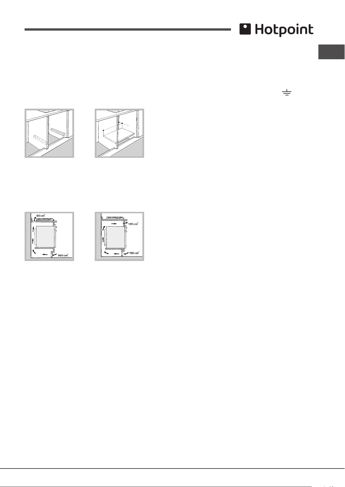
• Where the hob is not installed over a built-in oven, a wooden panel must
be installed as insulation. This must be placed at a minimum distance of
20 mm from the lower part of the hob.
Ventilation
To ensure adequate ventilation, the back panel of the cabinet must be
removed. It is advisable to install the oven so that it rests on two strips of
wood, or on a completely at surface with an opening of at least 45 x 560
mm (see diagrams).
45 mm.
560 mm.
! The hob can only be installed above built-in ovens with a cooling ventilation
system.
Where a hob is installed above an oven without a forced ventilation cooling
system, adequate ventilation must be provided inside the cabinet by means
of air holes through which air can pass (see gure).
! The wires in the mains lead are coloured in accordance with the following
code:
GB
Green & Yellow - Earth
Blue - Neutral
Brown - Live
As the colours of the wires in the mains lead may not correspond with the
coloured markings identifying the terminals in your plug, proceed as follows:
Connect the Green & Yellow wire to terminal marked “E” or or coloured
Green or Green & Yellow.
Connect the Brown wire to the terminal marked “L” or coloured Red or Brown.
Connect the Blue wire to the terminal marked “N” or coloured Black or Blue.
FAILURE TO OBSERVE THE ACCIDENT-PREVENTION REGULATIONS
RELIEVES THE MANUFACTURER OF ALL LIABILITY.
Replacing the cable
Use a rubber cable of the type H05RR-F with a suitable cross section 3 x
0.75 mm².
The yellow-green earth wire must be 2-3 cm longer than the other wires.
Gas connection
The appliance should be connected to the main gas supply or to a gas
cylinder in compliance with current national regulations. Before carrying out
the connection, make sure the cooker is compatible with the gas supply you
wish to use. If this is not the case, follow the instructions indicated in the
paragraph “Adapting to different types of gas.”
When using liquid gas from a cylinder, install a pressure regulator which
complies with current national regulations.
! Check that the pressure of the gas supply is consistent with the values indicated
in Table 1 (“Burner and nozzle specications”). This will ensure the safe operation
and longevity of your appliance while maintaining efcient energy consumption.
Connection with a rigid pipe (copper or steel)
! Connection to the gas system must be carried out in such a way as not to
Electrical connection
! THIS APPLIANCE MUST BE EARTHED.
The hob is designed to work with alternating current, the supply voltage and
frequency indicated on the rating plate (situated under the hob). Make sure
that the local supply voltage corresponds to the voltage indicated on the
place any strain of any kind on the appliance.
There is an adjustable L-shaped pipe tting on the appliance supply ramp
and this is tted with a seal in order to prevent leaks. The seal must always
be replaced after rotating the pipe tting (seal provided with appliance). The
gas supply pipe tting is a threaded 1/2 gas cylindrical male attachment.
rating plate.
Connecting a flexible jointless stainless steel pipe to a threaded
Connecting the supply cable to the mains electricity supply
For models supplied without a plug, t a standard plug suitable for the load
indicated on the rating plate, onto a cable and connect to a suitable socket.
To connect direct to the mains supply, a double pole switch with a contact
separation of at least 3mm suitable for the load and complying with current
attachment
The gas supply pipe tting is a threaded 1/2 gas cylindrical male attachment.
These pipes must be installed so that they are never longer than 2000 mm
when fully extended. Once connection has been carried out, make sure that
the exible metal pipe does not touch any moving parts and is not compressed.
standards and regulations must be tted between the appliance and the
mains supply outlet.
! Only use pipes and seals that comply with current national regulations.
The green-yellow earth wire must not be interrupted by the switch.
The supply cable must be positioned so that no part of it reaches a temperature
of 50°C above room temperature. For installation above a built-under
oven, the hob and the oven must be connected separately to the electricity
Checking the tightness of the connection
! When the installation process is complete, check the pipe ttings for leaks
using a soapy solution. Never use a ame.
supply, both for safetly reasons and for easy removal of the oven for repair,
maintenance etc.
DO NOT use adapters as they could cause overheating or burning.
Adapting to different types of gas
To adapt the hob to a different type of gas other than default type (indicated
on the rating plate at the base of the hob or on the packaging), the burner
Before connecting to the power supply, make sure that:
• the limiter switch and the domestic system can withstand the load from
the appliance (see rating plate).
nozzles should be replaced as follows:
1. Remove the hob grids and slide the burners off their seats.
2. Unscrew the nozzles using a 7 mm socket spanner, and replace them
• the supply system is efciently earthed according to standards and laws
in force.
• the socket or double-pole switch are easily accessible when the appliance
3. Reassemble the parts following the above procedure in the reverse order.
is installed.
with nozzles for the new type of gas (see table 1 “Burner and nozzle
characteristics”).
5
Page 6
4. Once this procedure is nished, replace the old rating sticker with one
GB
indicating the new type of gas used. Sticker are available from any of our
Service Centres.
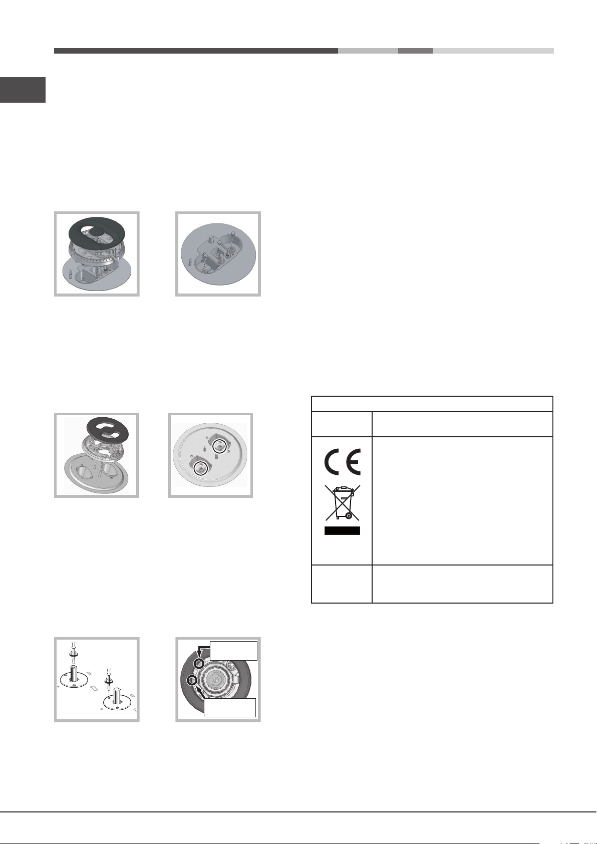
Replacing the nozzles on separate “double ame “ burners
1. Remove the grids and slide the burners from their housings. The burner
consists of 2 separate parts (see gure);
2. Unscrew the burers with a 7 mm wrench spanner. The internal burner
has a nozzle, the external burner has two (of the same size). Replace
the nozzle with models suited to the new type of gas (see table 1).
3. Replace all the components by repeating the steps in reverse order.
Replacing the Triple ring burner nozzles
1. Remove the pan supports and lift the burners out of their housing. The
burner consists of two separate parts (see pictures).
2. Unscrew the nozzles using a 7 mm socket spanner. Replace the nozzles
with models that are congured for use with the new type of gas (see Table
1). The two nozzles have the same hole diameter.
3. Replace all the components by completing the above operations in reverse
order.
• Adjusting the burners’ primary air
Does not require adjusting.
• Setting the burners to minimum
1. Turn the tap to the low ame position;
2. Remove the knob and adjust the adjustment screw, which is positioned
in or next to the tap pin, until the ame is small but steady.
! In the event of single-control DRDA (DCDR) burners, adjustment can be
performed by intervening on the 2 screws located near the tap pin (see picture).
4. Some appliances have a safety device (thermocouple) tted. If the device
fails to work when the burners are set to the low ame setting, increase
this low ame setting using the adjusting screw.
5. Once the adjustment has been made, replace the seals on the by-passes
using sealing wax or a similar substance.
6. In the event of discrete-adjustment knobs with LED visualisation, turn the
knob to the minimum power setting them remove it and intervene on the
adjustment screw located near the tap pin.
7. Minimum setting adjustment of the DRDA (DCDR) burner with discrete
adjustment and LED visualisation:
• To adjust the outer ring, turn the knob anti-clockwise to the minimum
power position.
• To adjust the minimum power setting of the inner ring, turn the knob
clockwise to the minimum power position.
• Remove the knob and intervene on the adjustment screw located near
the tap pin.
! If the appliance is connected to liquid gas, the regulation screw must be
fastened as tightly as possible.
! Once this procedure is nished, replace the old rating sticker with one
indicating the new type of gas used. Stickers are available from any of our
Service Centres.
! Should the gas pressure used be different (or vary slightly) from the
recommended pressure, a suitable pressure regulator must be tted to the
inlet pipe (in order to comply with current national regulations).
DATA PLATE
Electrical
connections
ECODESIGN
see data plate
This appliance conforms to the following
European Economic Community directives:
- 2006/95/EC dated 12/12/06 (Low Voltage)
and subsequent amendments
- 2004/108/EC dated 15/12/04
(Electromagnetic Compatibility) and
subsequent amendments
- 93/68/EEC dated 22/07/93 and subsequent
amendments.
- 2009/142/EC dated 30/11/06 (Gas) and
subsequent amendments
- 2012/19/EU and subsequent amendments.
EU Regulation no. 66/2014 implementing
Directive 2009/125/EC.
standard EN 30-2-1
Total DRDA
(DCDR) burner
adjustment
Inner DRDA (DCDR)
burner adjustment
3. Having adjusted the ame to the required low setting, while the burner is
alight, quickly change the position of the knob from minimum to maximum
and vice versa several times, checking that the ame does not go out.
6
Page 7
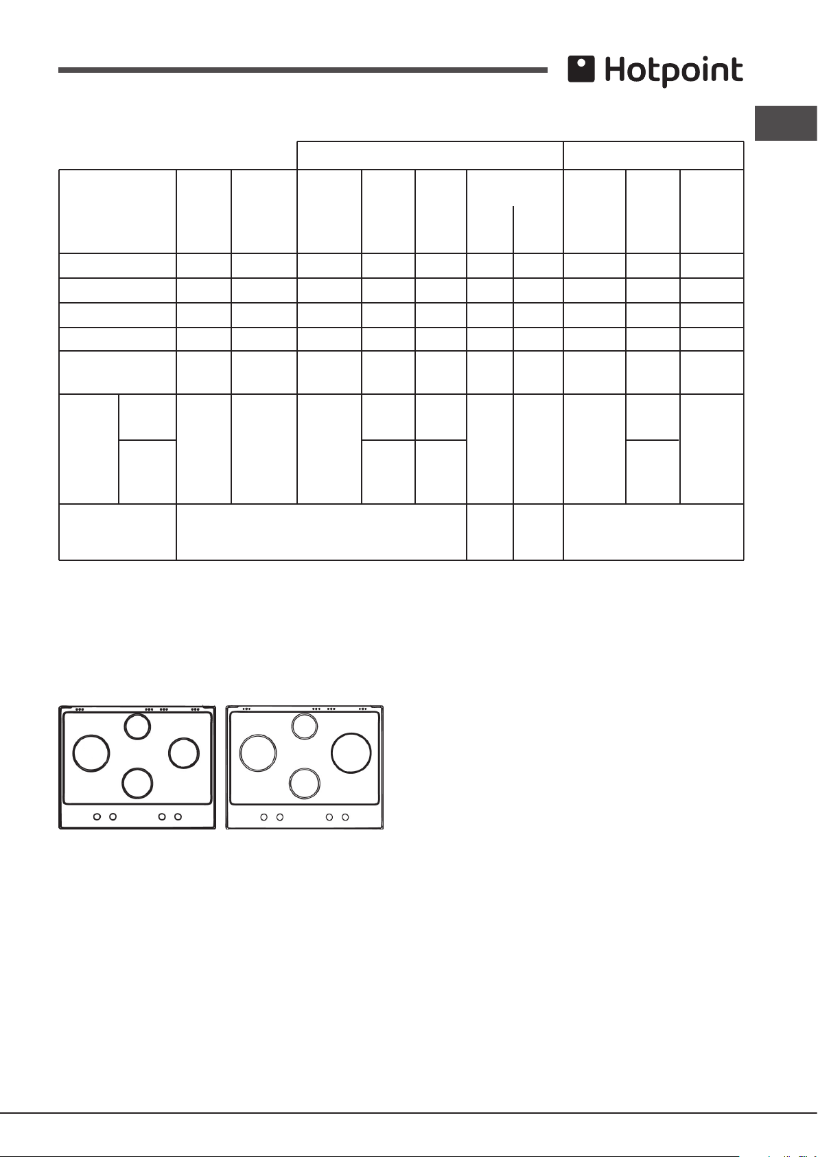
Table 1 Liquid Gas Natural Gas
Burner and nozzle specifications (for 65 cm versions only)
Natural P. C.S. = 37.78 MJ/m³
GBD641EIX
Burner Diameter Thermal Thermal By-pass Nozzle Flow* Thermal Nozzle Flow*
power power 1/100 1/100 (g/h) power 1/100 (l/h)
kW kW kW
(p.c.s.*) (p.c.s.*) (p.c.s.*)
(mm) Reduced Nominal (mm) (mm) *** ** Nominal (mm)
Fast (R)
100
0.70
3.00
39
86
218
214
3.00
132(H3)
286
GB
Reduced Fast (RR)
Semi Fast (S)
Auxiliary (A)
Double flame
(DCDR internal) (1)
Double
flame (1)
Supply pressures Nominal (mbar)
(1) For single-control DRDA (DCDR) burner only
* At 15°C and 1013,25 mbar - dry gas
** Propane P. C.S. = 50.37 MJ/Kg
*** Butane P. C.S. = 49.47 MJ/Kg
(DCDR
internal)
(DCDR
external
2 nozzle)
100
75
55
36 0.30 0.90 29 44 65 64 0.90 74 86
130 1.50 3.60
0.70
0.40
0.40
Minimum (mbar)
Maximum (mbar)
2.60
1.65
1.00
39
28
28
29 44
57 60x2 94x2
80
64
50
189
120
73
262 257 3.60
28-30
20
35
186
118
71
37
25
45
2.60
1.65
1.00
122(H3)
96(Z)
79(6)
74
20
17
25
248
157
95
343
R
GB 641 X
A
S
A
S
RR
DC
S
GX 641 R X
7
Page 8
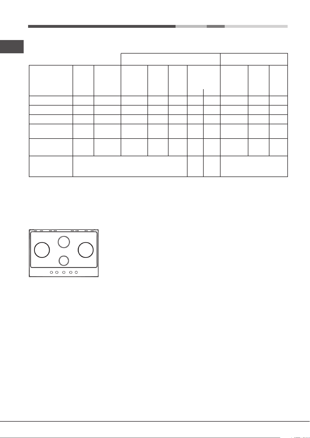
GB
GX 751 R T X
Burner and nozzle specifications (for 75 cm versions only)
(2) For dual-control DRD
*
**
***
Table 1 Liquid Gas Natural Gas
Semi Fast (S)
Auxiliary (A)
Triple Crown (TC
Double Flame
(DCDR Internal) (2)
Double Flame
(DCDR External)
2 nozzle (2)
Supply pressures
At 15°C and 1013,25 mbar - dry gas
Propane P.C.S. = 50.37 MJ/Kg
Butane P. C.S. = 49.47 MJ/Kg
Natural P. C.S. = 37.78 MJ/m³
Diameter
(mm)
75
55
130
36
130
A (DCDR) burner only
Thermal
power
kW (p.c.s.*)
Reduced
0.40
0.40
1.50
0.40
1.50
Thermal
power
kW (p.c.s.*)
Nominal
1.65
1.00
3.30
0.90
4.10
Nominal (mbar)
Minimum (mbar)
Maximum (mbar)
By-pass
1/100
(mm)
28
28
61
28
61
Nozzle
1/100
(mm)
64
50
65x2
44
70x2
Flow* (g/h) Flow*
*****
120
240
298
28-30
73
65
20
35
118
71
236
64
293
37
25
45
Thermal
power
kW (p.c.s.*)
Nominal
1.65
1.00
3.60
0.90
4.10
Nozzle
1/100
(mm)
96(Z)
79(6)
103x2
74
110x2
20
17
25
(l/h)
157
95
343
86
390
S
DC TC
A
8
Page 9
Start-up and use
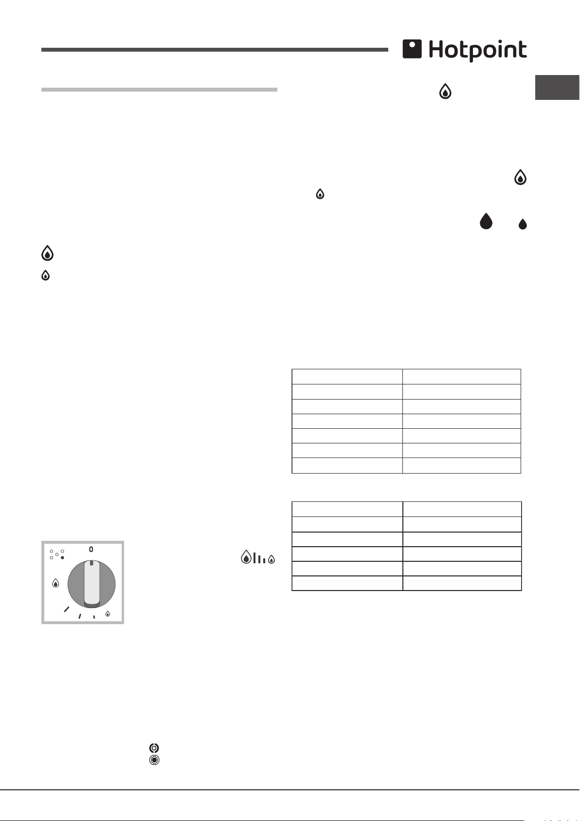
To activate any one of the two rings, press the corresponding knob and turn
it anti-clockwise to the maximum power setting .
! The position of the corresponding gas burner is shown on every knob.
In order to use the double-ame burner to its full potential, avoid
simultaneously setting the inner ring to minimum power and the outer
Gas cooker hobs are equipped with discrete power adjustment that allows
ring to maximum power.
for accurately adjusting the ame to 5 different power levels. Thanks to this
system, gas hobs are also capable of guaranteeing the same cooking results
for each recipe, as the optimal power level for the desired type of cooking can
Single control:
The rings comprising the burner are activated through a single control knob.
be identied in an easier, more accurate way.
To simultaneously turn on both rings, position the knob on the symbol
Gas burners
(max) - (min) then press and turn the knob anti-clockwise.
Each burner can be adjusted to one of the following settings using the
corresponding control knob:
To turn on the inner ring only, position the knob on the symbol (max ) -
● Off
(min) then press and turn the knob clockwise.
(to switch modes, it is necessary to switch off the burner).
Maximum
Minimum
To switch off the burner, press and turn the knob clockwise until it stops (when
it reaches the “●” position).
GB
To light one of the burners, hold a lit match or lighter near the burner and, at
the same time, press down and turn the corresponding knob anti-clockwise
to the maximum setting.
Since the burner is tted with a safety device, the knob should be pressed
for approximately 2-3 seconds to allow the automatic device keeping the
ame alight to heat up.
When using models with an ignition button, light the desired burner pressing
down the corresponding knob as far as possible and turning it anticlockwise
towards the maximum setting.
! If a ame is accidentally extinguished, turn off the control knob and wait for
at least 1 minute before trying to relight it.
To switch off the burner, turn the knob in a clockwise direction until it stops
(when reaches the “●” position).
Discrete ame adjustment
The selected burner can be adjusted - by means of the knob - to 5 different
power levels. To shift between levels, simply turn the knob towards the
desired power level.
A click signals the passage from one power level to the other.
The selected power level is indicated by the
corresponding symbol (symbols )
and, on hobs equipped with a display, by the
LEDs that turn on (5 = max. power; 1 = min.
power). The system guarantees accurate ame
adjustment and uniform cooking results by
facilitating selection of the desired power level.
The “double-ame” burner
This gas burner consists of two concentric ame rings that can operate jointly
or independently (in case of dual-control only).
As the burner is tted with a safety device, the knob should be pressed
down for approximately 2-3 seconds until the device keeping the ame
automatically alight heats up.
Dual control:
Each ring comprising the burner has its own control knob:
The knob marked with the symbol controls the outer ring.
The knob marked with the symbol controls the inner ring.
Practical advice on using the burners
To ensure the burners operate efciently:
• Use appropriate cookware for each burner (see table) so that the ames
do not extend beyond the bottom of the cookware.
• Always use cookware with a at base and a cover.
• When the contents of the pan reach boiling point, turn the knob to minimum.
Burner
Rapid (R)
Reduced Rapid (RR)
Semi Rapid (S)
Auxiliary (A)
Double Flame (DCDR internal)
Double Flame (DCDR external)
Pans to be used on 65 cm hobs
Burner Ø Cookware diameter (cm)
Semi Rapid (S)
Auxiliary (A)
Triple Crown (TC)
Double Flame (DCDR internal)
Double Flame (DCDR external)
Pans to be used on 75 cm hobs
! On the models supplied with a reducer shelf, remember that this should be
used only for the Double ame internal (DCDR internal) burner when you use
casserole dishes with a diameter under 12 cm.
To identify the type of burner, refer to the designs in the section entitled,
“Burner and Nozzle Specications”.
• For maximum stability, always make sure that the pan supports are
correctly tted and that each pan is placed centrally over the burner.
• Pan handles should be positioned in line with one of the support bars on
the pan support grid.
• Pan handle should be positioned so not to protrude beyond the front edge
of the hob.
Ø Cookware diameter (cm)
24 - 26
24 - 26
16 - 20
10 - 14
10 - 14
24 - 26
16 - 20
10 - 14
24 - 26
10 - 14
26 - 28
9
Page 10
GB
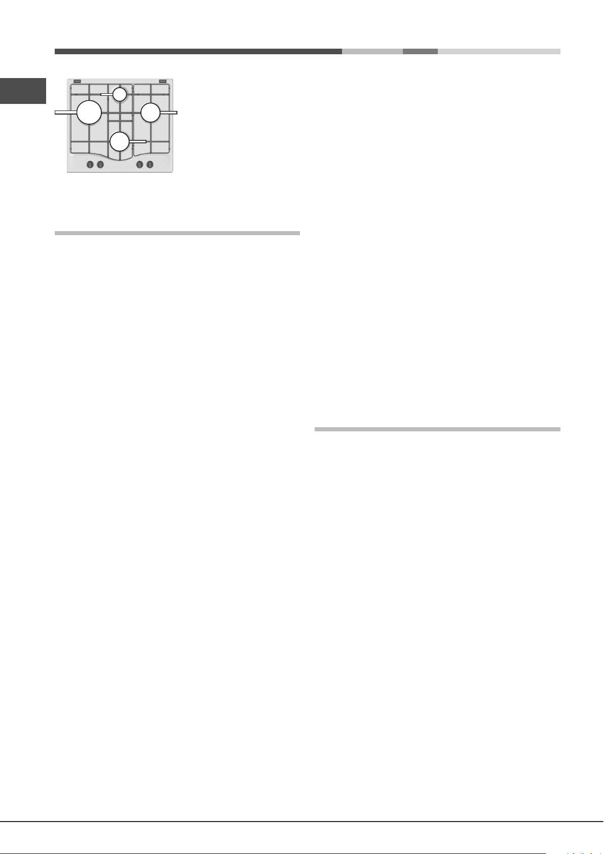
The more variable aspect in terms
of pan stability can often be the pan
itself, (or the positioning of that pan
during use). Well balanced pans,
with flat bases that are placed
centrally over the burner, with the
pan handles aligned with one of the
support ngers obviously offer the
greatest stability.
Precautions and tips
! This appliance has been designed and manufactured in compliance with
international safety standards. The following warnings are provided for safety
reasons and must be read carefully.
• Do not let children play with the appliance.
• The appliance is not intended to be operated by means of an external
timer or separate remote-control system.
Disposal
• When disposing of packaging material: observe local legislation so that
the packaging may be reused.
• The European Directive 2012/19/EU on Waste Electrical and
Electronic Equipment (WEEE), requires that old household electrical
appliances must not be disposed of in the normal unsorted municipal
waste stream. Old appliances must be collected separately in order
to optimise the recovery and recycling of the materials they contain
and reduce the impact on human health and the environment.
The crossed out “wheeled bin” symbol on the product reminds you of your
obligation, that when you dispose of the appliance it must be separately
collected.
Consumers should contact their local authority or retailer for information
concerning the correct disposal of their old appliance.
General safety
• This is a class 3 built-in appliance.
• Gas appliances require regular air exchange to maintain efcient
operation. When installing the hob, follow the instructions provided
in the paragraph on “Positioning” the appliance.
• These instructions are only valid for the countries whose symbols
appear in the manual and on the serial number plate.
• The appliance was designed for domestic use inside the home and is
not intended for commercial or industrial use.
• The appliance must not be installed outdoors, even in covered areas. It is
extremely dangerous to leave the appliance exposed to rain and storms.
• Do not touch the appliance with bare feet or with wet or damp hands and
feet.
• The appliance must be used by adults only for the preparation of food,
in accordance with the instructions outlined in this booklet. Any other
use of the appliance (e.g. for heating the room) constitutes improper
use and is dangerous. The manufacturer may not be held liable for
any damage resulting from improper, incorrect and unreasonable
use of the appliance.
• Ensure that the power supply cables of other electrical appliances do not
come into contact with the hot parts of the oven.
• The openings used for ventilation and dispersion of heat must never be
covered.
• Always make sure the knobs are in the “●”/“○” position when the appliance
is not in use.
• When unplugging the appliance always pull the plug from the mains socket,
do not pull on the cable.
• Never carry out any cleaning or maintenance work without having detached
the plug from the mains.
• In case of malfunction, under no circumstances should you attempt to repair
the appliance yourself. Repairs carried out by inexperienced persons may
cause injury or further malfunctioning of the appliance. Contact a Service
Centre (see Assistance).
• Do not use unstable or deformed pans.
• Do not close the glass cover (if present) when the gas burners or electric
hotplates are still hot.
• Do not leave the electric hotplate switched on without a pan placed on it.
• The appliance should not be operated by people (including children)
with reduced physical, sensory or mental capacities, by inexperienced
individuals or by anyone who is not familiar with the product. These
individuals should, at the very least, be supervised by someone who
assumes responsibility for their safety or receive preliminary instructions
relating to the operation of the appliance.
Respecting and conserving the environment
• Cook your food in closed pots or pans with well-tting lids and use as little
water as possible. Cooking with the lid off will greatly increase energy
consumption.
• Use purely at pots and pans.
• If you are cooking something that takes a long time, it’s worth using a
pressure cooker, which is twice as fast and saves a third of the energy.
Maintenance and care
Switching the appliance off
Disconnect your appliance from the electricity supply before carrying out
any work on it.
Cleaning the appliance
! Do not use abrasive or corrosive detergents such as stain removers, anti-rust
products, powder detergents or sponges with abrasive surfaces: these may
scratch the surface beyond repair.
! Never use steam cleaners or pressure cleaners on the appliance.
• It is usually enough to wash the hob with a damp sponge and dry it with
absorbent kitchen roll.
• The removable parts of the burners should be washed frequently with
warm water and soap and any burnt-on substances removed.
• For hobs which ligth automatically, the terminal part of the electronic instant
lighting devices should be cleaned frequently and the gas outlet holes
should be checked for blockages.
• Stainless steel can be marked by hard water that has been left on the
surface for a long time, or by aggressive detergents containing phosphorus.
After cleaning, rinse and dry any remaining drops of water.
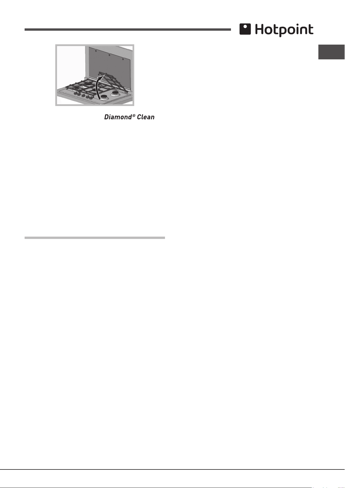
! It is not necessary to remove the pan supports in order to clean the hob
surface. Thanks to the support system, simply lift and hold the pan supports
or rotate them until they rest against a rear support.
Do not place the hot grids on top of the glass cover (if applicable),
otherwise the rubber plugs on the glass may be damaged.
10
Page 11
Clening tips for the hotplates with logo
To remove all types of stains just wipe with a smooth cloth, wet with hot water.
For stronger stains, we recommend the use of common detergent for dishes,
with a cloth dampened with hot water, to ensure a perfect cleaning result.
! Never use aggressive detergents or coarse sponges because they
can cause irreversible damage to the special protection treatment with
formation of irremovable stains and halos.
Gas tap maintenance
Over time, the taps may become jammed or difcult to turn. If this happens,
the tap must be replaced.
! This procedure must be performed by a qualied technician authorised
by the manufacturer.
GB
Troubleshooting
It may happen that the appliance does not function properly or at all. Before
calling the service centre for assistance, check if anything can be done. First,
check to see that there are no interruptions in the gas and electrical supplies,
and, in particular, that the gas valves for the mains are open.
The burner does not light or the ame is not even around the burner.
Check whether:
• The gas holes on the burner are clogged.
• All the movable parts that make up the burner are mounted correctly.
• There are draughts near the appliance.
The ame dies in models with a safety device.
Check to make sure that:
• You pressed the knob all the way in.
• You keep the knob pressed in long enough to activate the safety device.
• The gas holes are not blocked in the area corresponding to the safety
device.
The burner does not remain lit when set to minimum.
Check to make sure that:
• The gas holes are not blocked.
• There are no draughts near the appliance.
• The minimum setting has been adjusted properly.
The cookware is unstable.
Check to make sure that:
• The bottom of the cookware is perfectly at.
• The cookware is positioned correctly at the centre of the burner.
• The pan support grids have been positioned correctly.
11
Page 12
Product Guarantee and Repair Information
Guarantee
12 Months Parts and Labour Guarantee
Your appliance has benefit of our manufacturer’s guarantee, which covers
t
T
to
discretion, either repair or replace the appliance at no cost
This guarantee is subject to the following conditions
with our operating and maintenance instructions
rating plate.
-
otherwise interfered with by any person not authorised by us
-
become our propert
-
The guarantee does not cover
or as a result of improper installation
are not limited to:plugs,cables,batteries,light bulbs,fluorescent tubes an
starters, covers and filters.
- Replacement of any removable parts made of glass or plastic.
THIS
U
e
Indesit Company S.p.A.
V
60044 Fabriano (AN)
www.hotpoint.co.uk
GB
Recycling and Disposal Information
As part of Hotpoint’s continued commitment to helping the environment,
Hotpoint reserves the right to use quality, recycled components to keep down
he cost of breakdown repairs for twelve months from the date of purchase.
his gives you the reassurance that if, within that time, your appliance is proven
be defective because of either workmanship or materials, we will, at our
to you:
:
The appliance has been installed and operated correctly and in accordance
.
The appliance is used only on the electricity or gas supply printed on the
The appliance has been used for normal domestic purposes only.
The appliance has not been altered, serviced, maintained, dismantled, or
.
Any repair work must be undertaken by us or our appointed agent.
Any parts removed during repair work or any appliance that is replaced
y.
The appliance is used in the United Kingdom or Republic of Ireland.
customer costs and minimise material wastage.
Please dispose of packaging and old appliances carefully. To minimise the
risk of injury to children, remove the door, plug, and cut the mains cable off
flush with the appliance.Dispose of these parts separately to ensure that th
appliance can no longer be plugged into mains socket, and the door cannot
be locked shut.
Repairs and After Sales
For product help and advice, repairs, spare parts or accessories, we’re here
to help.
For local repair engineers - 03448 111 606
ROI - 0818 313 413
UK standard local rate applies
ROI local Irish rate applies
195130967.01
08/2015 - XEROX FABRIANO
:
Damage resulting from transportation, improper use, neglect or interference
.
Replacement of any consumable item or accessory. These include but
GUARANTEE WILL NOT APPLY IF THE APPLIANCE HAS BEEN
SED IN COMMERCIAL OR NON-DOMESTIC PREMISES.
For Parts and Accessories visit:
parts.hotpoint.co.uk/shop
Please remember to register your appliance at www.hotpointservice.co.uk
d
to activate your 10 year parts guarantee.
Please note, our advisors will require the following information:
Model number:
Serial number:
iale Aristide Merloni,47
12
 Loading...