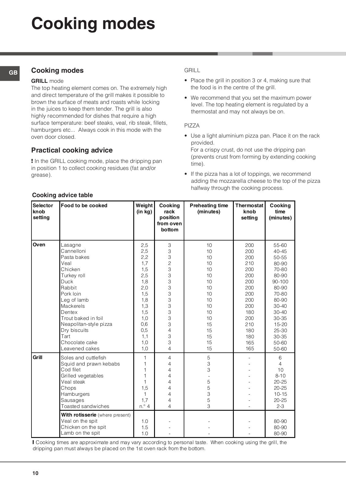
How it Works
Log In / Sign Up
Buy Points
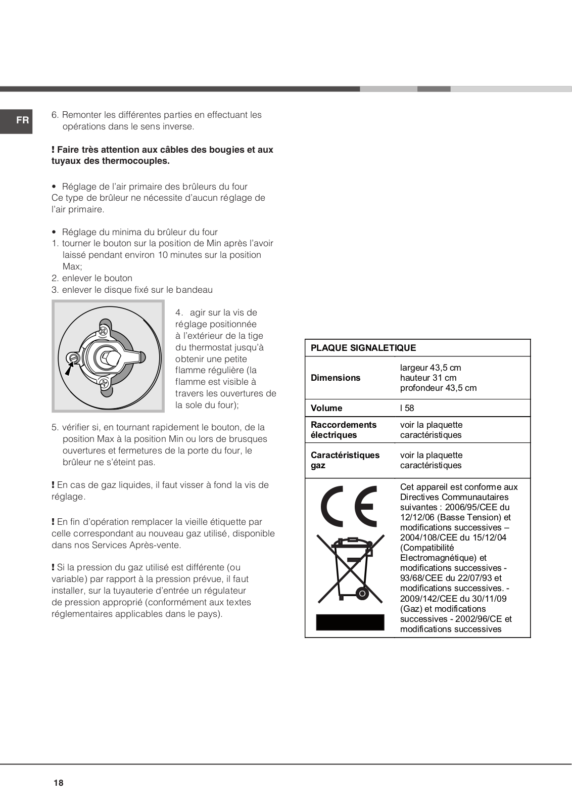
How it Works
FAQ
Contact Us
Questions and Suggestions
Users
Hotpoint
Loading...
F
FK1039ELP 0 X/HA
FK1039ENP 0 X/HA
FK103ENC
FK103EN HA X
FK103ENP20
FK1047LP20
FK104P20
FK 637J X /HA S
FK63C
FK 63C /HA S
FK 63 C X-HA
FK 63C X /HA S
FK 63J X /HA S
FK 63 X /HA S
FK 736JC /HA S
FK 736 J C X/HA
FK 736JC X /HA S
FK 737 C X AUS
FK 83 0 X/HA S
FK 831 J X/HA
FK 832 J X/HA
FK 837 J X/HA
FK 83 X
FK 83 X/HA
FK 83 X S
FK 891E P. 20 X/HA
FK 892EJ P 0 X/HA
FK 897 E 0 X/HA
FK897E.1 J P.20 X/HA
FK 897 E X/HA S
FK 898E C 0 X/HA
FK 898E C.20 X/HA
FK 898E P X AUS S
FK 89E 0 X/HA
FK 89 E .20 X/HA S
FK89EC
FK 89E C 0 X/HA
FK 89E E.20 X/HA
FK89EL .20 X/HA
FK 89 EL .20 X/HA S
FK 89EL P.20 X/HA S
2
FK 89ELS .20 X/HA
FK89EP .20 X/HA
2
FK 89 E P.20 X/HA S
2
FK 89 ES P.20 X/HA
FK 89E X
FK 89E X S
FK 89 P 0 BK/HA S
FK 89P /HA S
FK 89 P X-HA
FK 89 P X/HA S
FK 932 C X/HA
FK 932 C X/HA S
FK 939J X/HA
FK 93J X/HA
FK 992EJ 1 X/HA
FK 996E C.20 X/HA S
FK 996E C X
FK 996E C X S
FK 99EJ .20 X/HA
FK 99 EJ .20 X/HA S
FK G X /HA S
2
FK G X S
FKQ 61
FKQ 616 J
FKQ 616J /HA S
FKQ 61 /HA S
FKQ63C
FKQ 63C /HA S
FKQ 73C /HA S
FKQ 831
FKQ 831 0 BK/HA
FKQ 898E C 0
FKQ 898E C.20
FKQ 89E.20
FKQ 89 E.20 /HA
FKQ 89EL .20
FKQ 89 EL.20/HA S
FKQ 89 ELP.20/HA S
FKQ 89E P
FKQ 89E P 0
FKQ 89 E P /HA S
FKQ 992EJ .20
FKQ 992 EJ.20 /HA S
FKQ 99E C
FKS 610 /HA S
FKS 610 X/HA
FKS 610 X/HA S
FKS 89 EL .20 X/HA S
FM53F ALU
FMD 1043B FR
FMD 722MB EU
FMD 723MB EU
2
FMD 763 SK
FMD 763 SK.C
FMD 823MB EU.C
FMD 8247 B EU
FMD 843B EU
FMD 863 SK
FMD 923BS EU.C
Loading...
Loading...
Nothing found
FK G X S
User Manual
72 pgs
5.57 Mb
0
Table of contents
Loading...
Hotpoint FK G X S User Manual
...
Hotpoint User Manual
Download
Specifications and Main Features
Frequently Asked Questions
User Manual
Download
Loading...
+
hidden pages
Unhide
You need points to download manuals.
1 point = 1 manual.
You can buy points or you can get point for every manual you upload.
Buy points
Upload your manuals
 Loading...