How it Works
Log In / Sign Up
Buy Points
How it Works
FAQ
Contact Us
Questions and Suggestions
Users
Hotpoint
Loading...
F
FH103P
FH103PIX
FH 21 IX
FH 21 IX/HA
FH 21 IX/HA S
2
FH 23 C
FH 23 C IX/HA
FH 51 /HA
FH 51 /HA S
FH51IX
FH 51 IX CN
FH 51 IX CN S
FH 51 IX /HA
FH 51 IX /HA S
FH 52 IX AG
FH53
FH 531 IX S
FH 532 IX/HA
FH 532 IX/HA S
FH 538
FH 538 0
FH53HAIX
FH 53 IX-HA
FH 53 IX/HA S
FH 62 IX/HA
FH 637 0
FH 832 J IX/HA PL
FH83CHABK
FH 83 C HA IX
2
FH83CHAWH
2
FH83CIXHA
FH 83C WHHA
FH 83 IX AG
FH 83 IX AG S
FH 83 IX/HA S
FH89
FH 891 P /HA
FH 891 P IX/HA
FH 891 P IX/HA S
FH 899 C XA/HA
FH 899 C XA/HA S
FH 899 XA/HA
FH89P
FH 89 P /HA
FH 89 P /HA S
FH89PHASBK
FH89PHA WH
FH 89 P IX/HA
FH 939 IX
FH 939 IX S
FH 997 C IX/HA
FH 99 C IX/HA S
FH 99 IX
FH99P
FH 99 P /HA
FH 99 P /HA S
FH99PIX
FH 99 P IX/HA
FH 99 P IX/HA S
FH99PM
FH 99 P M /HA S
FH 99 P M IX/HA
FH 99 P M IX/HA S
FH 99 P M IX S
FHB 51 /HA S
FHB 51 IX/HA
FHB 51 IX/HA S
FH G
FH G IX
FH G IX AG
FH G IX/HA
FH G IX/HA S
FH G IX S
FHM 53 C IX/HA
FHR 540 /HA S
FHR 640
FHR 648
FHS 210 IX/HA S
FHS 21 IX
FHS 21 IX/HA
FHS 21 IX/HA S
FHS 21 IX S
FHS 230 /HA
FHS 230 IX HA
FHS 516 IX/HA
FHS 516 IX/HA S
FHS 51 /HA
FHS 51 /HA S
FHS 51 IX/HA
2
FHS 51 IX/HA S
2
FHS 51 IX S
FHS 536 IX/HA
FHS 536 IX/HA S
FHS 538 IX/HA
FHS 538 IX/HA S
FHS 53 C IX/HA
FHS 53 C IX/HA S
FHS 53 IX/HA S
FHS 89 P IX/HA
FHS 89 P M IX/HA S
2
Loading...
Loading...
Nothing found
FH G IX
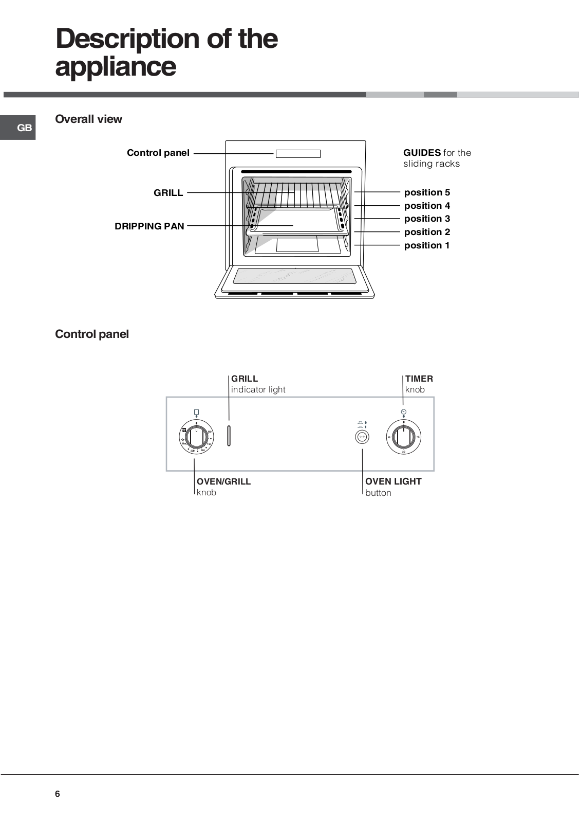
User Manual
56 pgs
2.88 Mb
0
Table of contents
Loading...
Hotpoint FH G IX User Manual
...
Hotpoint User Manual
Download
Specifications and Main Features
Frequently Asked Questions
User Manual
Download
Loading...
+
39
hidden pages
Unhide
You need points to download manuals.
1 point = 1 manual.
You can buy points or you can get point for every manual you upload.
Buy points
Upload your manuals
 Loading...