


FF7190EX

Operating Instructions
REFRIGERATOR/FREEZER COMBINATION
GB
English
FF7190EP
FF7190EX
FF7190AEX
FF7190AEP
Contents
Installation, 2
Positioning and connection
Description of the appliance, 3-4
Control panel
Overall view
Accessories, 5
Start-up and use, 6-7
Starting the appliance
Chiller system
Using the refrigerator to its full potential
Using the freezer to its full potential
Maintenance and care, 8
Switching the appliance off
Cleaning the appliance
Avoiding mould and unpleasant odours
Replacing the light bulb
Precautions and tips, 9
General safety
Disposal
Respecting and conserving the environment
GB
GB
Troubleshooting, 10
Guarantee, 11
After Sales Service, 12

Installation
! Before placing your new appliance into operation
GB
please read these operating instructions carefully. They
contain important information for safe use, for installation
and for care of the appliance.
! Please keep these operating instructions for future
reference. Pass them on to possible new owners of the
appliance.
Positioning and connection
Positioning
1. Place the appliance in a well-ventilated humidity-free
room.
2. Do not obstruct the rear fan grills. The compressor
and condenser give off heat and require good
ventilation to operate correctly and save energy.
3. Leave a space of at least 10 cm between the top part
of the appliance and any furniture above it, and at
least 5 cm between the sides and any furniture/side
walls.
4. Ensure the appliance is away from any sources of
heat (direct sunlight, electric stove, etc.).
5. In order to maintain the correct distance between the
appliance and the wall behind it, fit the spacers
supplied in the installation kit, following the
instructions provided.
! The cable must not be bent or compressed.
! The cable must be checked regularly and replaced by
authorised technicians only (see Assistance).
!!
! The manufacturer declines any liability should these
!!
safety measures not be observed.
Your appliance is supplied with a 13amp fused plug that
can be plugged into a 13amp socket for immediate use.
Before using the appliance please read the instructions
below.
WARNING:
THIS APPLIANCE MUST BE EARTHED.
Replacing fuse covers:
When replacing a faulty fuse, a 13amp ASTA approved
fuse to BS 1362 should always be used and the fuse
cover re-fitted.
If the fuse cover is lost, the plug must not be used until a
replacement is obtained.
Replacement fuse covers:
If a replacement fuse cover is fitted, it must be of the
correct colour as indicated by the coloured marking or the
colour that is embossed in words on the base of the plug.
Leveling
1. Install the appliance on a level and rigid floor.
2. If the floor is not perfectly horizontal, adjust the
refrigerator by tightening or loosening the rear feet.
Electrical connections
After the appliance has been transported, carefully
place it vertically and wait at least 3 hours before
connecting it to the electricity mains. Before inserting the
plug into the electrical socket ensure the following:
• The appliance is earthed and the plug is compliant
with the law.
• The socket can withstand the maximum power of the
appliance, which is indicated on the data plate located
on the bottom left side of the fridge (e.g. 150 W).
• The voltage must be in the range between the values
indicated on the data plate located on the bottom left
side (e.g. 220-240V).
• The socket is compatible with the plug of the
appliance.
If the socket is incompatible with the plug, ask an
authorised technician to replace it (
Do not use extension cords or multiple sockets.
! Once the appliance has been installed, the power
supply cable and the electrical socket must be easily
accessible.
see Assistance
).
Changing the plug:
Removing the plug
If your appliance has a non-rewireable moulded plug
and you should wish to remove it to add a longer cable
or to re-route the mains cable through partitions, units
etc. please ensure that either:
- The plug is replaced by a fused 13amp rewireable plug bearing the BSI mark of
approval.
or
- The mains cable is wired directly into a
13amp cable outlet, controlled by a
switch (in compliance with BS 5733)
which is accessible without moving the
appliance.
Disposing of the plug
Cut off and dispose of the supplied plug if it does not fit
your socket. The cable should be cut as close as
possible to the moulded plug.
Remove the fuse.
PLEASE PHONE US TO REGISTER YOUR APPLIANCE AND ACTIVATE YOUR 5 YEAR PARTS GUARANTEE ON 08448 24 24 24
2
WARNING:
T o avoid a shock hazard do not insert the discarded
plug into a socket anywhere else.
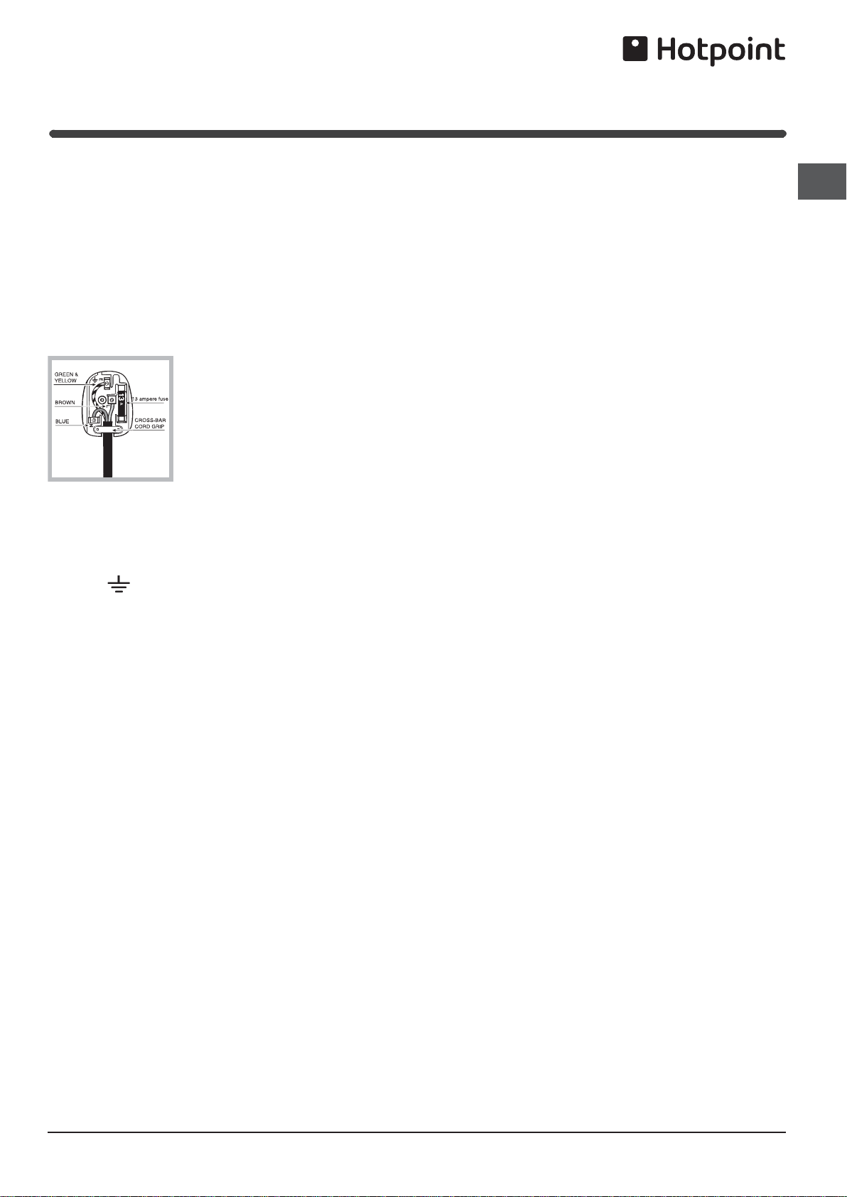
Fitting a new plug
GB
IMPORTANT
::
:
::
WIRES IN THE MAINS LEAD ARE COLOURED IN
ACCORDANCE WITH THE FOLLOWING CODE...
Green and Yellow - Earth
Blue - Neutral
Brown - Live
As the colours of the wires in the mains lead may not
correspond with the coloured markings identifying the
terminals in your plug, proceed as follows:
- Connect Green and Yellow wire to terminal marked
'E' or
or coloured Green and Yellow.
- Connect Brown wire to terminal marked 'L' or
coloured red or brown.
- Connect Blue wire to terminal marked 'N' or
coloured Black or Blue.
If a 13amp plug (BS 1363) is used it must be
fitted with a 13amp fuse. A 15amp plug must be
protected by a 15amp fuse, either in the plug or adaptor
or at the distribution board.
If you are in any doubt about the electrical
supply to your machine, consult a qualified
electrician before use.
CE Marking certifies that this appliance conforms to
the following EEC directives :
Low Voltage Equipment - 73/23/EEC & 93/68 EEC
Electromagnetic Compatibility 89/336/EEC, 92/31/EEC
& 93/68/EEC
PLEASE PHONE US TO REGISTER YOUR APPLIANCE AND ACTIVATE YOUR 5 YEAR PARTS GUARANTEE ON 08448 24 24 24
3
Reversing the Doors
plug I
food into insulated containers whist carrying out this operation.
1. Lay down the appliance on its back.You may require assistance to carefully lay the appliance on to
GB
*appliance lied down, must have protected the back side components (by using soft supports, EPS)
)gnigakcap lanigiro .e.i( lairetam evitcetorp elbatius a otno kcab sti
2. Working from the top of the appliance, remove the screws from the
door header cover .Remove the cover Fig.1
3. Unscrew the Hinge Pin securing the top of the Fridge door using
a suitable flat bladed screwdriver.Fig.2
4. Gently lift and slide the top door away from centre hinge pin and carefully
place to one side.Fig.3
5. Remove centre hinge block (2 screws) and spacer (if fitted).Fig.4
6. Slide bottom door upwards and away from lower hinge pin an
d place to
one side.Fig.5
7. Unscrew the bottom hinge pin from the white plastic block using
a suitable flat bladedscrewdriver.Fig.6
8. R
elease the bottom hinge block by removing two large hexagonheaded
bolts from underneath hinge plate, and the two plinthscrews (this then
releases the plinth and the white plastic hingeblock).
9. Slide out the blanking cover from plinth and refit on oppositeside.
10. Pass the white block through the space in plinth on the left side.
he plinth and block simultaneously.
Refit t
11. Refit 2 large bolts into white hinge block and the screws into theplinth.
They must be secure, but do not overtighten.
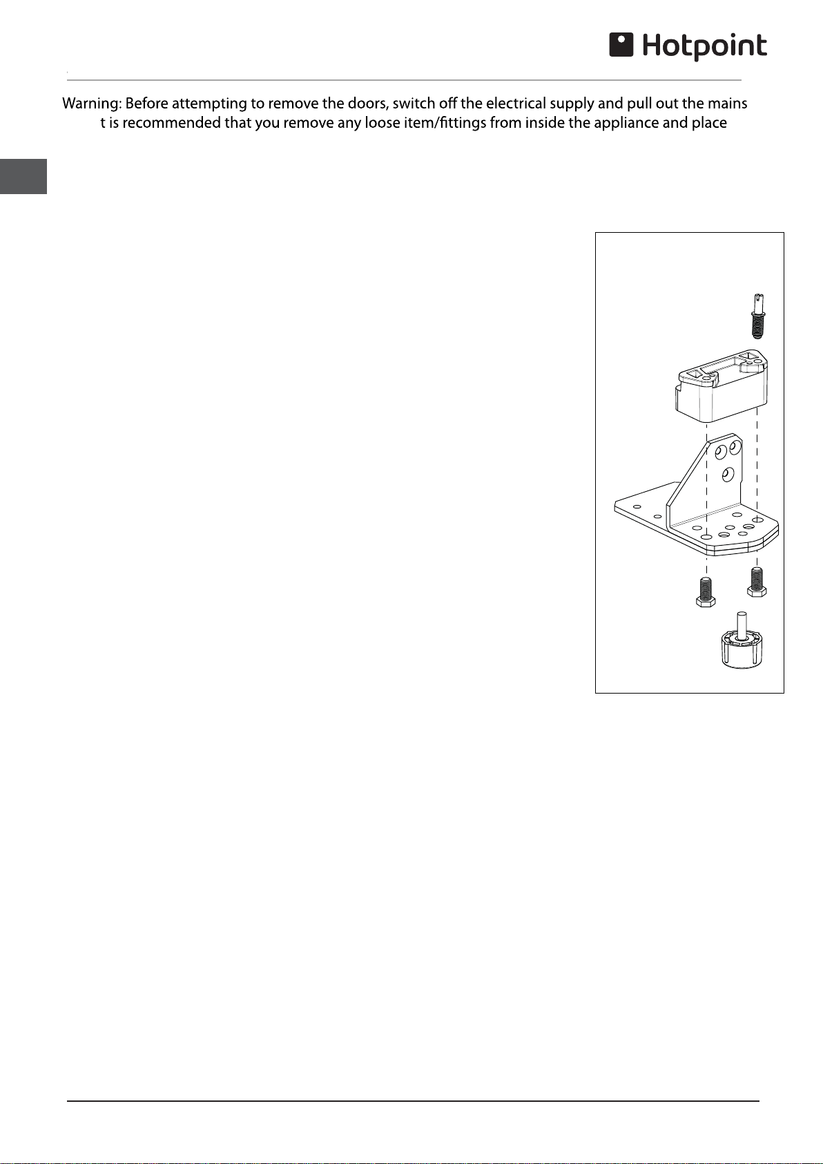
Hinge Block
Exploded View
Hinge
Pin
Hinge
Block
Hinge
plate
Hexagon
bolts
Foot
2. Place the bottom hinge pin in the outer hole on the hinge blockand
1
screw in securely with a suitable flat bladed screwdriver.
13. Remove and transfer all blanking caps and screws from thecentre left transom, over to the
holes on right vacated by thecentre hinge screws.
14.Refitting the Doors: Examine the tops and bottoms of both doors a
nd wherenecessary
transfer all hinge pin blanking plugs / plates to theopposite side - where fitted. They can be prised
out with smallflat bladed screwdriver.
15. Position
and slide the Freezer door onto the lower hinge pin.Ensure this is fully engaged.
16. Refit Centre Hinge (and spacer if fitted). Make sure the screwsare fully tightened. See Fig.4.
17. Remove the hinge blanking plate from top of the fridge. Remove right hand top hinge. Invert and
transfer over to left side using the original screws. Refit the blanking plate
to the opposite side.
18. Place the fridge door onto centre hinge pin and align with top hinge arm. Screw the top hinge pin
in securely.
19. Refit the door header cover to the fridge door with original screws
20. Finally check fri
dge and freezer door operation and stand the appliance upright.
21.Note:Replace loose items / fittings back into the appliance and leave it to stand for at least 2
hours before plugging in and switching on.
PLEASE PHONE US TO REGISTER YOUR APPLIANCE AND ACTIVATE YOUR 5 YEAR PARTS GUARANTEE ON 08448 24 24 24
4

Top Hinge Arm
GB
Door header cover
Fig.1
Fig.3
Top Hinge Pin
Fig.2
Step 5
Step 16
Fig.4
Step 6
Fig.5
PLEASE PHONE US TO REGISTER YOUR APPLIANCE AND ACTIVATE YOUR 5 YEAR PARTS GUARANTEE ON 08448 24 24 24
Fig.6
5
 Loading...