

Page 1
Indesit Company UK Ltd
© 2009 Reg. Office: Peterborough PE2 9JB Registered in London: 106725
Service
Information
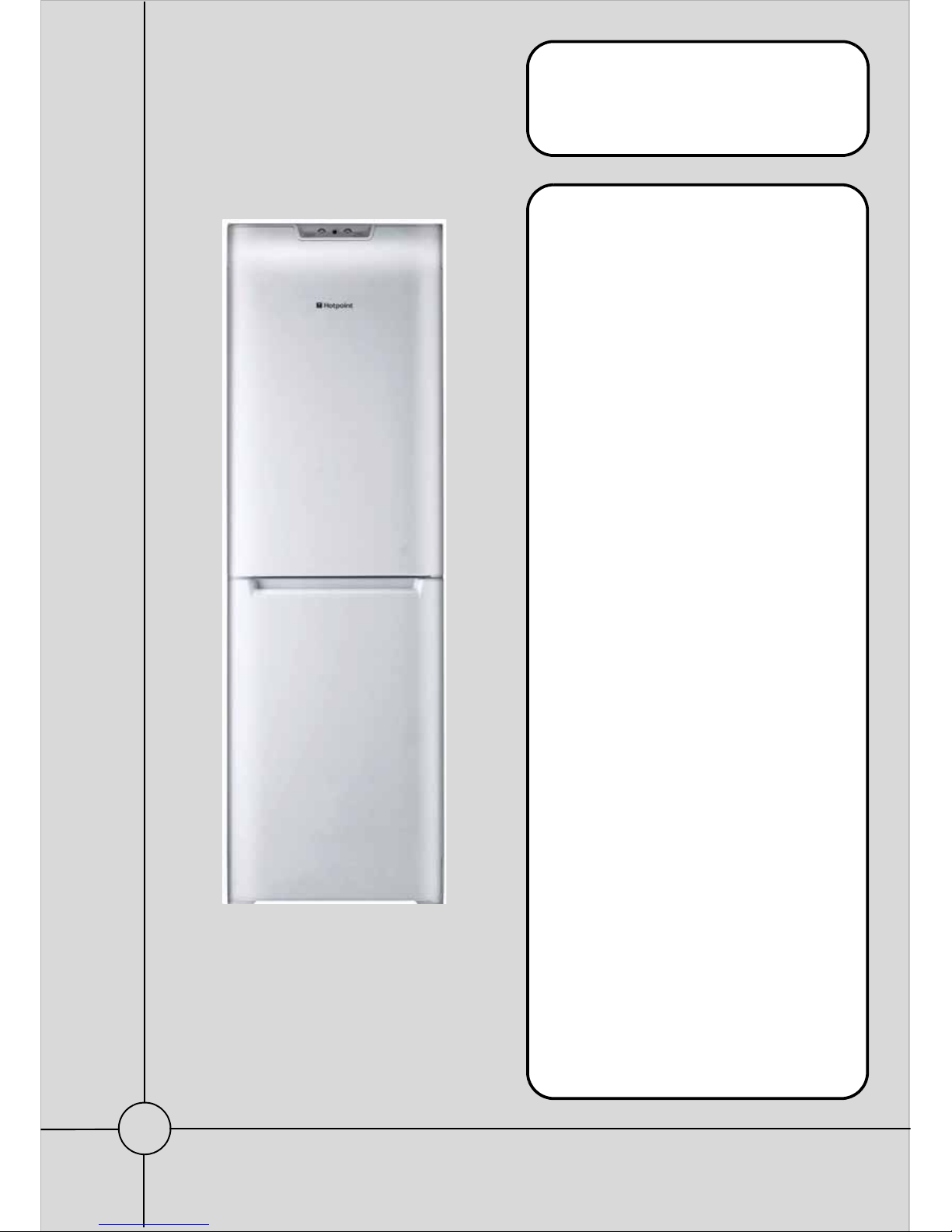
HOTPOINT
Freestanding
Frost Free
Fridge Freezers
(Version 2)
Refer to Insert below
Models Comm.
Covered Code
FF187EA 40729
FF187EG 39780
FF187EK 53950
FF187EP 39775
FF187EPL 53947
FF200EA 40733
FF200EG 40732
FF200EX 43503
FF200EK 53952
FF200EP 39777
FF200EPL 53949
IMPORTANT
THERE ARE TWO VERSIONS OF THE
ABOVE LISTED MODELS. TO IDENTIFY THE
CORRECT VERSION AND SERVICE
MANUAL SEE BELOW OR Page 5 FOR A
MORE DETAILED EXPLANATION:
VERSION 1 ~
THE POWER MODULE IS MOUNTED AT THE
REAR OF THE APPLIANCE ABOVE THE
COMPRESSOR COMPARTMENT.
VERSION 2 ~
THE POWER MODULE IS MOUNTED IN THE
CONTROL PANEL ONLY, THERE IS NO
REAR MOUNTED MODULE.
FOR VERSION 1 MODELS ~ REFER TO
SERVICE MANUAL 5407327
5407423 Issue 1 Feb. 2009
Page 2

2 of 36
Service Manual UK
Indesit Company
English
HEALTH AND SAFETY
For the servicing of refrigeration products, containing Isobutane R600a refrigerant.
These instructions are in addition to any other Company procedures already published.
Published primarily for Indesit Company engineers working in the UK or Southern Ireland, for
which these instructions are MANDATORY.
1. Only engineers who have been trained on the safe handling of Isobutane R600a refrigerant are
authorised to transport, store or carry out system repairs.
2. This manual is not intended as a comprehensive repair/maintenance guide to the appliance.
3. Must only be used by suitably qualified persons having technical competence, applicable product
knowledge, suitable tools and test equipment.
4. Servicing of electrical appliances must be undertaken with the appliance disconnected (unplugged
from the electrical supply).
5. Servicing must be preceded by earth continuity and insulation checks, plus refrigerant leak
detection.
6. Personal safety precautions must be taken to protect against accidents caused by sharp edges on
metal and plastic parts.
7. After servicing, the appliance must be rechecked for electrical safety.
8. Smoking, naked flames, or operating gas and/or electrical equipment (including cordless power
tools) are forbidden within the storage area, working area and vehicles used to transport Isobutane.
9. The carrying case for the scales and refrigerant must display a red flammability label
Part No. 8100063 that should be visible and readable at all times.
10. The vehicle and storage area must be ventilated as far as is reasonably practicable and the
aluminium case kept out of direct sunlight. The storage temperature of Isobutane should not exceed
50°C.
11. The vehicle transporting Isobutane (R600a) refrigerant must display a Red Flammable Gas warning
sticker (Part No. 8100063).
12. Engineers should not wear clothe s that are liabl e to cause static discharge ('electrostatic sparking').
13. Avoid working in small rooms.
14. Do not work in cellars.
15. Whenever possible move the applia nce into a larger open ar ea away from possible igni tion sources.
16. Request the customer to turn off all other electrical and gas appliances in the near vicinity of the
repair and note that it is done.
Customers should be advised to restrict activity within the near vicinity for a short time.
17. Isobutane refrigerant must be vented to atmosphere, (outside of the premises e.g. via open window
through the clear plastic hose supplied).
18. Isobutane is heavier than air and must not be vented within 3 metres of the following: sewer cover,
cellar, drain or any similar construction lower than ground level, boiler air inlet/outlet, or near any
possible source of ignition.
continued...
Page 3

3 of 36
Indesit Company
Service Manual UK English
HEALTH AND SAFETY
19. Working with a naked flame i.e. soldering or brazing is forbidden. Unless otherwise stated,
pipework connections must only be made using the Lokring coupling system.
20. Electronic leak detectors with high voltage tips must NOT be used with any Isobutane (R600a).
21. All equipment used for this activity must be checked re gularly and maintained in a safe working
condition; parts must be replaced as required.
Information Regarding Isobutane Canisters
1. The maximum quantity of Isobutane an engineer should hold or store at any one time is two 1kg
net aluminium canisters, supplied individu ally as Part No. 2602600.
2. Canisters must be stored inside the aluminium case with the weighing scales for protection from
possible damage and heat. The aluminium case must NEVER be placed next to a heat source or
in direct sunlight.
3. Isobutane must only be dispensed to the applia nce fr om the 1kg n et alumini um canister p laced in
an upright position on the weighing scales provided.
4. All used canisters must be a returned as scrap and therefore, left out for the driver to collect and
return for disposal.
5. Canisters must not be punctured or the internal valve damaged.
6. Before storing the canister it must have the extr action tap valv e removed an d the internal va lve of
the canister checked for leakage using leak detector (Leak Detector: Part No. 5700043).
7. All used canisters and those found to be leaking should be exhausted to atmosphere to ensure
they are emptied completely. Refer to the following paragraph.
8. Refit the extraction tap if necessary, open the tap and then invert the canister.
This must be done outside in open air away from buildings and ignition sources and complying with
Item 18 on previous page.
Page 4
4 of 36
Service Manual UK
Indesit Company
English
CONTENTS
Health and Safety . . . . . . . . . . . . . . . . . . . . . . . . . . . . . . . . . . . . . . . . . . . . . . . . . . . . . . . . . 2 - 3
Index & Serial Number / Product Identity . . . . . . . . . . . . . . . . . . . . . . . . . . . . . . . . . . . . . . . . .4
Introduction . . . . . . . . . . . . . . . . . . . . . . . . . . . . . . . . . . . . . . . . . . . . . . . . . . . . . . . . . . . . . . 5 - 6
Specifications . . . . . . . . . . . . . . . . . . . . . . . . . . . . . . . . . . . . . . . . . . . . . . . . . . . . . . . . . . . . 7 - 8
Product Description with Image. . . . . . . . . . . . . . . . . . . . . . . . . . . . . . . . . . . . . . . . . . . . . 9 - 10
Component Fuction. . . . . . . . . . . . . . . . . . . . . . . . . . . . . . . . . . . . . . . . . . . . . . . . . . . . . . 11 - 12
Alarm Conditions. . . . . . . . . . . . . . . . . . . . . . . . . . . . . . . . . . . . . . . . . . . . . . . . . . . . . . . . . . . .12
Auto-Test & Fault Conditions. . . . . . . . . . . . . . . . . . . . . . . . . . . . . . . . . . . . . . . . . . . . . . 13 - 14
Explanation of Auto-Test Codes . . . . . . . . . . . . . . . . . . . . . . . . . . . . . . . . . . . . . . . . . . . 15 - 17
Airflow . . . . . . . . . . . . . . . . . . . . . . . . . . . . . . . . . . . . . . . . . . . . . . . . . . . . . . . . . . . . . . . . 18 - 19
Power / Control Module Parameters . . . . . . . . . . . . . . . . . . . . . . . . . . . . . . . . . . . . . . . . 20 - 21
Fault Diagnosis Quick guide . . . . . . . . . . . . . . . . . . . . . . . . . . . . . . . . . . . . . . . . . . . . . . 22 - 23
Servicing & Dismantling Instructions . . . . . . . . . . . . . . . . . . . . . . . . . . . . . . . . . . . . . . . 24 - 25
Programming the Module. . . . . . . . . . . . . . . . . . . . . . . . . . . . . . . . . . . . . . . . . . . . . . . . . 26 - 30
Wiring Connection Information . . . . . . . . . . . . . . . . . . . . . . . . . . . . . . . . . . . . . . . . . . . . 31 - 32
Theoretical Wiring Diagram . . . . . . . . . . . . . . . . . . . . . . . . . . . . . . . . . . . . . . . . . . . . . . . . . . .33
Thermistor Sensor Information . . . . . . . . . . . . . . . . . . . . . . . . . . . . . . . . . . . . . . . . . . . . . . . .34
Door Reversal Instructions. . . . . . . . . . . . . . . . . . . . . . . . . . . . . . . . . . . . . . . . . . . . . . . . . . . .35
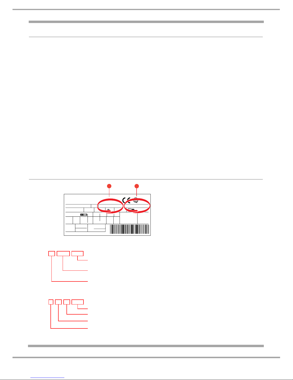
PRODUCT IDENTITY
Mod. - - - - - -
TI
Cod.
93139180000 S/N 704211801
220 - 240 V- 50 Hz 150 W
W
Fuse
A
Max 15 w
Total
Gross
Bruto
Brut
Compr.
Kompr.
Syst.
R134 a
kg 0,090
Gross
Bruto
Brut
340
Net
Util
Utile
Gross
Bruto
Brut
Freez. Capac
Poder de Cong
75
Made in - - - - 13918
Test
P.S-I.
Pressure
HIGH-235
LOW 140
kg/24 h
4,0
Class
Clase
N
Classe
1
2
Example
1 Industrial Code:
93 13918 0000
0000 original production
Commercial Code*
Factory of origin
2 Serial Number:
704 1801
Build number that day, e.g. 1801th built
Day of manufacture, e.g. 21
st
of month
Month of manufacture, e.g. April
21
Year of manufacture, e.g. 2007
*Vital for correct model information and system identification
Other numbers denote major production changes
Page 5
5 of 36
Indesit Company
Service Manual UK English
MODEL VERSION IDENTIFICATION
The models included in this publication are 1870 & 2000 mm high no-frost fridge freezers that were
introduced in Jan 2008.
There are two versions of the above range of models that share the same model number and commercial
code. The versions can be identified by the serial number on the rating plate behind the bottom drawer on
the rear wall and/or by the power module position.
NOTE ~ If the first three digits of the serial number commence between 710or 801 you must confirm the
location of the power module to positively identify the model version.
See version descriptions and photos below:
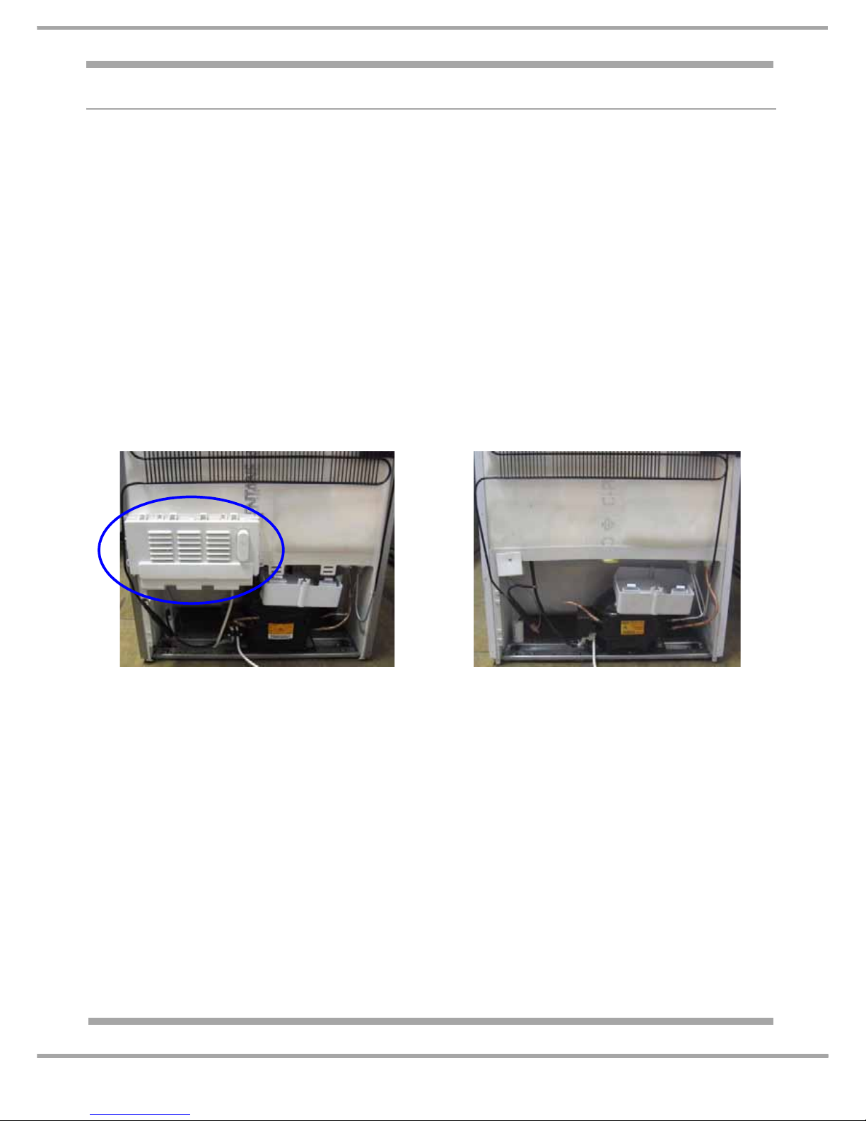
VERSION 1: Refer to Service Manual 5407327 (C00221355) See photo below.
Models produced on or before serial number 801019999.
The power module is mounted at the rear of the appliance above the compressor compartment.
VERSION 2: Refer to this Service Manual
Models commencing with serial number 801020001 See photo below.
The power module is mounted in the top facia (control panel) of the appliance.
For banding and colour information, refer to the Front Cover and/or Specifications page.
VERSION 1:
The power module is mounted at the rear of the
appliance above the compressor compartment
VERSION 2:
The power module has been re-located and is
mounted in the top front facia (control panel).
Page 6

6 of 36
Service Manual UK
Indesit Company
English
MODEL INTRODUCTION
All models are similar with regard to the furniture design, but there are variations for energy consumption
and exterior colour.
Model FF187E interior:
The interior of the fridge has glass shelves, chromed steel wine rack and two salad bins with a glass cover.
The door has a bottle shelf with retainer, dairy shelf with a lid and one commodity shelf.
The freezer section has four drawers of varying sizes, the lower two drawers have ice cube compartments
inserted in the top of the drawer fronts.
Model FF200E interior:
The interior of the fridge has glass shelves, chromed steel wine rack, fresh box (chiller compartment) and
one full width salad bin with a glass cover. The door has a deep bottle shelf with retainer, dairy shelf with a
lid and one commodity shelf. The freezer section has four drawers of varying sizes, the lower two drawers
have ice cube compartments inserted in the top of the drawer fronts.
The electronic thermostat and LED interface are all part of the power module mounted in the top facia of the
appliance; The fridge and freezer temperature settings are adjusted by operating the control knob s mounted
in the top facia. All functions are monitored and actioned by the power module mounted in the top facia of
the appliance. The fridge baffle is of a motorised type, mounted in the multi-flow unit. The fridge temperatu re
is monitored by a sensor mounted in the return ducting behind the fridge multiflow unit.
The fridge and freezer temperatures are monitored by sensors located in the following locations:
1. Fridge Sensor ~ mounted in the return duct behind the fridge multiflow unit;
2. Freezer Air Sensor ~ mounted in the lower right side of the freezer cabinet liner;
3. Freezer Evaporator Sensor ~ inserted into the top right of the evaporator.
The sensors (thermistors) are not replaceable because they are for the most part foamed behind the liner
where they are not affected by moisture. The sensors are double insulated and in the unlikely event of
failure a section of the power module is programmed to respond and control the functions on a timed basis
from there on in.
The appliance is "no-frost" design (Full Frost-Free) so defrosting is automatic.
All models have rear wheels located in the compressor base plate with adjustable feet fitted at the front.
Doors are reversible, but do require a T20 Torx key to remove the plinth / kick strip.
The climate class is SN / ST signifying that it is designed to operate in ambient temperatures between
+10°C to +38°C. As with many refrigeration appliances, it is important that it is installed and operated within
the recommended ambient temperature range and that there is adequate ventilation.
ANTI-BACTERIA (Hygiene Control)
Some models have anti-bacteria protection (hygiene control) - built in protection for life of the product. Food
safety is becoming increasingly important to consumers with more and more cases of food poisoning.
The hygiene control is built into the plastic of the fridge interior during manufacture so it cannot wash or
wear out. It provides permanent protection against bacteria as it reduces on contact the spread of food
poisoning bacteria, which can cause contamination and odour.
It gives extra hygiene reassurance as it kills or inhibits the growth of any bacteria, which may come into
contact with the interior surfaces of the fridge.
The anti-bacteria protection is approved safe for use in food contact applications by the European Scientific
Committee for Food and has proven safe over many in personal care and household cleaning
products.products.
Page 7
7 of 36
Indesit Company
Service Manual UK English
SPECIFICATIONS
GENERAL:
Manufactured in: UK (76)
Appliance Type: Freestanding Fridge Freezer
Static / No-Frost: No-Frost
Doors Hinging - Right Hand
Reversible: Yes
Plug/Cable: UK/ 1.6M
FF187E FF200E
Energy Class A” “A”
Power Consumption kWh/24hr: 0.95 0.99
Annual Consumption kWh/yr : 347.0 361.0
Noise level: 43dB 43dB
Climate Class: SN.N.ST = 10ºC to 38ºC SN.N.ST = 10ºC to 38ºC
(Rating plate)
Refrigeration Type: No-Frost / Fin On Tube (FOT) Evaporator
DIMENSIONS & WEIGHT:
Models: FF187E FF200E
Height: 1870 mm 2000 mm
Width: 600 mm 600 mm
Depth: 655 mm 655 mm
Weight Gross: 67.4 kg 78.0 kg
Weight Net: 64.5 kg 67.4 kg
CAPACITIES / VOLUME:
Models: FF187E FF200E
Fridge Freezer Fridge Freezer
Gross 175 litre 113 litre 205 litre 113 litre
Net 173 litre 84 litre 202 litre 84 litre
Freezing Capacities 24 hrs 8 kg 8 kg
Conservation Time 12 hours 12 hours
Star Rating 4 Star **** 4 Star ****
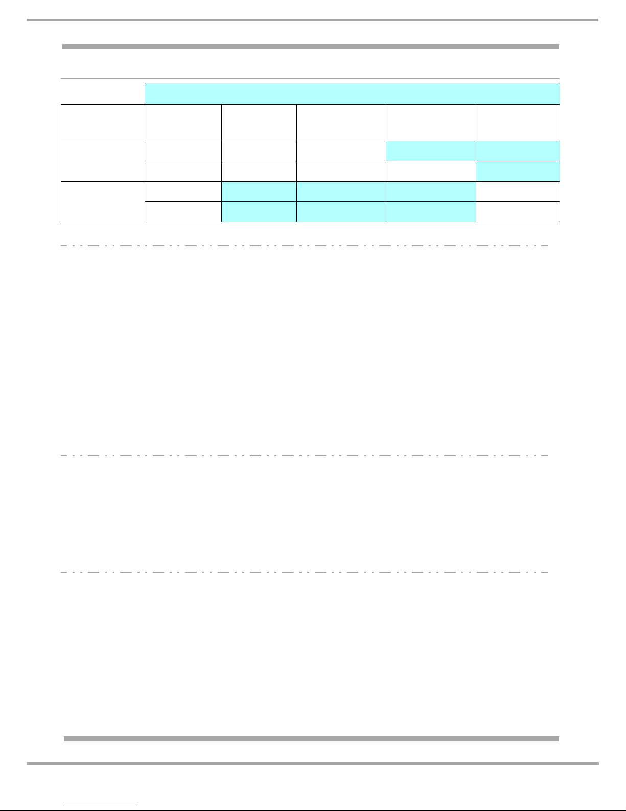
Colour
Introduction
Date
Polar - P Graphite - G Aluminium - A Stainless Steel
(inox) - X
Black - K
Jan 2008
FF187EP FF187EG FF187EA
FF200EP FF200EG FF200EA FF200EX
May 2008
FF187EPL
FF187EK
FF200EPL
FF200EK
Page 8

8 of 36
Service Manual UK
Indesit Company
English
TECHNICAL DATA:
Power Supply Voltage: 220/240 V
Power Supply Frequency: 50 Hz
Absorbed Power: 180 W
Absorbed Current: 0.5 A
COMPRESSOR WINDINGS Ω
FF187E FF200E
Manufacturer: Jiaxipera Tecumseh
Type I/D: ZBT1114CY TWB1370MJS
Winding Resistances:
Start: 16.0 Ω 26.75 Ω
R un: 13.3 Ω 15.75 Ω
Refrigerant Type / Grams: R600a - Refer to the appliance rating plate
Capacitor: Refer to Parts List
HEATER RESISTANCES
Evaporator Defrost Heater: 387.2 Ω
Gutter Heater: 1.61 KΩ
Thermal Fuse: 72 ºC
Page 9
9 of 36
Indesit Company
Service Manual UK English
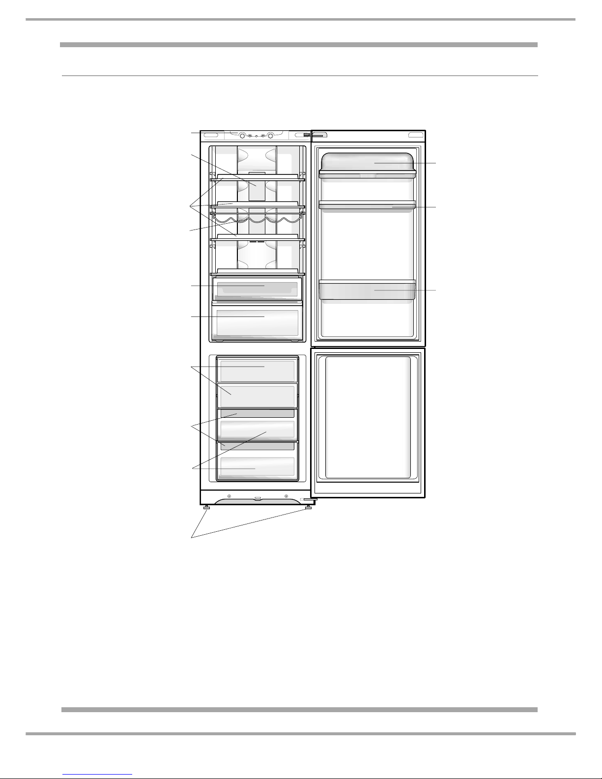
DESCRIPTION OF APPLIANCE
Detailed View
** Varies by number and/or position.
* Available only on certain models.
Removable lidded
shelf with EGG TRAY
Removable multipurpose
SHELF**
BOTTLE shelf
Control panel
FRESH BOX
Compartment
FF200E models only
FREEZER and
STORAGE compartment
STORAGE compartment
Levelling FEET
ICE CARE ice tray**
FRUIT and VEGETABE bin**
FF187E models have two half bins
LAMP
WINE RACK*
SHELVES**
Page 10
10 of 36
Service Manual UK
Indesit Company
English
DESCRIPTION OF APPLIANCE:
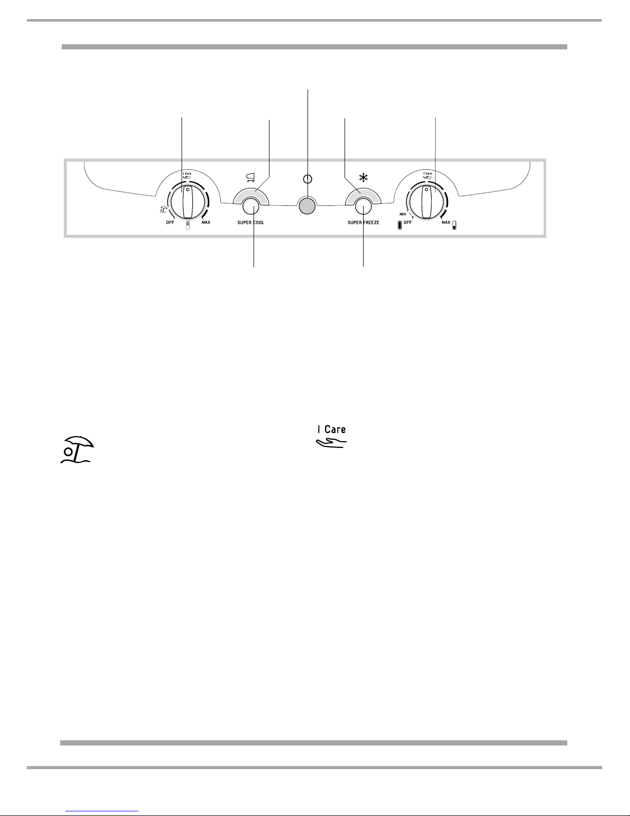
NOTE: - The indicator lights are also used to indicate an unusual temperature increase in the
freezer compartment.
See Alarm Conditions on Page 12.
The SUPER COOL (quic k cool) function l owers
the temperature of the refrigerator compartment
rapidly. When the button is pressed it
illuminates the SUPER COOL indicator light.
The REFRIGERATOR OPERATION knob
allows you to adjust the refrigerator
compartment from MIN (warmer) to MAX
(colder).
The HOLIDAY function will minimise
energy usage when away on holiday.
It is not necessary to switch the
appliance off. It allows the appliance to maintain
the temperature of the refrigerator compartment
at approximately 15°C (which can be used to
conserve make-up and beauty products).
The FREEZER OPERATION knob MUST be
set to MIN in order to preserve the frozen food.
An acoustic signal sounds when this function is
enabled or disabled.
The SUPER FREEZE (fast freeze) function
allows the freezing of fresh food. When the
button is pressed it illuminates the SUPER
FREEZE indicator light.
The FREEZER OPERATION knob allows you
to adjust the freezer compartment from MIN
(warmer) to MAX (colder).
Selecting this position allows the
relevant compartment to achieve the
optimal temperature setting for energy
saving levels.
FREEZER OPERATION knob
OFF ~ Selecting this position switches the
appliance OFF including the refrigerator
compartment.
REFRIGERATOR OPERATION knob
OFF ~ Selecting this position switches the
refrigerator compartment OFF only.
SUPER FREEZE
Button
REFRIGERATOR
OPERATION
Knob
SUPER COOL
Button
SUPER COOL
Indicator light
SUPER FREEZE
Indicator light
POWER
Indicator light
FREEZER
OPERATION
Knob
Page 11

11 of 36
Indesit Company
Service Manual UK English
COMPONENT FUNCTION
General Information
The power module is made up of a number of smaller individual modules (sections), each one
controlling a functional component. The modules are linked together when required to control a
particular function or function s. The linking of the indivi dual modules is optional and therefore allows for
each module to be switched ON or OFF, this is determined from the data stored or collected by the
modules and the results of module comparisons.
The power module memory stores information such as temperatures and times.
Having individual set of parameter values built in to it, directly aimed at providing the specific control
needs for the physical and system characteristics of the model type.
Fridge & Freezer Control
The power module monitors the fridge and freezer air senso rs, comparing their sensor resistance values
with the cut-in and cut-out parameter values stored in its memory.
Although the parameters are set, they allow for adjustment within those parameters so that the user has
control. The results from the comparisons will determine if cooling is initiated, other circuits of the
module will also use the results.
The power module will enable normal operation provided there is no malfunction condition.
Fridge or Freezer Malfunction Module
The fridge or freezer malfunction module enables the appliance to continue operating in the unlikely
hood of the fridge or freezer sensors failing. Pre-set timed functions stored in the module memory are
used to cycle cold request on and off.
A malfunction occurs when the fridge or freezer cabinet sensors return a value to the module of either
Open or Closed circuit, rather than a particular resistance value.
Freezer Evaporator Fan Module
The freezer fan is located above the evaporator c oil and is d esigned to di stribute the cold air pro duced
by the evaporator coil uniformly inside the freezer compartment and when necessary in the fridge
compartment.
The freezer fan is managed by the module and is switched on/off after a preset time interval that is
parameterised in the module memory after a compressor start/stop.
The defrost procedure is preceded by activation of the fan for a timed interval that is parameterised in
the module memory. The fan will not operate when in the defrost cycle.
After the defrost cycle the fan starts after a timed interval following a compressor start, this interval is
also parameterised in the module memory; this interval is different from the interval programmed for
normal operating conditions.
Electronic Motorised Damper Assembly (Baffle)
The purpose of the damper is to a llow the c old air pr oduced by the free zer evapo rator to be distributed
inside the refrigerator compartment.
The damper is located behind the fridge multi-flow unit in the upper section. It is controlled by a
thermistor positioned into the exhaust (return) duct connecting the evaporator to the damper.
Cold air from the evaporator is distributed in the refrigerator compartment by open ings on the multi-flow
unit. (See the Air Flow Diagram on page 18.)
Page 12
12 of 36
Service Manual UK
Indesit Company
English
Compressor
The compressor is managed by the power module and switches on whenever a demand for cooling is
received.
There are situations of cooling demand in which the compressor remains off. These are as follows:
1. Compressor protection: the compressor switches on once a minimum safety time lag has elapsed
since the last power-off, thereby allowing the refrigerant gas pressure to reach a point of equilibrium
in the refrigerant circuit. The same minimum safety time is observed in the event of a mains power
interruption (voluntary or involuntary). This compressor protection strategy is observed only after
the product has been operating continuously for the numbe r of hours defined in the module
memory.
2. Long periods of activity: if the compressor remains on for more than a value set in module
memory it is switched off, even in the presence of a cooling demand.
3. Pause after defrost: at the end of the defrost cycle the compressor observes a protection time
parameterised in the module memory so that the water formed during the defrost can be completely
drained.
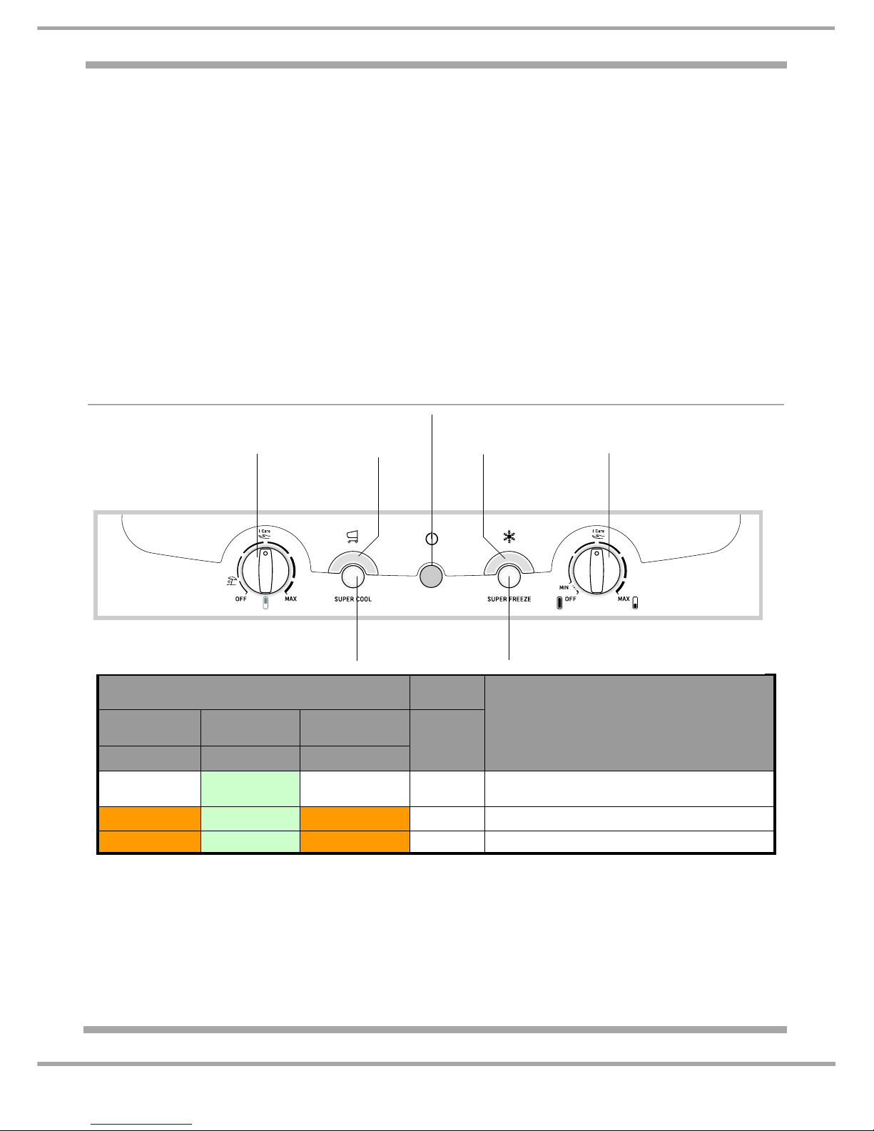
ALARM CONDITIONS
* Fridge Interior Lamp also Flashes.
** Plus Bleeping - Open/Close the fridge door to cancel audible bleeping.
*** In these situations the freezer will try to maintain 0°C so food will not refreeze. (Refer the User to
the Troubleshooting page in their user book ~ it explains what action to take with the defrosted
food.)
To restore the 'FREEZER WARM' Alarm condition back to normal operation, turn the freezer knob OFF
then ON again.
LEDs
ALARM
CONDITION
Super Cool Mains
Super
Freeze
Audible
Bleep
Amber Green Amber
ON or OFF
ON ON or OFF YES**
Fridge door open for more than 2
minutes*
FLASHING ON FLASHING YES** Freezer too warm***
FLASHING FLASHING FLASHING YES** Freezer very warm***
SUPER FREEZE
Button
REFRIGERATOR
OPERATION
Knob
SUPER COOL
Button
SUPER COOL
Indicator light
SUPER FREEZE
Indicator light
POWER
Indicator light
FREEZER
OPERATION
Knob
Page 13

13 of 36
Indesit Company
Service Manual UK English
AUTO-TEST
This helps with a quick check of the loads and sensors (thermistors), which otherwise are difficult to
activate. NOTE: - Before using the AUTO-TEST it is advisable to check the correct operation of the
Mains (Green), Super Cool and Super Freeze (Amber) LEDs and the fridge interior lamps, which are
used for signalling possible malfunctions. Ensure both the Super Cool and Super Freeze have not been
selected before starting the Auto-Test.
TO ACTIVATE TO DEACTIVATE CHECK RESPONSE
NO-FROST
MODELS
FF187E
&
FF200E
1. Open the fridge
door and keep
ajar while in
auto-test.
2. Turn the fridge
and freezer
control knobs to
the minimum
setting
(appliance OFF
position).
3. Push and hold
the Super
Freeze button in
until all three
LED lights
illuminate at the
same time.
(The LED lights
will extinguish
after 5
seconds.)
Automatically:
After 300 seconds
from start of the
Auto-Test it will be
deactivated.
Manually by:
Turning the fridge
and freezer control
knob from the OFF
position.
Or
Switching OFF the
power supply
First Stage:
Fridge baffle opens &
evaporator fan runs Check for baffle
operation, feel for
airflow at both fridge
and freezer vents.
Second Stage:
Heaters and Sensors
check -
Feel for warmer air
from freezer vents
during defrost heater
check.
Third Stage:
Fridge baffle closes Check for baffle motor
operation.
Finish of Auto Test:
Evaporator fan stops
and one beep sounds.
No Fault:
Super Cool &
Super Freeze
LEDs OFF
and
Power LED ON
Fault Detected:
Fridge interior
lamp flashes if
during the
checks
described a fault
is detected.
The console
LED lights will
determine the
actual fault
code.
Refer to the
Table on
page14.
Page 14
14 of 36
Service Manual UK
Indesit Company
English
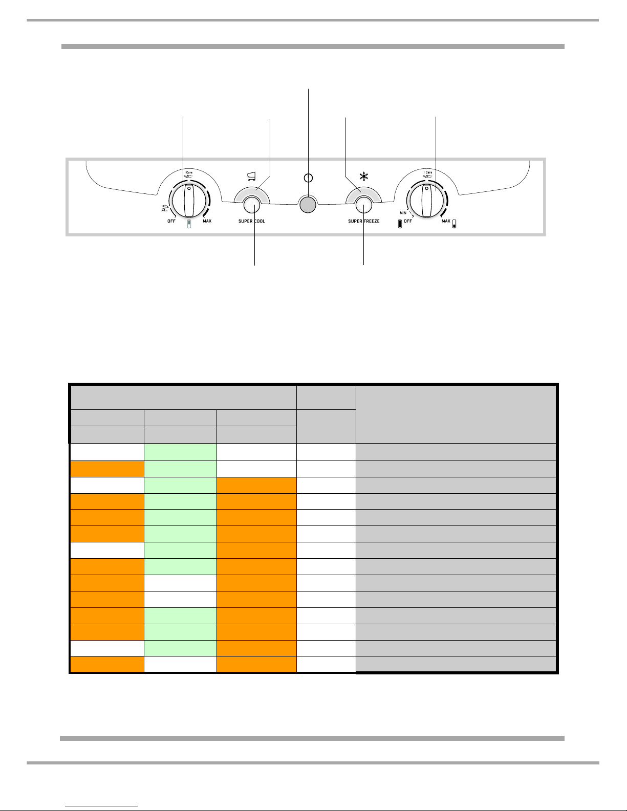
FAULT CONDITIONS
Alarm Conditions: are signalled to the user by flashing LEDs and accompanied by an audible beep.
Fault Conditions: are signalled to the engi neer duri ng an Auto -Test by flashing LEDs with NO audible
beep.
See chart below for Auto-Test fault codes and pages 15 and 17 for Fault Code explanations.
LEDs
AUTO TEST FAULT CODES
(See pages 15 to 17 for explanations)
Super Cool Mains Super Freeze
Audible
Bleep
Amber Green Amber
OFF FLASHING
OFF NO F 01
ON FLASHING
OFF NO F 02
OFF FLASHING
ON NO F 03
ON FLASHING
ON NO F 04
FLASHING FLASHING
ON NO F 05
ON FLASHING
FLASHING NO F 06
OFF FLASHING
FLASHING NO F 07
FLASHING FLASHING
FLASHING NO F 09
ON OFF
ON NO F 14
FLASHING OFF
FLASHING NO F 20
ON ON
FLASHING NO F 21
FLASHING ON
ON NO F 22
OFF ON
FLASHING NO
F 24
ON OFF
FLASHING NO
F 25
SUPER FREEZE
Button
REFRIGERATOR
OPERATION
Knob
SUPER COOL
Button
SUPER COOL
Indicator light
SUPER FREEZE
Indicator light
POWER
Indicator light
FREEZER
OPERATION
Knob
Page 15
15 of 36
Indesit Company
Service Manual UK English
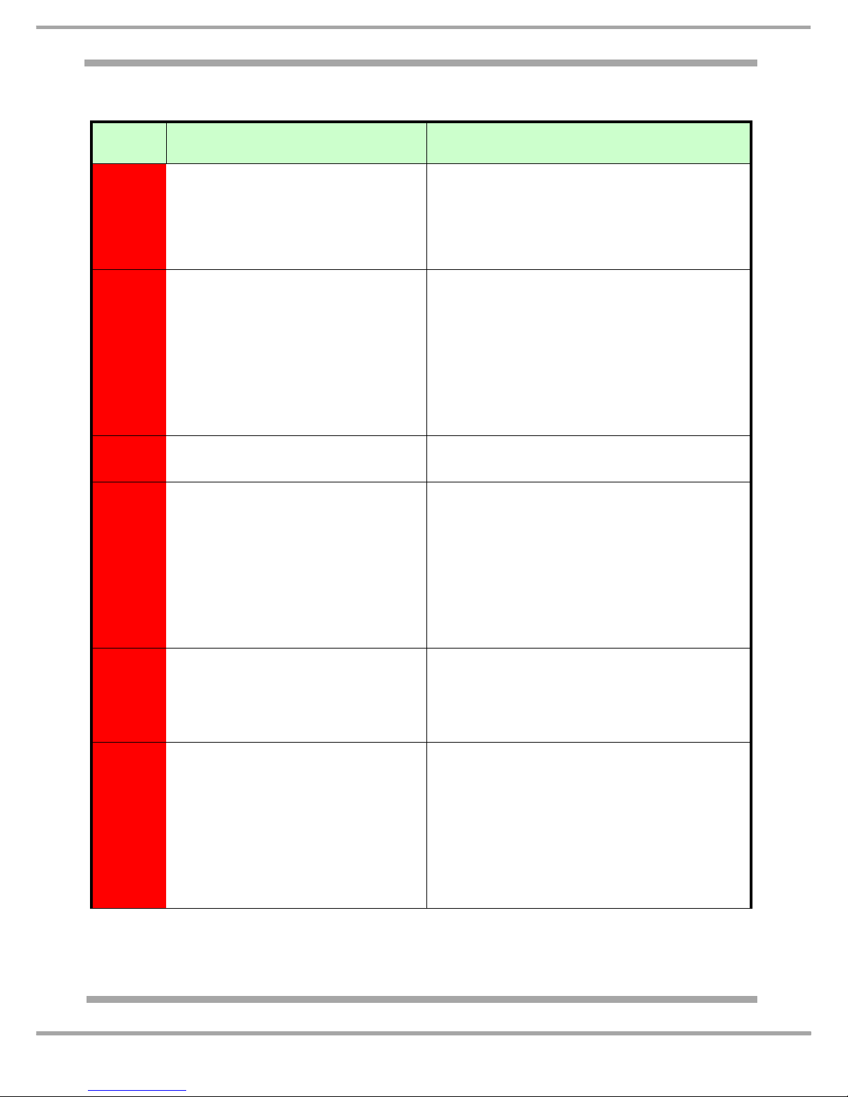
EXPLANATION OF AUTO-TEST CODES
(The fault codes below are generic and also associate with other models not listed in this manual)
FAULT
CODE
CAUSE CORRECTIVE ACTION
F 01
Compressor Relay Sticking
• Check for moisture on module, check
connections especially on connector E1;
• Check compressor connections;
• Refer to Diagnostic Manual 5407355;
• Replace power module;
• Replace compressor.
F 02
Compressor Relay Open
• Check module connections especially on
connector E1;
• Check resistance reading between pins 9
and 7 of connector E1;
• Check that the compressor has not
stopped due to over-temperature
conditions (thermal cut-out open);
• Replace power module;
• Replace compressor.
F 03
Faulty Power Module • Replace power module.
F 04
Evaporator Fan Motor Not Running
• Check module connector E1;
• Check resistance reading between pins 1
and 8 of connector E1;
• Check the connection of the evap orator fan
motor to the freezer compartment wiring
junction box;
• Replace evaporator fan assembly;
• Replace power module.
F 05
Electronic/Motorised Baffle Does Not
Open/Close
• Check module connector E2;
• Check baffle connection to the connector
block foamed in behind the multi-flow unit;
• Replace baffle;
• Replace power module.
F 06
Defrost Heater Triac Short-Circuit
• Check module connector E1;
• Check resistance reading between pins 2
and 6 of connector E1;
• Check defrost heater connections and
freezer compartment wiring junction box;
• Replace defrost heaters;
• Replace power module.
Page 16
16 of 36
Indesit Company
Service Manual UK English
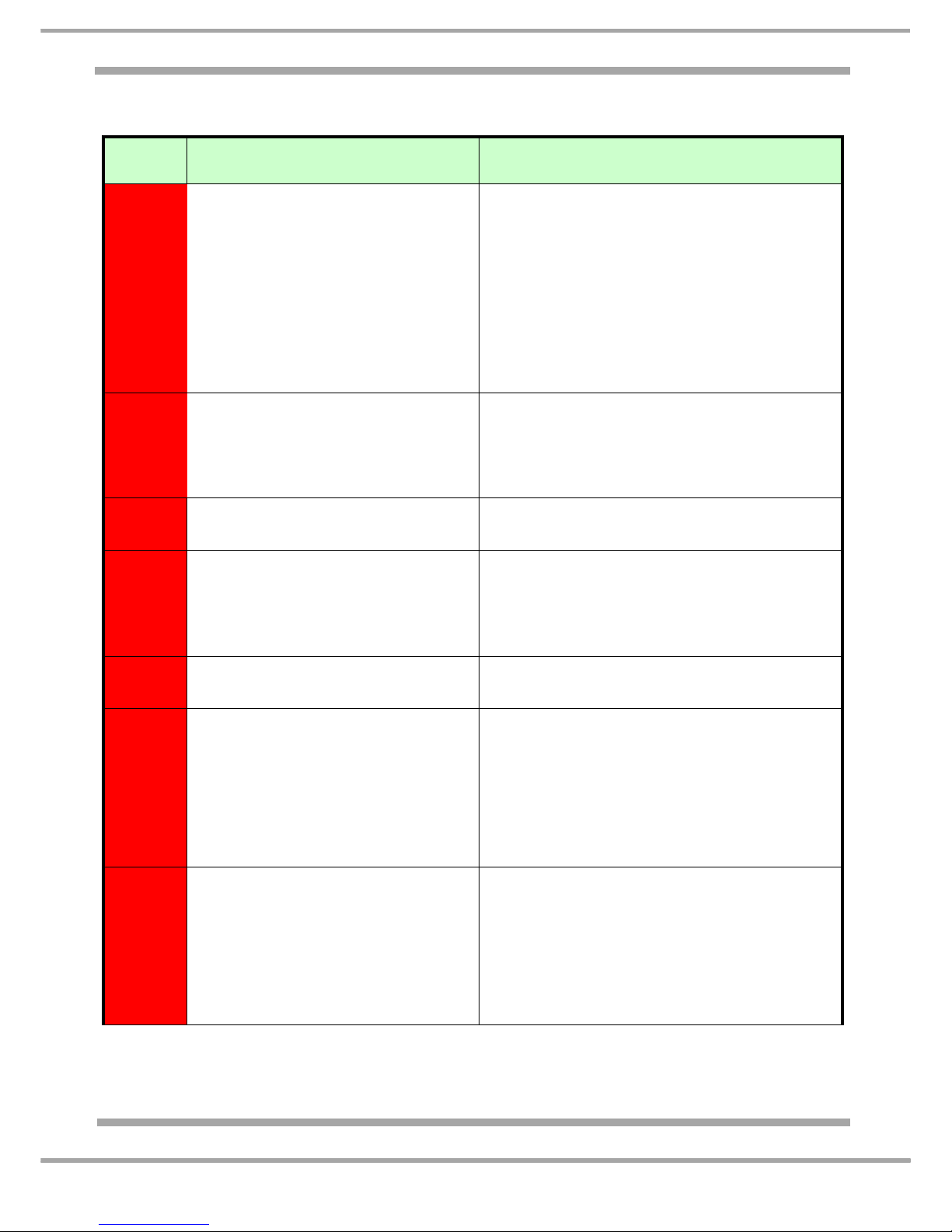
EXPLANATION OF AUTO-TEST CODES
(The fault codes below are generic and also associate with other models not listed in this manual)
FAULT
CODE
CAUSE CORRECTIVE ACTION
F 07
Defrost Heaters
• Check module connector E1;
• Check resistance reading between pins 2
and 6 of connector E1;
• Check defrost heater and gutter heater
connections and freezer compartment
wiring junction box;
• Check that the thermal fuses are not open
circuit;
• Replace defrost heaters;
• Replace power module.
F 09
Module not programmed
• Re-programme module with correct
settings file;
• Replace power module.
F 14
Faulty power module • Replace power module.
F 20
All fridge lamps fail to illuminate
• Check module connector E1;
• Check resistance reading between pins 3
and 4 of connector E1;
• Replace lamps;
• Replace power module.
F 21
NTC ambient sensor on power
module faulty.
• Replace power module.
F 22
Fridge air NTC sensor
open / short circuit
• Check module connector E4;
• Check NTC sensor, ensuring that the
values read between pins 3 and 4 of
connector E4 is compatible with the values
in the “Sensor Resistance Table” on
page 34, (also heat the sensor by holding i t
with your hand / fingers where pos sible and
check the change in the resistance value);
F 24
Freezer air NTC sensor
open / short circuit
• Check module connector E4;
• Check NTC sensor, ensuring that the
values read between pins 5 and 6 of
connector E4 is compatible with the values
in the “Sensor Resistance Table” on
page 34, (also heat the sensor by holding i t
with your hand / fingers where pos sible and
check the change in the resistance value);
Page 17
17 of 36
Indesit Company
Service Manual UK English
F 25
Freezer evaporator NTC sensor
open / short circuit
• Check module connector E4;
• Check NTC sensor, ensuring that the
values read between pins 1 and 2 of
connector E4 is compatible with the values
in the “Sensor Resistance Table” on
page 34, (also heat the sensor by holding i t
with your hand / fingers where pos sible and
check the change in the resistance value);
Page 18
18 of 36
Indesit Company
Service Manual UK English
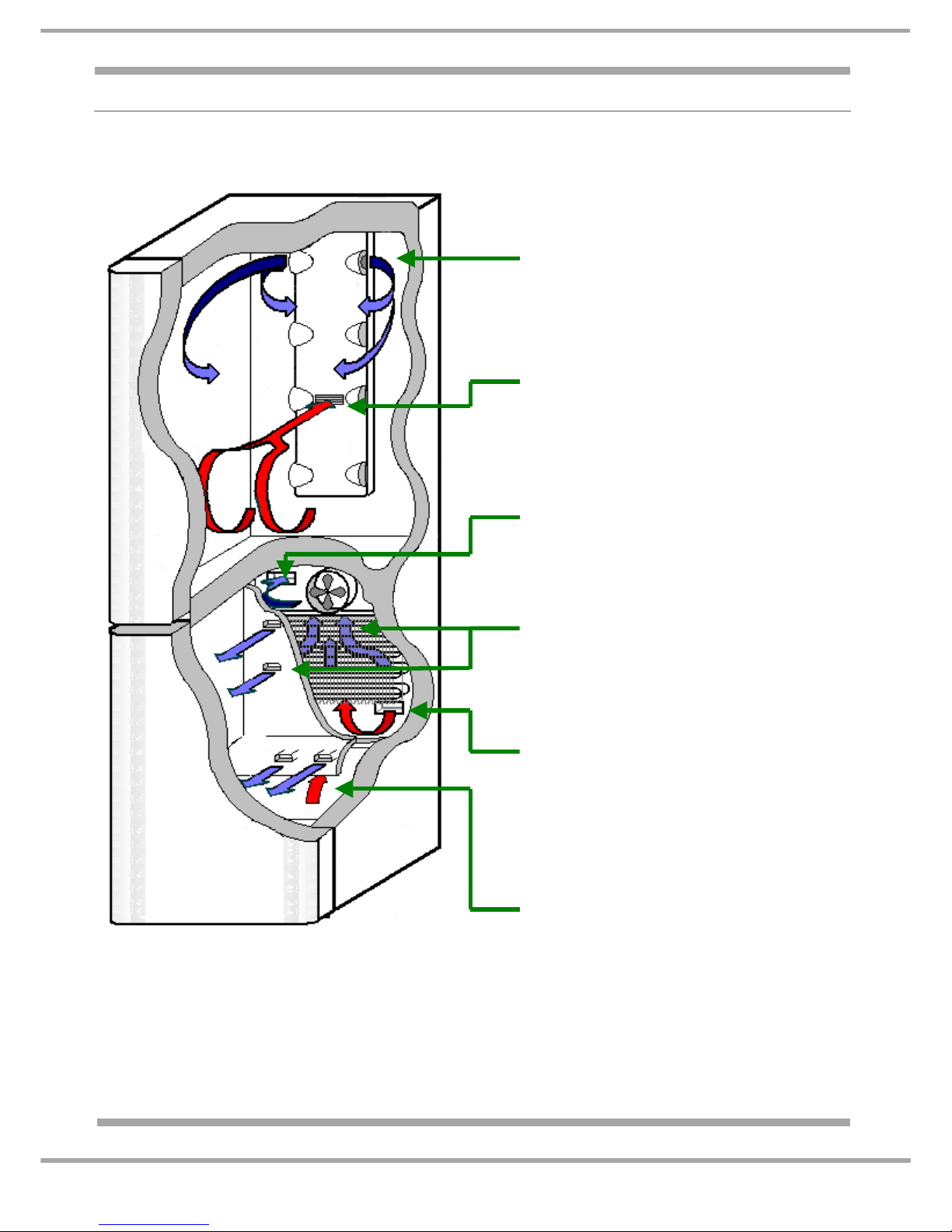
AIR FLOW
Shown through a schematic section of the cabinet
WHEN THE DAMPER (BAFFLE) OPENS,
COLD AIR ENTERS THE FRIDGE VIA
THE INLET PORTS IN THE MULTI-FLOW
UNIT.
NOTE: SOME PORTS ARE
INTENSIONALLY BLOCKED OFF.
WHEN THE DAMPER (BAFFLE) OPENS,
AIR RETURNS TO THE FREEZER
SECTION VIA THE EXHAUST GRILLE IN
THE CENTRE OF THE MULTI-FLOW
UNIT
CIRCULATED AIR IN THE FREEZER
COMPARTMENT IS DRAWN BACK
UNDER THE REAR DUCT PANELTO
THE EVAPORATOR ASSEMBLY.
AIR FLOW RETURNS TO THE FRIDGE
VIA THE INLET DUCTING.
NOTE: THE DAMPER (BAFFLE) IN THE
FRIDGE MULTI FLOW UNIT NEEDS TO
BE IN THE OPEN POSITION FOR THIS
TO HAPPEN.
THE FAN DRAWS AIR THROUGH THE
EVAPORATOR AND BLOWS IT INTO
THE TOP OF THE DUCT PANEL, IT IS
THEN CHANNELED TO THE
INDIVIDUAL FREEZER BASKETS VIA
OUTLET PORTS.
THE EVAPORATOR FAN DRAWS AIR
FLOW FROM THE FRIDGE EXHAUST
BACK THROUGH THE EVAPORATOR.
NOTE: THE DAMPER (BAFFLE) IN
THE FRIDGE MULTI FLOW UNIT
NEEDS TO BE IN THE OPEN
POSITION FOR THIS TO HAPPEN.
Page 19
19 of 36
Indesit Company
Service Manual UK English
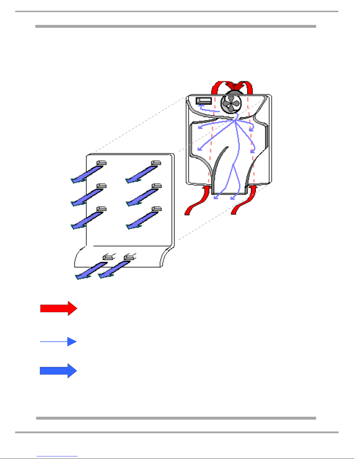
DUCT PANEL AIR FLOW
(Exploded View)
THE ABOVE PROCESS IS REPEATED SO LONG AS THE EVAPORATOR FAN IS RUNNING.
= THE EVAPORATOR FAN DRAWS AIR UNDER AND BEHIND THE REAR DUCT
PANEL AND THROUGH THE EVAPORATOR ASSEMBLY. IT IS THEN BLOWN
BETWEEN THE FRONT AND REAR DUCT PANELS.
= AIR FLOW IS THEN CHANNELLED AND DISTRIBUTED UNIFORMALLY TO
THE OUTLET PORTS OF THE FRONT AIR DUCT.
= AIR FLOW IS DIRECTED TO THE INDIVIDUAL STORAGE DRAWERS.
REAR SECTION
FRONT SECTION
FRONT SECTION
REAR SECTION
Page 20

20 of 36
Indesit Company
Service Manual UK English
POWER / CONTROL MODULE Parameters
(Values stated are for guidance only - may change without notice)
COMPRESSOR OPERATION
continued…
Parameter Values
Stored in the Module
Direct the Appliance
Operations-
Parameters set in the module memory control the
appliance functions.
The minimum and maximum values for temperature are
preset in the module memory. Sensors monitor
temperature and the values are registered in the module.
Where the sensor values are outside the presets a
particular function will start or stop.
Where a sensor fails, open or closed, the appliance
operation will be controlled by time. The timed values for
this are calculated in the module memory.
The power module monitors fridge door opening times and
compressor run times. When the total of the door open and
compressor run times are equal too or exceed the
parameter values set in the memory, a defrost sequence
will be initiated.
Compressor Operation –
There are situations of cooling
demand in which the compressor
remains off.
These are as follows:
Compressor protection: the compressor switches on
once a minimum safety time lag has elapsed since the
last power-off, thereby allowing refrigerant gas
pressure to reach a point of equilibrium in the
refrigerant circuit. The same minimum safety time is
observed in the event of a mains power interruption
(voluntary or involuntary).
Minimum of 8 minutes - In some instances this has
been reported to have been 20 minutes plus.
• This compressor protection strategy is observed only
after the product has been operating continuously for
the number of hours defined in the module memory.
24 hours
• Long periods of activity: if the compressor remains
on for more than a value set in the module memory it is
switched off, even in the presence of a cooling
demand.
254 minutes
• Pause after defrost: at the end of the defrost cycle the
compressor observes a protection time parameterised
in the module memory so that the water formed during
defrost can be completely drained.
12 minutes
Page 21

21 of 36
Indesit Company
Service Manual UK English
POWER/CONTROL MODULE Parameters
(Values stated are for guidance only - may change without notice)
DEFROST AND DRIP TRAY HEATING ELEMENTS
FREEZER FAN OPERATION
FRIDGE LAMP OPERATION
continued…
Defrost and Drip Tray Heating
Elements -
The parameters utilised to start the
defrost cycle are as follows:
• Compressor ON time since the last defrost cycle.
600 minutes
• Duration of doors open condition.
If the door is opened more than 30 minutes, there is a
defrost every 2 hours.
• Enabling Super Freeze.
The defrost cycle is initiated as soon as you start up the
super freeze function. While the super freeze functi on is
enabled there will be a defrost cycle every 2 hours.
The parameters utilised to end the
defrost cycle are as follows:
• Maximum time defrost heater is ON.
32 minutes
Defrost end temperature (freezer evaporator sensor).
+10°C
Freezer Fan Operation -
The freezer fan is managed by the
power module and is switched on/off
after a preset time interval that is
parameterised in the module
memory after a compressor start/
stop.
The defrost procedure is preceded by activation of the fan
and the fridge damper opening for a timed interval that
is parameterised in the module memory.
4 minutes
After the defrost cycle the fan starts after a timed in te rval
following a compressor start, also this interval is
parameterised in the module memory;
12 minutes PLUS 5 minutes
NOTE: This interval is different from the interval
programmed for normal operating conditions.
Fridge Lamp Operation -
A reed switch and a triac on the
power module control the Interior
lamps.
If the door remains open for a timed period that is greater
than the time interval stored in the module memory, the
lamp will start flashing and continue until the door is
closed.
2 minutes
Page 22

22 of 36
Indesit Company
Service Manual UK English
FAULT DIAGNOSIS QUICK GUIDE
SYMPTOM CAUSE ACTION
INTERIOR
LIGHT
FLASHING
• Indicates that the fridge door has
been left open for too long a period,
(over 2 minutes approx.).
• Close fridge door.
• Check the magnet position in the top
of the fridge door cover strip.
• Check the reed switch mounted on
the module.
FRIDGE
TEMPERATURE
WARM
Freezer
temperature
correct
• Fridge door seal not sealing. • Check fridge door seal.
• Fridge baffle is in the closed position. • Check baffle connections and ensure
that the sensor in the return duct is
clear of foam and other debris,
before replacing the baffle assembly.
• Ducting between fridge and freezer
restricted.
• Check for Ice build up around the
inlet and return ducting in the freezer.
• Check for air ingress, ensure the
freezer multiflow is sealing against
evaporator. If the restriction is
caused by foam then remove where
possible.
FREEZER
EVAPORATOR
FAN NOT
RUNNING
• The fan is managed by the power
module and is switched ON/OFF after
a pre-set time interval that is
parameterised in the module memory
after a compressor start/stop.
• (Refer to the 'Power/Control Module
Parameters' on page 21)
• Allow for delay start before
proceeding.
• Check fan assembly.
• Check fan blades are free to rotate.
• Check fan motor is securely clipped
into position.
• Check wiring and connections.
• Defrost cycle enabled. • Advise the customer that the fan will
not run during the defrost cycle.
• Fridge door open. • Close fridge door.
• Check magnet position in top of
fridge door.
• Check reed switch mounted on the
module is OK.
Fridge door open - reed switch contacts
open,
Fridge door closed - reed switch contacts
closed.
FREEZER
WARM
• Door seals not sealing. • Check door seals.
• Evaporator fan not running. • (See above) FREEZER
EVAPORATOR FAN NOT
RUNNING.
• Defrost cycle enabled. • Advise the customer that the freezer
may become warmer during the
defrost cycle.
• Compressor not running • (See next page)
COMPRESSOR NOT RUNNING.
Page 23

23 of 36
Indesit Company
Service Manual UK English
FAULT DIAGNOSIS QUICK GUIDE
SYMPTOM
CAUSE ACTION
COMPRESSOR
NOT RUNNING
(Fridge Interior
Lamp/Lamps
Working)
• Freezer evaporator and air
temperature are correct.
• If the freezer temperature is OK then
advise the customer that the
compressor will start when there is a
demand for cooling.
• Compressor protection is enabled:a. If the appliance is accidentally
switched OFF and switched
immediately back ON.
b. After a mains power cut,
c. Running continuously,
d. Post defrost cycle,
• Compressor protection:
a. Allow the compressor to cool and
the refrigerant to equalise in the
system.
b. As a. above.
c. Check the position of the freezer
air sensor;
Check refrigerant system for leaks
and/or blockages.
d. At the end of the defrost cycle the
compressor observes a protection
time delay parameterised in the
memory, this allows the water
produced during the defrost cycle
to drain away completely.
• Compressor has a humming noise
before the overload switches
compressor OFF.
• Compressor possibly seized or PTC
faulty.
• Compressor Start or Run windings
faulty.
• Check the resistances of the
compressor windings.
Refer to Diagnostic Manual
5407355 for further testing of the
compressor.
• There are situations of cooling demand
in which the compressor remains OFF
• See Control/Power Module
Parameters page 20, Section
headed Compressor Operation.
COMPRESSOR
NOT RUNNING
(Fridge Interior
Lamp/Lamps
Not Working)
• Mains plug fuse blown. • Check fuse rating. If the fuse is of the
correct rating and has blown then
check appliance for reasons.
• Appliance mains cable faulty. • Check the condition of the appliance
mains cable and the connections to
the compressor terminal block.
• Installation fault. • Advise customer of installation fault.
CUSTOMER
COMPLAINING
OF SOUNDS
FROM THE
FREEZER
(Sounds
different
compared with
my previous
fridge freezer)
• The evaporator fan circulating the air in
the freezer compartment may be
heard.
• All the sounds described are quite
normal and mean that the appliance
is functioning correctly.
• Cracking sounds: This is where parts
inside the fridge freezer expand and
contract as they rapidly change
temperature.
• Gurgling sounds: Refrigerant flowing
through the system pipes can produce
gurgling, bubbling, roaring or humming
sounds.
Page 24
24 of 36
Indesit Company
Service Manual UK English
SERVICING & DISMANTLING INSTRUCTIONS
Important Notes for Guidance:
Before commencing any work refer to the Safety Notes at the beginning of this manual.
A. Removing the Fridge Door
1. Remove the contents, food and furniture.
2. Remove the top hinge blanking plug from the top of the fridge door and unclip the door hinge cover
magnet strip.
3. While supporting the fridge door, unscrew and remove the top hinge pin and lift the door from the
centre hinge.
B. Removing the Freezer Door
1. Remove the fridge door as in A1 to A3.
2. While supporting the freezer door, remove the centre hinge assembly.
3. Lift the freezer door enough to release it from the lower hinge pin.
C. Control Panel (housing the Power / Control module)
1. Remove the fridge door as in A1 & A3.
2. Unclip and remove the top hinge cover and the left hand blanking cover from the control panel.
3. Remove the two screws securing the control panel to the cabinet.
4. Pull the control panel forward enough to gain access to the module and wiring harness.
5. Release the wiring from the module.
D. POWER / CONTROL Module
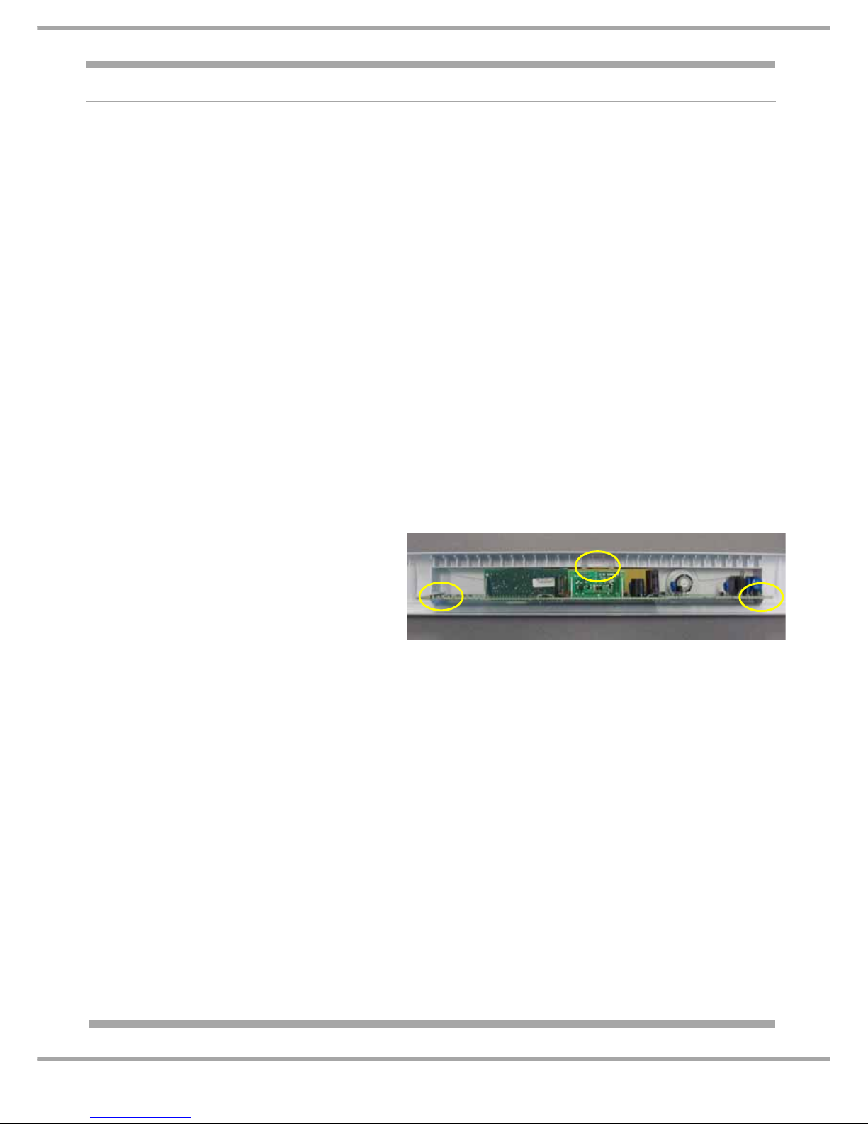
NOTE: - Assemble in the same order starting at position ‘A’ then ‘B’ aligning the control knobs to
the potentiometers mounted on the module and ending with position ‘C’. When assembled check
that the temperature selectors can rotate through all the settings.
E. Door Seals (replaceable)
NOTE: - There is a moulding at the rear of the door seal that locates into a groove in the door liner to
secure it.
1. To replace, ease the seal away from the door liner starting at the middle of one of the sides then work
around the door to release completely. If the seal is a tight fit into the liner, th e liner must be supported
to prevent any damage.
F. Interior Lamps
1. Unclip the lamp cover/s.
2. Unscrew the relevant lamp; the replacement lamp must be of the same rating as the power range
indicated on the cover (e.g. 10W).
G. Fridge Multi-Flow Unit
1. Remove the contents, food and furniture from the fridge compartment.
1. Remove the fridge door and control panel
as in C1 to C5.
2. Set the temperature control knobs to the
“I Care” position.
Unclip the module from the panel.
Start with position
‘A’ then ‘B’ and ending with position ‘C’.
See photo on the right for clip positions.
A
B
C
Page 25
25 of 36
Indesit Company
Service Manual UK English
2. Remove the plastic cover from the interior lamp housing.
3. Unscrew the screws at base of multiflow unit and from the inside of the lamp holder.
4. Pull the base of the multi-flow unit towards you while simultaneously sliding it downwards releasing it
from the top locating lugs.
NOTE: - Withdrawing the multiflow unit may be impeded by the baffle unit mounted to the liner wall
immediately behind the upper section of the multiflow unit.
5. Disconnect the lamp holder and baffle wiring from the connector blocks (See also J2 below).
6. Replace seals as necessary to ensure good sealing.
7. When reassembling, ensure the wiring is not able to foul the baffle or be trapped by the duct moulding.
H. Door Reversal ~ See Page 35
J. Damper (Baffle) Unit (Motorised Type)
1. Remove the Multi-Flow unit as in G1 to G5.
2. Disconnect baffle wiring from the terminal block above the baffle unit. To release the plug depress the
tab on its upper side.
3. Replace seals as necessary to ensure good sealing.
K. Freezer Fan Motor
1. Remove the contents, food and furniture from the freezer compartment.
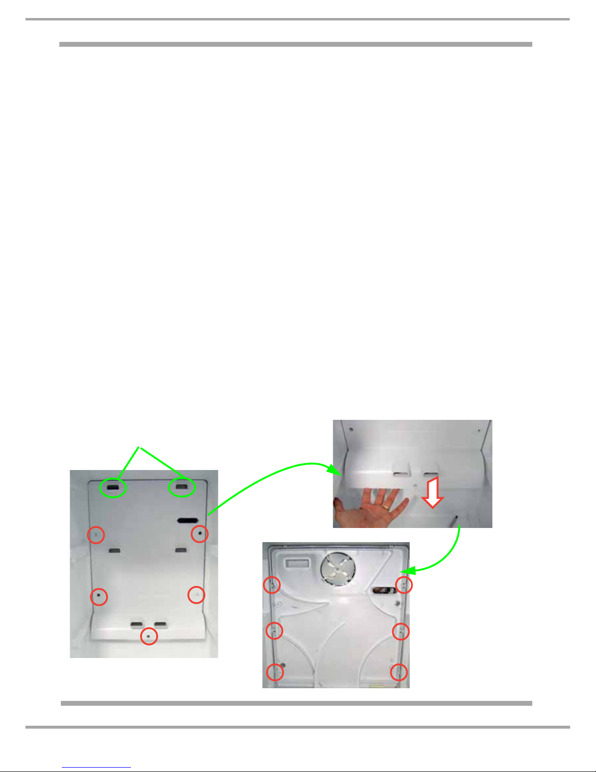
2. Remove the screws from around the edge of the duct cover (See photo 1).
3. Insert a slotted screwdriver into the cover upper vent holes to unclip the cover from the duct
assembly (See photo 1).
4. Pull cover forward and withdraw (See photo 2).
5. With the cover removed, unclip the duct assembly from the sides of the freezer liner and withdraw
assembly complete with fan motor housing (See photo 3.).
6. Disconnect fan wiring from the terminal block.
7. Pull fan impeller off the motor shaft; lay the duct assembly face down so the fan motor bracket is upper
most. Unclip the plastic fan motor bracket to release the fan motor.
Photo 1
Photo 2
Photo 3
Insert a slotted screwdriver into the upper
vents to unclip it from the duct assembly
shown in Photo 3.
Page 26
26 of 36
Indesit Company
Service Manual UK English
PROGRAMMING THE POWER MODULE
The replacement power module is supp lied un-programmed as it is used on oth er model with their own
specific programmes.
The use of an Eeprom is no longer ne cessary. Th e modu le does n ot have th is comp onent and there is
no Eeprom socket for inserting it. The programme file will be stored directly in the microprocessor.
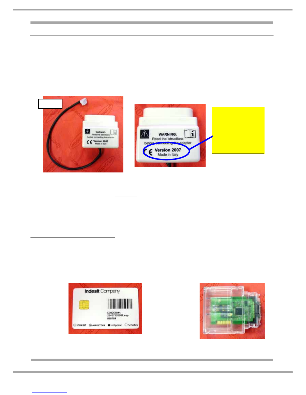
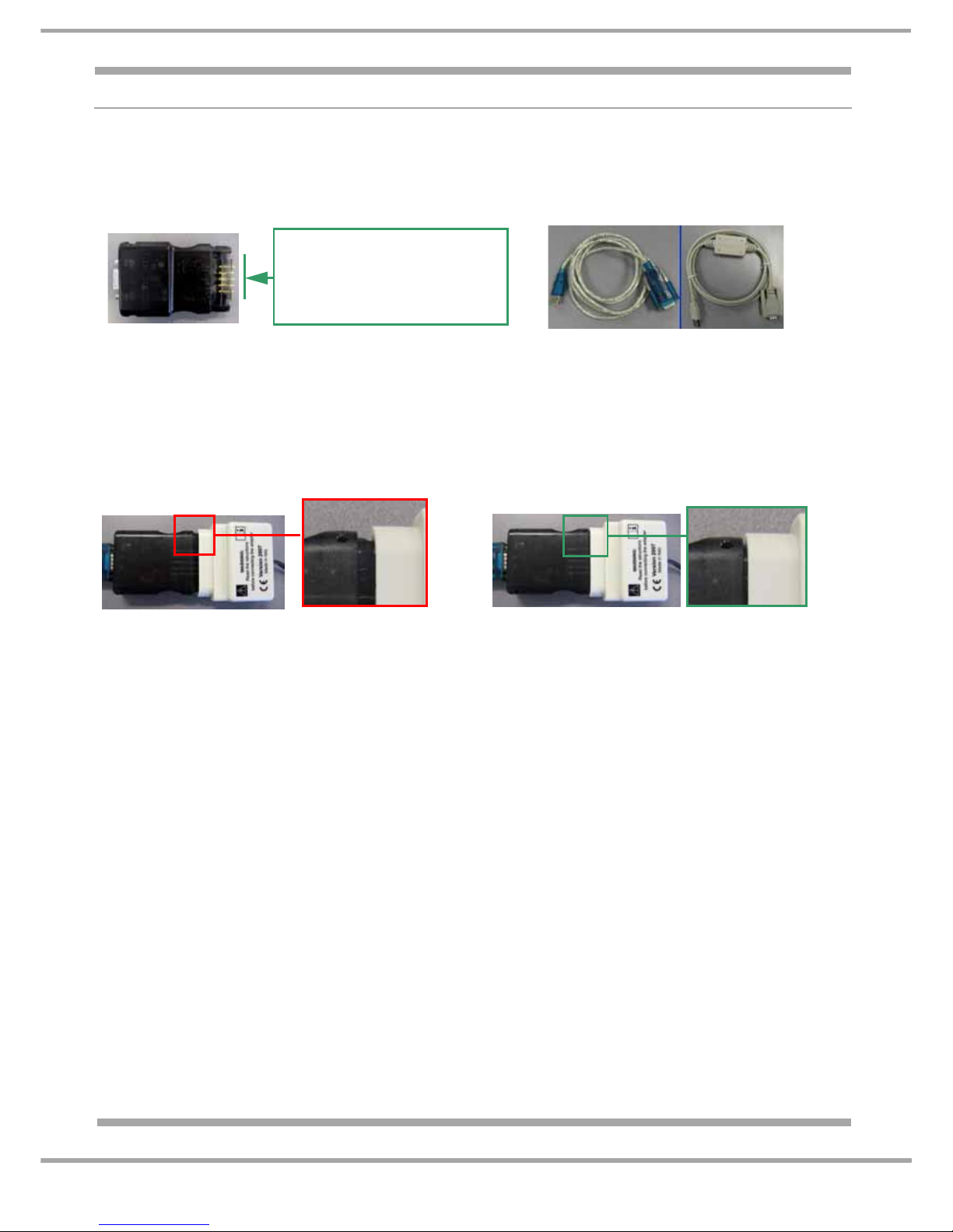
Due to the module being mounted in the top front facia a new adaptor
is necessary to connect the
module. This new adaptor is similar to the earlier low end adaptor, but is compatible with EVOI, EVOII
and New Platform modules. Part No. C00255979.
See photo 1 & 1a below.
The new adaptor can be identified with “Version 2007” printed on the plastic housing.
NOTE: The previous low end adaptor can be identified with “Version 2005” printed on the plastic
housing. “Version 2005” adaptors must not
be connected to New Platform modules.
There are two different methods of programming the module:
INDESIT ENGINEERS ONLY
1. Using a Hand-Held or PC (emit) with the BLACK Hardware Key (to download the programme
file).
Suitably Qualified Persons ONLY
(refer to pages 2 & 3 of the HEALTH & SAFETY section at the
front of this manual before proceeding)
2. Using a Smart Card (which contains the specific programme file) in association with a Smart
Reader for reading the card. See photos 2 & 2a below.
The Smart Card is listed against all relevant models. You will need the following additional
information from the appliance rating plate to identify the correct Smart Card:
Model No., Industrial Code and Serial No.,
Photo 1a
Photo 2
Smart Card
Photo 2a
Smart Card
Reader
Photo 1
Version 2007
compatible with:
EVOI, EVOII &
NEW PLATFORM
modules
Page 27
27 of 36
Indesit Company
Service Manual UK English
PROGRAMMING METHODS EXPLAINED: METHOD 1 - Indesit ENGINEERS ONLY
If the Power Module has been replaced it will require programming using the following method.
The module can be programmed via a Hand-Held or PC (Emit), using a USB lead (Part No.
C00222800), Black Hardware key (Part No. C00115587), Low End Adaptor 2007 (Part No. C00255979
& the Memwriter software. (For more comprehensive information on Memwriter, refer to Manual
C00256775)
1. Disconnect the appliance from the electricity supply.
2. Connect the Low End Adaptor version 2007 to the module.
(See “Connecting the Low End Adaptor” on page 30)
3. Insert the Black Hardware key into the Low End Adaptor. Ensure the Hardware key is correctly
orientated before inserting into the Low End adaptor (there are locating guides on the Hardware key to
assist you). NOTE: The Hardware Key may require firm pressure to fully locate to the Low End
Adaptor. See photo 3 & 3a below.
4. Connect the Hardware key to a Hand-Held or PC (Emit), using the USB lead.
5. Connect the appliance to the electricity supply.
6. Select Memwriter programme.
7. Ensure the correct Valid COM PORT is selected.
8. Ensure the correct Hardware key is selected (Black).
9. Ensure the correct Appliance type is selected (New Platform)
10. Open Com Port (A bright green connection icon will light on screen).
11. Select "Part No." or "Commercial Code" for the search method.
12. Insert the "Part No." or "Commercial Code". (For UK models refer to the relevant Special Notice
if against the Eeprom and/or SmartCard in Partfinder). IMPORTANT: Always use the serial No.
from the rating plate where prompt; this is to ensure you download the correct file version.
13. Click search button.
14. File to download boxes will now display the programme information. It is important to remember
that the actual model No. may not appear, as the programme may be used on other models also.
To confirm the correct file is shown, refer to the relevant parts list in Partfinder.
15. Click download.
If the module has already been programmed with the most updated file a warning box will
appear indicating "ALREADY UPDATED"
16. Disconnect the appliance from the electricity supply.
17. Remove the Low End Adaptor from appliance.
NOTE: When starting Memwriter programme the default search is always Get From Hardware. Only
use "Part No." or "Commercial Code" search when programming a Non-Programmed module.
Not Located
Photo 3
Located
Photo 3a
A Hardware Key Pin Repair
Kit is available which
contains 5 replacement pins
(Part Number C00114723)
Page 28
28 of 36
Indesit Company
Service Manual UK English
PROGRAMMING METHODS EXPLAINED
METHOD 2 - SMARTCARD - SUITABLY QUALIFIED PERSONS ONLY
If the Power Module has been replaced, it will require programming using the following method.
1. Disconnect the appliance from the electricity supply.
2. Connect the Low End Adaptor version 2007 to the module.
(See “Connecting the Low End Adaptor” on page 30)
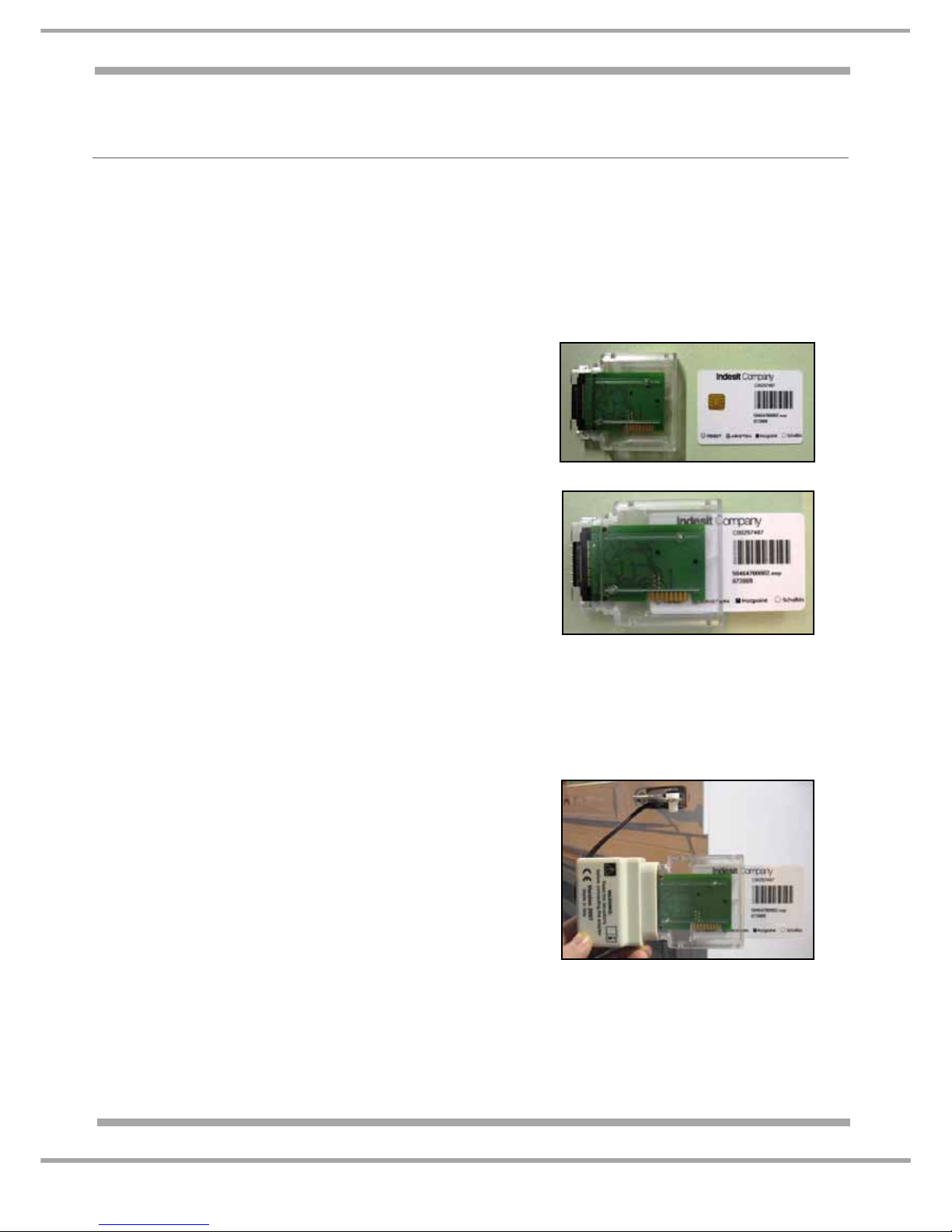
3. Insert the SmartCard into the Card Reader. Care must be taken at this point to ensure that the
Chip on the SmartCard enters & faces the PCB of the reader first. See Photo 4 & 4a.
4. Connect the Smart Card Reader into the Low End
Adaptor. Ensure the Hardware key is correctly
orientated before inserting into the Low End adaptor
(there are locating guides on the Hardware key to
assist you).
NOTE: The Hardware Key may require firm pressure
to fully connect to the Low End Adaptor.- See photo 5.
5. Connect the appliance to the Electrical supply,
The LED's on the Smart Card Reader will light in this
sequence:
a. Red ON: Good Communication between Smart Card
Reader & Card. See also Note 1 below.
b. Red OFF; Green Blinking: Download taking place.
c. At end, Green ON = Download OK, module
programmed, Red ON = Download NOT OK.
6. Disconnect the appliance from the electricity supply.
7. Remove the Smart Card, Reader and Low End
Adaptor from appliance.
8. Reassemble and make appliance safe.
9. Connect the appliance to the Electrical supply.
Note 1.
a If the Red LED is flashing SLOWLY, and a smartcard
is inserted, check for the following:
• Blank/erased smartcard (previously used),
• Incorrectly inserted smartcard (check orientation of
smartcard chip)
• Poor connection between the smartcard and
smartcard reader.
Refer to photo 4 - 4a above.
bIf the Red LED is flashing RAPIDLY, check for the
following:
• Ensure a smartcard has been inserted into the
smartcard reader,
• Ensure the smartcard has been fully inserted?
Refer to photo 4a above.
Photo 4
Photo 4a
Photo 5
Page 29
Indesit Company
29 of 36
Service Manual UK English
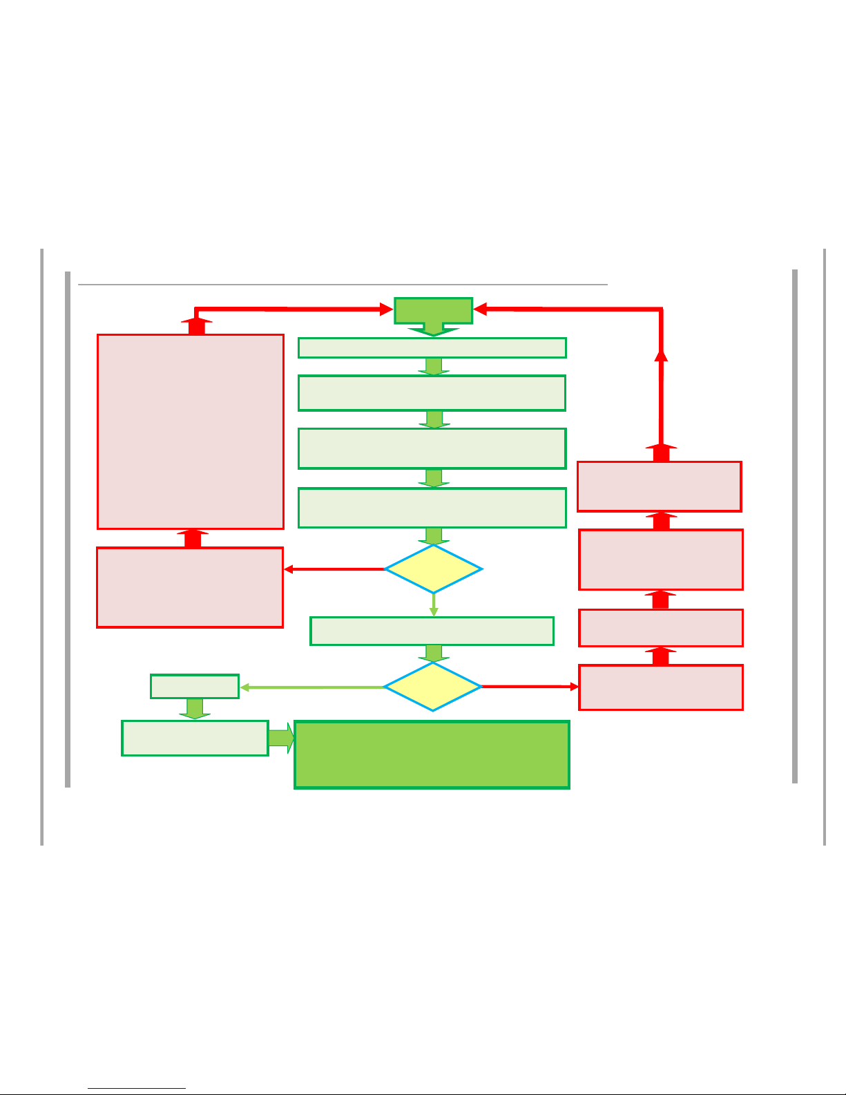
SMARTCARD PROGRAMMING PROCEDURE - FLOWCHART
DISCONNECT(unplug)THEAPPLIANCEFROMTHEELECTRICALSUPPLY(grid)
INSERTAVALIDSMARTCARD,RELATINGTOTHEMODEL&MAINPOWER
MODULE(board)TOBEPROGRAMMED,INTOTHESMARTCARDREADER
INSERTTHESMARTCARDREADERINTOEITHERTHESERIALPORTOFTHE
POWERMODULE(BOARD)ORINTOTHELOWENDADAPTOR(Version2007)
REͲCONNECTTHEAPPLIANCETOTHEELECTRICALSUPPLY(GRID).ASTATIC
REDLEDWILLLIGHTUPTOSIGNALTHATTHESMARTCARDREADERIS
CONNECTIONISVERIFIED(OK)DOWNLOADNOWINPROGRESS
THEPOWERMODULEISNOWPROGRAMMED.
DISCONNECT(unplug)THEAPPLIANCEFROMTHEELECTRICALSUPPLY(grid)
REMOVETHESMARTCARDREADER
(DISCONNECTTHELOWENDADAPTORWHEREUSED)
IFTHERED LEDISFLASHING
x COMMUNICATIONPROBLEM
x SMARTCARDINVALID/ERASED
DISCONNECT(unplug)THEAPPLIANCEFROMTHE
ELECTRICALSUPPLY(grid)
DOWNLOADOK
THESMARTCARDCONTENTWILLBE
AUTOMATICALLYERASED
IFTHE RED LEDISSTATIC(fixed):
x DOWNLOADHASFAILED(KO)
IFTHEDOWNLOADFAILEDTHESMARTCARD
WOULDNOTHAVEBEENERASED
DISCONNECTTHESMARTCARDREADER
FROMTHEAPPLIANCEANDTHE
SMARTCARDFROMTHESMARTCARD
READER
RESOLVETHEPROBLEM:
FURTHERDIAGNOSTICSMAYBEREQUIRED
ONTHEAPPLIANCE
NO
YES
NO
YES
ISTHE
GREENLED
FLASHING?
ISTHE
GREENLED
STATIC?
START
DISCONNECTTHESMARTCARDREADERFROMTHE
APPLIANCEANDTHESMARTCARDFROMTHE
SMARTCARDREADERANDACTIONBELOW:
IftheREDLEDwasflashingSLOWLY,anda
smartcardwasinserted,checkforthefollowing:
x Invalid/erasedsmartcard(previouslyused)
Discardtheinvalidsmartcard,
x Incorrectlyinsertedsmartcard,
(checkorientationof
the
smartcardchip)
x Poorconnectionbetweenthesmartcardand
smartcardreader.
IftheREDLEDwasflashingRAPIDLY,checkforthe
following:
x Ensureasmartcardwasinsertedintothe
smartcardreader,
x Ensurethesmartcardwasfullyinserted?
Page 30
30 of 36
Indesit Company
Service Manual UK English
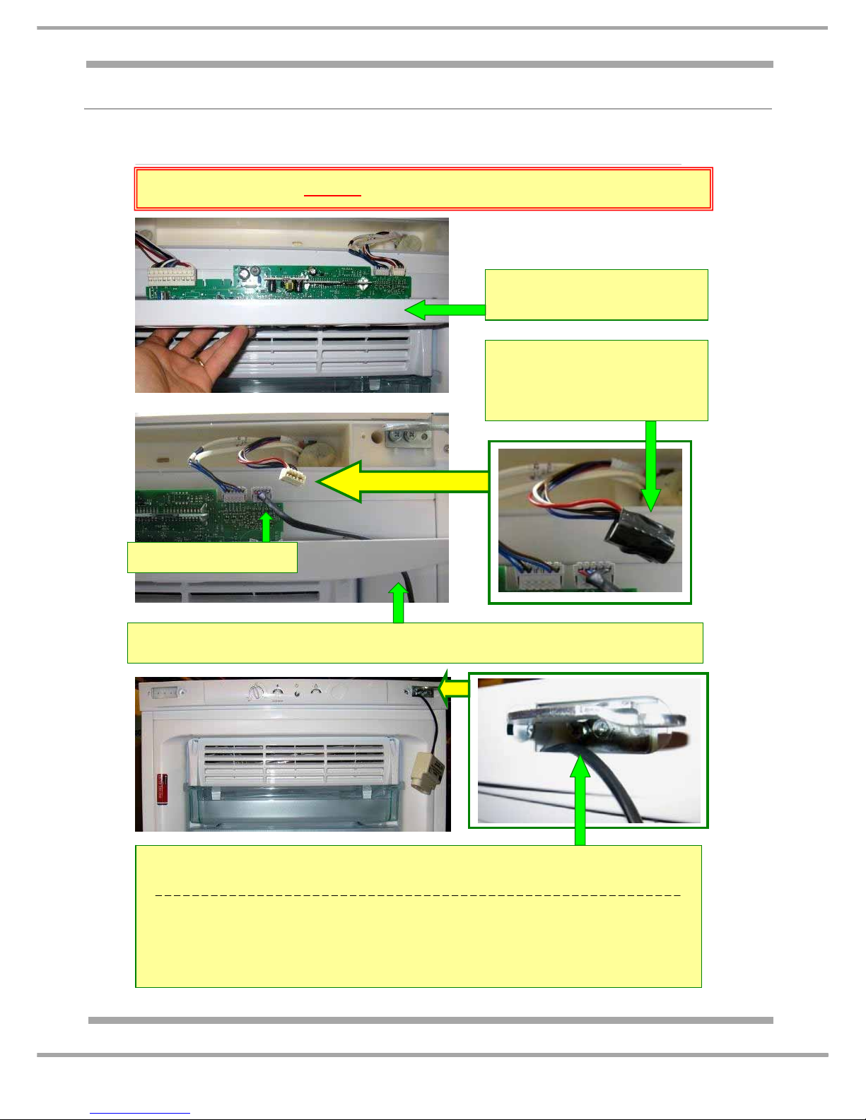
CONNECTING THE LOW END ADAPTOR - 2007 Version
The photos below may show a differnet model to the one you are programming but the Low End Adaptor
connection is the same.
Step 1 - Lower the control panel to
access the module and wiring.
Step 2 - Disconnect and insulate
the IDC connector block from
module edge connection E3. This
will prevent it from shorting on the
module whilst disconnected.
Step 4 - Temporary reassemble the control panel before plugging the appliance in.
To prevent damage to the harness of the adaptor key, route it under the screw fixing post of the
control panel.
NOTE: Unplug the appliance from the mains supply before disconnecting the adaptor key. The
original IDC connector block, which you disconnected and taped up earlier in Step 2 above,
does not need to be reconnected. This connection was for production purposes only and has no
other function. Therefore keep the edge connector insulated and safely positioned in the control
housing.
EDGE CONNECTION E3
Step 3 - Route the adaptor key through top right hinge opening in the control panel
and connect to edge connection E3 on the module.
BEFORE PROCEEDING UNPLUG THE APPLIANCE FROM THE ELECTRICITY SUPPLY
Photo 1
Photo 2
Photo 3
Page 31
31 of 36
Indesit Company
Service Manual UK English
WIRING CONNECTION CHART
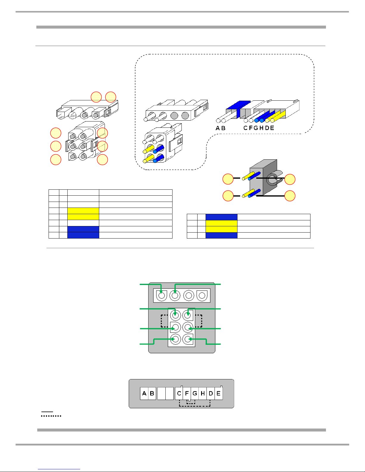
A ~ WHITE Freezer Evapora tor Fan Motor
B ~ WHITE Freezer Evapora tor Fan Motor
C ~ WHITE Evaporator Defrost Heater
D ~ YELLOW Thermal Fuse
E ~ YELLOW Thermal Fuse
F ~ WHITE Evaporator Defrost Heater
G ~ BLUE Thermal Fuse
H ~ BLUE Thermal Fuse
J ~ BLUE To Terminal Block G
K ~ YELLOW To Terminal Block D
L ~ YELLOW To Terminal Block E
M ~ BLUE To Terminal Block H
DEFROST HEATER
AND
THERMAL FUSE
CONNECTION PLUG
(FRONT VIEW – PIN SIDE)
DEFROST HEATER
AND
THERMAL FUSE
CONNECTION PLUG
(REAR VIEW – WIRE SIDE)
ALTERNATIVE
DEFROST HEATER
AND
THERMAL FUSE
CONNECTION PLUG
(REAR VIEW – WIRE SIDE)
THERMAL FUSE
(CLIPPED TO EVAPORATOR)
DEFROST HEATER
AND
THERMAL FUSE
CONNECTION SOCKET
ALTERNATIVE
CONNECTION SOCKET
From ~ Power Module E1 terminal 8
To ~ Freezer Evaporator Fan
From ~ Gutter Heater (foamed in)
To ~ Evaporator Defrost Heater
From ~ Thermal Fuse (internally linked
to socket pin above to Defrost Heater)
From ~ Power Module E1 terminal 6
To ~ Thermal Fuse
From ~ Gutter Heater (foamed in)
To ~ Evaporator Defrost Heater
From ~ Power Module E1 terminal 1
To ~ Freezer Evaporator Fan
From ~ Thermal Fuse (internally linked
to socket pin above to Defrost Heater)
From ~ Power Module E1 terminal 2
To ~ Thermal Fuse
C
D
E
F
G
H
BA
K
L
J
M
A B
F
G
H
C
D
E
KEY
= Indicates Internal Links
Page 32
32 of 36
Indesit Company
Service Manual UK English
POWER / CONTROL MODULE EDGE CONNECTIONS
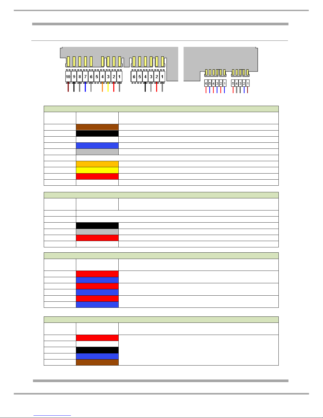
E 1 – TERMINAL CONNECTIONS
TERMINAL
No.
WIRE COLOUR COMPONENT
10
BROWN
LINE (LIVE)
9
BLACK
COMPRESSOR OVERLOAD (COMMON)
8
WHITE
EVAPORATOR FAN MOTOR
7
BLUE
NEUTRAL
6
GREY
THERMAL FUSE
5 NOT USED
4
ORANGE
FRIDGE INTERIOR LAMP
3
YELLOW
FRIDGE INTERIOR LAMP
2
RED
THERMAL FUSE
1
WHITE
EVAPORATOR FAN MOTOR
E 2 – TERMINAL CONNECTIONS
TERMINAL
No.
WIRE COLOUR COMPONENT
6 NOT USED
5 NOT USED
4
BLACK
FRIDGE DAMPER (BAFFLE)
3
GREY
FRIDGE DAMPER (BAFFLE)
2
RED
FRIDGE DAMPER (BAFFLE)
1
WHITE
FRIDGE DAMPER (BAFFLE)
E 4 – IDC CONNECTIONS
TERMINAL
No.
WIRE COLOUR COMPONENT
6
RED
FREEZER AIR THERMISTOR SENSOR (black sleeve)
5
BLUE
4
RED
FRIDGE AIR THERMISTOR SENSOR (red sleeve)
3
BLUE
2
RED
FREEZER EVAPORATOR THERMISTOR SENSOR
1
BLUE
E 3 – IDC CONNECTIONS
TERMINAL
No.
WIRE COLOUR COMPONENT
5
RED
FLY LEAD/HARNESS TO COMPRESSOR COMPARTMENT.
THIS HARNESS IS FOR PRODUCTION USE ONLY.
DO NOT CONNECT OR USE THE FLY END OF
THIS HARNESS
4
WHITE
3
BLACK
2
BLUE
1
BROWN
E 1 E 2
E 3 E 4
Page 33
Indesit Company
33 of 36
Service Manual UK English
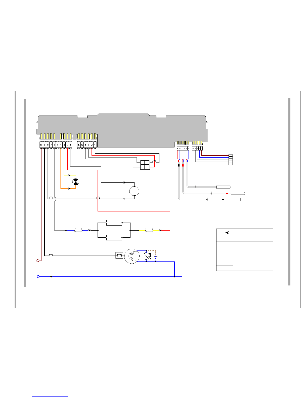
THEORETICAL WIRING DIAGRAM
SOLDERED SIDE
OF
POWER CONTROL MODULE
E3 E4
E2
E1
FREEZER EVAPORATOR SENSOR
FRIDGE AIR SENSOR
FREEZER AIR SENSOR
EVAPORATOR
FAN MOTOR
FRIDGE DAMPER
(baffle)
FRIDGE
INTERIOR
LAMP
THERMAL
FUSE
THERMAL
FUSE
COMPRESSOR
OVERLOAD
CAPACITOR
(if fitted)
EVAPORATOR
DEFROST HEATER
GUTTER HEATER
FLY LEAD/HARNESS TO
COMPRESSOR COMPARTMENT.
THIS HARNESS IS FOR
PRODUCTION USE ONLY.
DO NOT CONNECT OR USE THE
FLY END OF THIS HARNESS
N
L
R2
R1
A
B
C ~ D
E
H
G ~ F
CONNECTORBLOCK
REFERENCES
A
SEEWIRING
CONNECTIONCHART
(page31)
B
C~D
E
G~F
H
Page 34

34 of 36
Indesit Company
Service Manual UK English
THERMISTOR SENSOR LOCATIONS
Three sensors are used in these models, the approximate position is as follows: -
1. Freezer Air Sensor - Located on the compressor step, behind the duct mounting on the right.
2. Freezer Evaporator Sensor - Located in the top right corner of the freezer evaporator.
3. Fridge Air Sensor - Located in the return duct behind the fridge multi-flow unit.
SENSOR RESISTANCE TABLE (Ω)
Temperature (°C) Resistance (kΩ)
-30 175
-25 129.2
-20 96.3
-15 72.5
-10 55
-5 42.1
032.5
525.3
10 19.8
15 15.6
20 12.4
25 10
30 8
35 6.5
40 5.3
45 4.3
50 3.6
55 2.9
60 2.4
65 2
70 1.7
Page 35
35 of 36
Indesit Company
Service Manual UK English
DOOR REVERSAL
Important Notes for Guidance:
Before commencing any work refer to the Safety Notes at the beginning of this manual.
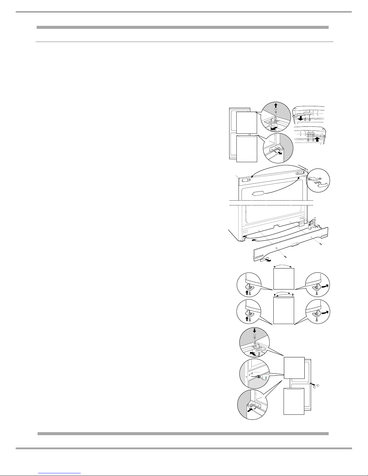
Read the instructions below fully and refer to the diagrams on the right before carrying out the door reversal.
Note: Before commencing the door reversal, you will require the left door stops and centre hinge
blanking plugs normally supplied loose with the literature pack that comes with the appliance.
If the door stops are not available then they will need to be ordered before proceeding.
A: Reversing the Top Hinge
Remove the top hinge-blanking plug from the top of the fridge door.
Unclip the door hinge cover magnet strip. While supporting the
fridge door, unscrew and remove the top hinge pin and lift the door
from the centre hinge (Fig. 1a).
While supporting the freezer door remove the centre hinge and lift
the door from the bottom hinge pin (Fig. 1b).
Remove the upper door hinge, invert and transfer it over to the
other side. The original fixing screws are reused to
refit it (Fig. 1c).
Remove the hinge blanking covers from the control panel and
remove the top hinge, invert and transfer them over to the other
side. The original fixing screws are reused to refit it (Fig. 2).
B: Front Base Moulding (Plinth)
Unscrew the two front screws securing the plinth to the base and
remove plinth. Remove the lower hinge and slide down the fixing
plate, transfer them both to the left hand side. The hinge pin also
needs to be transferred to the left pre-threaded hole (Fig. 3).
Before the plinth is screwed back in place, cut out the pre marked
blanking plate on the left side and use the blanking plate supplied
over to the right side (Fig. 3).
C: Reversing the Top Hinge Bushes and Door Stops
Remove the bottom right hand door stops and fit the left hand door
stops (supplied with the appliance) into the bottom left hand side of
both doors. Locate the door stop peg and secure in place with the
original self-tapping screw (Fig. 4).
Transfer the top blanking plug to the right side of the fridge door.
Transfer the hinge bush and blanking plug over on the freezer door
(Fig. 4).
D: Top Hinge Pin and Door Assembly
If the holes are not present on the left hand side for the centre
hinge, carefully position and drill two 3 mm pilot holes guided by the
indented markings on the centre transom. Ensure the drill bit does
not run too deeply into the appliance (Fig. 5a).
Fit the blanking plugs provided with the appliance into the right
hand two centre hinge holes that are now vacant (Fig. 5b).
Place the freezer door onto the bottom hinge pin.
While supporting the door screw the centre hinge into position
(Fig. 5c).
Place the fridge door onto the centre hinge pin and align it with the
top hinge assembly and screw the top hinge pin in. Refit the hinge
blanking plug and the door hinge cover magnet strip to the fridge
door, noting that the cut-out end corresponds with the hinge (Fig.
5d). Finally check the door operation.
3
mm
a
b
c
d
a
b
c
Fig. 1
Fig. 2
Fig. 3
Fig. 4
Fig. 5
Page 36

36 of 36
Indesit Company
Service Manual UK English
 Loading...