

Hotpoint FF187EA, FF187EG, FF187EK, FF187EP, FF187EPL Service Information
...
Indesit Company UK Ltd
© 2009 Reg. Office: Peterborough PE2 9JB Registered in London: 106725
Service
Information
HOTPOINT
Freestanding
Frost Free
Fridge Freezers
(Version 2)
Refer to Insert below
Models Comm.
Covered Code
FF187EA 40729
FF187EG 39780
FF187EK 53950
FF187EP 39775
FF187EPL 53947
FF200EA 40733
FF200EG 40732
FF200EX 43503
FF200EK 53952
FF200EP 39777
FF200EPL 53949
IMPORTANT
THERE ARE TWO VERSIONS OF THE
ABOVE LISTED MODELS. TO IDENTIFY THE
CORRECT VERSION AND SERVICE
MANUAL SEE BELOW OR Page 5 FOR A
MORE DETAILED EXPLANATION:
VERSION 1 ~
THE POWER MODULE IS MOUNTED AT THE
REAR OF THE APPLIANCE ABOVE THE
COMPRESSOR COMPARTMENT.
VERSION 2 ~
THE POWER MODULE IS MOUNTED IN THE
CONTROL PANEL ONLY, THERE IS NO
REAR MOUNTED MODULE.
FOR VERSION 1 MODELS ~ REFER TO
SERVICE MANUAL 5407327
5407423 Issue 1 Feb. 2009

2 of 36
Service Manual UK
Indesit Company
English
HEALTH AND SAFETY
For the servicing of refrigeration products, containing Isobutane R600a refrigerant.
These instructions are in addition to any other Company procedures already published.
Published primarily for Indesit Company engineers working in the UK or Southern Ireland, for
which these instructions are MANDATORY.
1. Only engineers who have been trained on the safe handling of Isobutane R600a refrigerant are
authorised to transport, store or carry out system repairs.
2. This manual is not intended as a comprehensive repair/maintenance guide to the appliance.
3. Must only be used by suitably qualified persons having technical competence, applicable product
knowledge, suitable tools and test equipment.
4. Servicing of electrical appliances must be undertaken with the appliance disconnected (unplugged
from the electrical supply).
5. Servicing must be preceded by earth continuity and insulation checks, plus refrigerant leak
detection.
6. Personal safety precautions must be taken to protect against accidents caused by sharp edges on
metal and plastic parts.
7. After servicing, the appliance must be rechecked for electrical safety.
8. Smoking, naked flames, or operating gas and/or electrical equipment (including cordless power
tools) are forbidden within the storage area, working area and vehicles used to transport Isobutane.
9. The carrying case for the scales and refrigerant must display a red flammability label
Part No. 8100063 that should be visible and readable at all times.
10. The vehicle and storage area must be ventilated as far as is reasonably practicable and the
aluminium case kept out of direct sunlight. The storage temperature of Isobutane should not exceed
50°C.
11. The vehicle transporting Isobutane (R600a) refrigerant must display a Red Flammable Gas warning
sticker (Part No. 8100063).
12. Engineers should not wear clothe s that are liabl e to cause static discharge ('electrostatic sparking').
13. Avoid working in small rooms.
14. Do not work in cellars.
15. Whenever possible move the applia nce into a larger open ar ea away from possible igni tion sources.
16. Request the customer to turn off all other electrical and gas appliances in the near vicinity of the
repair and note that it is done.
Customers should be advised to restrict activity within the near vicinity for a short time.
17. Isobutane refrigerant must be vented to atmosphere, (outside of the premises e.g. via open window
through the clear plastic hose supplied).
18. Isobutane is heavier than air and must not be vented within 3 metres of the following: sewer cover,
cellar, drain or any similar construction lower than ground level, boiler air inlet/outlet, or near any
possible source of ignition.
continued...

3 of 36
Indesit Company
Service Manual UK English
HEALTH AND SAFETY
19. Working with a naked flame i.e. soldering or brazing is forbidden. Unless otherwise stated,
pipework connections must only be made using the Lokring coupling system.
20. Electronic leak detectors with high voltage tips must NOT be used with any Isobutane (R600a).
21. All equipment used for this activity must be checked re gularly and maintained in a safe working
condition; parts must be replaced as required.
Information Regarding Isobutane Canisters
1. The maximum quantity of Isobutane an engineer should hold or store at any one time is two 1kg
net aluminium canisters, supplied individu ally as Part No. 2602600.
2. Canisters must be stored inside the aluminium case with the weighing scales for protection from
possible damage and heat. The aluminium case must NEVER be placed next to a heat source or
in direct sunlight.
3. Isobutane must only be dispensed to the applia nce fr om the 1kg n et alumini um canister p laced in
an upright position on the weighing scales provided.
4. All used canisters must be a returned as scrap and therefore, left out for the driver to collect and
return for disposal.
5. Canisters must not be punctured or the internal valve damaged.
6. Before storing the canister it must have the extr action tap valv e removed an d the internal va lve of
the canister checked for leakage using leak detector (Leak Detector: Part No. 5700043).
7. All used canisters and those found to be leaking should be exhausted to atmosphere to ensure
they are emptied completely. Refer to the following paragraph.
8. Refit the extraction tap if necessary, open the tap and then invert the canister.
This must be done outside in open air away from buildings and ignition sources and complying with
Item 18 on previous page.
4 of 36
Service Manual UK
Indesit Company
English
CONTENTS
Health and Safety . . . . . . . . . . . . . . . . . . . . . . . . . . . . . . . . . . . . . . . . . . . . . . . . . . . . . . . . . 2 - 3
Index & Serial Number / Product Identity . . . . . . . . . . . . . . . . . . . . . . . . . . . . . . . . . . . . . . . . .4
Introduction . . . . . . . . . . . . . . . . . . . . . . . . . . . . . . . . . . . . . . . . . . . . . . . . . . . . . . . . . . . . . . 5 - 6
Specifications . . . . . . . . . . . . . . . . . . . . . . . . . . . . . . . . . . . . . . . . . . . . . . . . . . . . . . . . . . . . 7 - 8
Product Description with Image. . . . . . . . . . . . . . . . . . . . . . . . . . . . . . . . . . . . . . . . . . . . . 9 - 10
Component Fuction. . . . . . . . . . . . . . . . . . . . . . . . . . . . . . . . . . . . . . . . . . . . . . . . . . . . . . 11 - 12
Alarm Conditions. . . . . . . . . . . . . . . . . . . . . . . . . . . . . . . . . . . . . . . . . . . . . . . . . . . . . . . . . . . .12
Auto-Test & Fault Conditions. . . . . . . . . . . . . . . . . . . . . . . . . . . . . . . . . . . . . . . . . . . . . . 13 - 14
Explanation of Auto-Test Codes . . . . . . . . . . . . . . . . . . . . . . . . . . . . . . . . . . . . . . . . . . . 15 - 17
Airflow . . . . . . . . . . . . . . . . . . . . . . . . . . . . . . . . . . . . . . . . . . . . . . . . . . . . . . . . . . . . . . . . 18 - 19
Power / Control Module Parameters . . . . . . . . . . . . . . . . . . . . . . . . . . . . . . . . . . . . . . . . 20 - 21
Fault Diagnosis Quick guide . . . . . . . . . . . . . . . . . . . . . . . . . . . . . . . . . . . . . . . . . . . . . . 22 - 23
Servicing & Dismantling Instructions . . . . . . . . . . . . . . . . . . . . . . . . . . . . . . . . . . . . . . . 24 - 25
Programming the Module. . . . . . . . . . . . . . . . . . . . . . . . . . . . . . . . . . . . . . . . . . . . . . . . . 26 - 30
Wiring Connection Information . . . . . . . . . . . . . . . . . . . . . . . . . . . . . . . . . . . . . . . . . . . . 31 - 32
Theoretical Wiring Diagram . . . . . . . . . . . . . . . . . . . . . . . . . . . . . . . . . . . . . . . . . . . . . . . . . . .33
Thermistor Sensor Information . . . . . . . . . . . . . . . . . . . . . . . . . . . . . . . . . . . . . . . . . . . . . . . .34
Door Reversal Instructions. . . . . . . . . . . . . . . . . . . . . . . . . . . . . . . . . . . . . . . . . . . . . . . . . . . .35
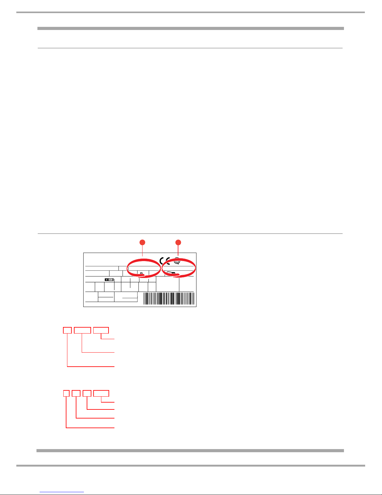
PRODUCT IDENTITY
Mod. - - - - - -
TI
Cod.
93139180000 S/N 704211801
220 - 240 V- 50 Hz 150 W
W
Fuse
A
Max 15 w
Total
Gross
Bruto
Brut
Compr.
Kompr.
Syst.
R134 a
kg 0,090
Gross
Bruto
Brut
340
Net
Util
Utile
Gross
Bruto
Brut
Freez. Capac
Poder de Cong
75
Made in - - - - 13918
Test
P.S-I.
Pressure
HIGH-235
LOW 140
kg/24 h
4,0
Class
Clase
N
Classe
1
2
Example
1 Industrial Code:
93 13918 0000
0000 original production
Commercial Code*
Factory of origin
2 Serial Number:
704 1801
Build number that day, e.g. 1801th built
Day of manufacture, e.g. 21
st
of month
Month of manufacture, e.g. April
21
Year of manufacture, e.g. 2007
*Vital for correct model information and system identification
Other numbers denote major production changes
5 of 36
Indesit Company
Service Manual UK English
MODEL VERSION IDENTIFICATION
The models included in this publication are 1870 & 2000 mm high no-frost fridge freezers that were
introduced in Jan 2008.
There are two versions of the above range of models that share the same model number and commercial
code. The versions can be identified by the serial number on the rating plate behind the bottom drawer on
the rear wall and/or by the power module position.
NOTE ~ If the first three digits of the serial number commence between 710or 801 you must confirm the
location of the power module to positively identify the model version.
See version descriptions and photos below:
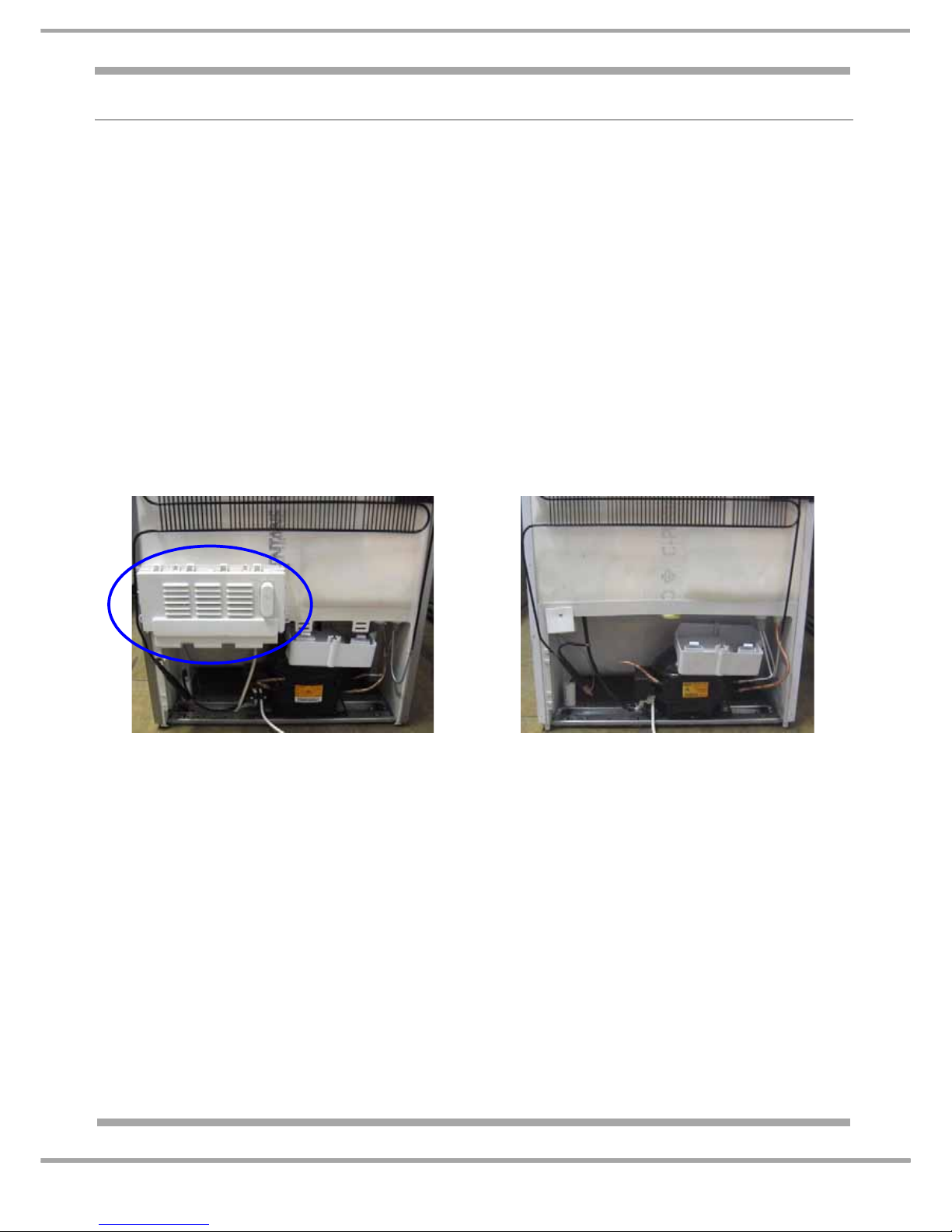
VERSION 1: Refer to Service Manual 5407327 (C00221355) See photo below.
Models produced on or before serial number 801019999.
The power module is mounted at the rear of the appliance above the compressor compartment.
VERSION 2: Refer to this Service Manual
Models commencing with serial number 801020001 See photo below.
The power module is mounted in the top facia (control panel) of the appliance.
For banding and colour information, refer to the Front Cover and/or Specifications page.
VERSION 1:
The power module is mounted at the rear of the
appliance above the compressor compartment
VERSION 2:
The power module has been re-located and is
mounted in the top front facia (control panel).

6 of 36
Service Manual UK
Indesit Company
English
MODEL INTRODUCTION
All models are similar with regard to the furniture design, but there are variations for energy consumption
and exterior colour.
Model FF187E interior:
The interior of the fridge has glass shelves, chromed steel wine rack and two salad bins with a glass cover.
The door has a bottle shelf with retainer, dairy shelf with a lid and one commodity shelf.
The freezer section has four drawers of varying sizes, the lower two drawers have ice cube compartments
inserted in the top of the drawer fronts.
Model FF200E interior:
The interior of the fridge has glass shelves, chromed steel wine rack, fresh box (chiller compartment) and
one full width salad bin with a glass cover. The door has a deep bottle shelf with retainer, dairy shelf with a
lid and one commodity shelf. The freezer section has four drawers of varying sizes, the lower two drawers
have ice cube compartments inserted in the top of the drawer fronts.
The electronic thermostat and LED interface are all part of the power module mounted in the top facia of the
appliance; The fridge and freezer temperature settings are adjusted by operating the control knob s mounted
in the top facia. All functions are monitored and actioned by the power module mounted in the top facia of
the appliance. The fridge baffle is of a motorised type, mounted in the multi-flow unit. The fridge temperatu re
is monitored by a sensor mounted in the return ducting behind the fridge multiflow unit.
The fridge and freezer temperatures are monitored by sensors located in the following locations:
1. Fridge Sensor ~ mounted in the return duct behind the fridge multiflow unit;
2. Freezer Air Sensor ~ mounted in the lower right side of the freezer cabinet liner;
3. Freezer Evaporator Sensor ~ inserted into the top right of the evaporator.
The sensors (thermistors) are not replaceable because they are for the most part foamed behind the liner
where they are not affected by moisture. The sensors are double insulated and in the unlikely event of
failure a section of the power module is programmed to respond and control the functions on a timed basis
from there on in.
The appliance is "no-frost" design (Full Frost-Free) so defrosting is automatic.
All models have rear wheels located in the compressor base plate with adjustable feet fitted at the front.
Doors are reversible, but do require a T20 Torx key to remove the plinth / kick strip.
The climate class is SN / ST signifying that it is designed to operate in ambient temperatures between
+10°C to +38°C. As with many refrigeration appliances, it is important that it is installed and operated within
the recommended ambient temperature range and that there is adequate ventilation.
ANTI-BACTERIA (Hygiene Control)
Some models have anti-bacteria protection (hygiene control) - built in protection for life of the product. Food
safety is becoming increasingly important to consumers with more and more cases of food poisoning.
The hygiene control is built into the plastic of the fridge interior during manufacture so it cannot wash or
wear out. It provides permanent protection against bacteria as it reduces on contact the spread of food
poisoning bacteria, which can cause contamination and odour.
It gives extra hygiene reassurance as it kills or inhibits the growth of any bacteria, which may come into
contact with the interior surfaces of the fridge.
The anti-bacteria protection is approved safe for use in food contact applications by the European Scientific
Committee for Food and has proven safe over many in personal care and household cleaning
products.products.
7 of 36
Indesit Company
Service Manual UK English
SPECIFICATIONS
GENERAL:
Manufactured in: UK (76)
Appliance Type: Freestanding Fridge Freezer
Static / No-Frost: No-Frost
Doors Hinging - Right Hand
Reversible: Yes
Plug/Cable: UK/ 1.6M
FF187E FF200E
Energy Class A” “A”
Power Consumption kWh/24hr: 0.95 0.99
Annual Consumption kWh/yr : 347.0 361.0
Noise level: 43dB 43dB
Climate Class: SN.N.ST = 10ºC to 38ºC SN.N.ST = 10ºC to 38ºC
(Rating plate)
Refrigeration Type: No-Frost / Fin On Tube (FOT) Evaporator
DIMENSIONS & WEIGHT:
Models: FF187E FF200E
Height: 1870 mm 2000 mm
Width: 600 mm 600 mm
Depth: 655 mm 655 mm
Weight Gross: 67.4 kg 78.0 kg
Weight Net: 64.5 kg 67.4 kg
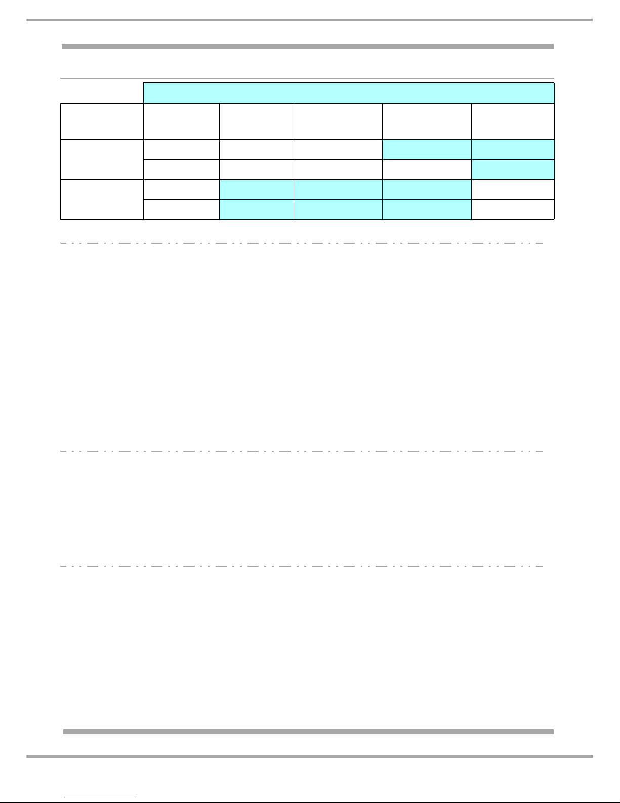
CAPACITIES / VOLUME:
Models: FF187E FF200E
Fridge Freezer Fridge Freezer
Gross 175 litre 113 litre 205 litre 113 litre
Net 173 litre 84 litre 202 litre 84 litre
Freezing Capacities 24 hrs 8 kg 8 kg
Conservation Time 12 hours 12 hours
Star Rating 4 Star **** 4 Star ****
Colour
Introduction
Date
Polar - P Graphite - G Aluminium - A Stainless Steel
(inox) - X
Black - K
Jan 2008
FF187EP FF187EG FF187EA
FF200EP FF200EG FF200EA FF200EX
May 2008
FF187EPL
FF187EK
FF200EPL
FF200EK

8 of 36
Service Manual UK
Indesit Company
English
TECHNICAL DATA:
Power Supply Voltage: 220/240 V
Power Supply Frequency: 50 Hz
Absorbed Power: 180 W
Absorbed Current: 0.5 A
COMPRESSOR WINDINGS Ω
FF187E FF200E
Manufacturer: Jiaxipera Tecumseh
Type I/D: ZBT1114CY TWB1370MJS
Winding Resistances:
Start: 16.0 Ω 26.75 Ω
R un: 13.3 Ω 15.75 Ω
Refrigerant Type / Grams: R600a - Refer to the appliance rating plate
Capacitor: Refer to Parts List
HEATER RESISTANCES
Evaporator Defrost Heater: 387.2 Ω
Gutter Heater: 1.61 KΩ
Thermal Fuse: 72 ºC
9 of 36
Indesit Company
Service Manual UK English
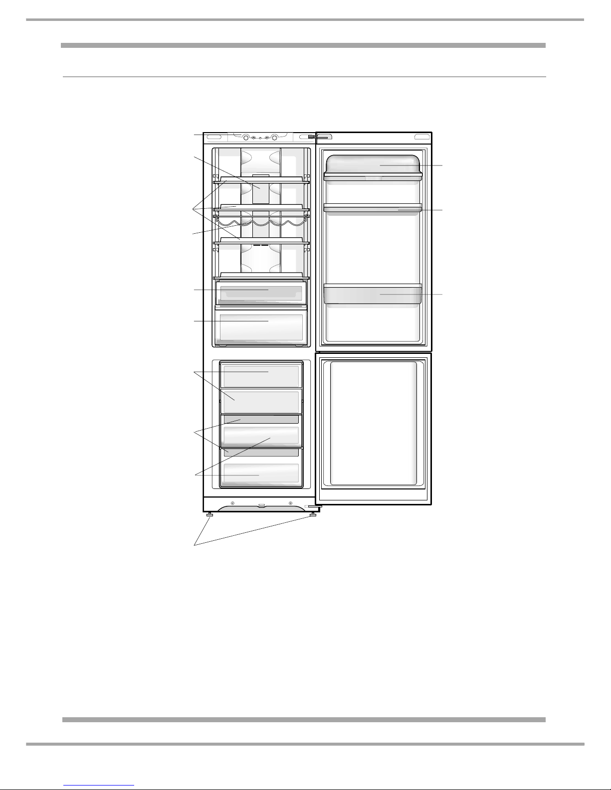
DESCRIPTION OF APPLIANCE
Detailed View
** Varies by number and/or position.
* Available only on certain models.
Removable lidded
shelf with EGG TRAY
Removable multipurpose
SHELF**
BOTTLE shelf
Control panel
FRESH BOX
Compartment
FF200E models only
FREEZER and
STORAGE compartment
STORAGE compartment
Levelling FEET
ICE CARE ice tray**
FRUIT and VEGETABE bin**
FF187E models have two half bins
LAMP
WINE RACK*
SHELVES**
10 of 36
Service Manual UK
Indesit Company
English
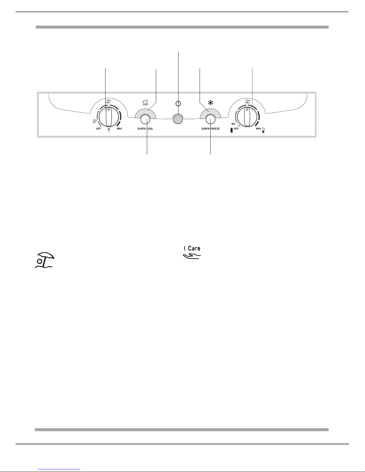
DESCRIPTION OF APPLIANCE:
NOTE: - The indicator lights are also used to indicate an unusual temperature increase in the
freezer compartment.
See Alarm Conditions on Page 12.
The SUPER COOL (quic k cool) function l owers
the temperature of the refrigerator compartment
rapidly. When the button is pressed it
illuminates the SUPER COOL indicator light.
The REFRIGERATOR OPERATION knob
allows you to adjust the refrigerator
compartment from MIN (warmer) to MAX
(colder).
The HOLIDAY function will minimise
energy usage when away on holiday.
It is not necessary to switch the
appliance off. It allows the appliance to maintain
the temperature of the refrigerator compartment
at approximately 15°C (which can be used to
conserve make-up and beauty products).
The FREEZER OPERATION knob MUST be
set to MIN in order to preserve the frozen food.
An acoustic signal sounds when this function is
enabled or disabled.
The SUPER FREEZE (fast freeze) function
allows the freezing of fresh food. When the
button is pressed it illuminates the SUPER
FREEZE indicator light.
The FREEZER OPERATION knob allows you
to adjust the freezer compartment from MIN
(warmer) to MAX (colder).
Selecting this position allows the
relevant compartment to achieve the
optimal temperature setting for energy
saving levels.
FREEZER OPERATION knob
OFF ~ Selecting this position switches the
appliance OFF including the refrigerator
compartment.
REFRIGERATOR OPERATION knob
OFF ~ Selecting this position switches the
refrigerator compartment OFF only.
SUPER FREEZE
Button
REFRIGERATOR
OPERATION
Knob
SUPER COOL
Button
SUPER COOL
Indicator light
SUPER FREEZE
Indicator light
POWER
Indicator light
FREEZER
OPERATION
Knob

11 of 36
Indesit Company
Service Manual UK English
COMPONENT FUNCTION
General Information
The power module is made up of a number of smaller individual modules (sections), each one
controlling a functional component. The modules are linked together when required to control a
particular function or function s. The linking of the indivi dual modules is optional and therefore allows for
each module to be switched ON or OFF, this is determined from the data stored or collected by the
modules and the results of module comparisons.
The power module memory stores information such as temperatures and times.
Having individual set of parameter values built in to it, directly aimed at providing the specific control
needs for the physical and system characteristics of the model type.
Fridge & Freezer Control
The power module monitors the fridge and freezer air senso rs, comparing their sensor resistance values
with the cut-in and cut-out parameter values stored in its memory.
Although the parameters are set, they allow for adjustment within those parameters so that the user has
control. The results from the comparisons will determine if cooling is initiated, other circuits of the
module will also use the results.
The power module will enable normal operation provided there is no malfunction condition.
Fridge or Freezer Malfunction Module
The fridge or freezer malfunction module enables the appliance to continue operating in the unlikely
hood of the fridge or freezer sensors failing. Pre-set timed functions stored in the module memory are
used to cycle cold request on and off.
A malfunction occurs when the fridge or freezer cabinet sensors return a value to the module of either
Open or Closed circuit, rather than a particular resistance value.
Freezer Evaporator Fan Module
The freezer fan is located above the evaporator c oil and is d esigned to di stribute the cold air pro duced
by the evaporator coil uniformly inside the freezer compartment and when necessary in the fridge
compartment.
The freezer fan is managed by the module and is switched on/off after a preset time interval that is
parameterised in the module memory after a compressor start/stop.
The defrost procedure is preceded by activation of the fan for a timed interval that is parameterised in
the module memory. The fan will not operate when in the defrost cycle.
After the defrost cycle the fan starts after a timed interval following a compressor start, this interval is
also parameterised in the module memory; this interval is different from the interval programmed for
normal operating conditions.
Electronic Motorised Damper Assembly (Baffle)
The purpose of the damper is to a llow the c old air pr oduced by the free zer evapo rator to be distributed
inside the refrigerator compartment.
The damper is located behind the fridge multi-flow unit in the upper section. It is controlled by a
thermistor positioned into the exhaust (return) duct connecting the evaporator to the damper.
Cold air from the evaporator is distributed in the refrigerator compartment by open ings on the multi-flow
unit. (See the Air Flow Diagram on page 18.)
 Loading...