

Hotpoint FDYF11011K, FDYF11011G, FDYF11011P Service Information
Indesit Company UK Ltd
© 2015 Reg. Office: Peterborough PE2 9JB Registered in London: 106725
Service
Information
Hotpoint
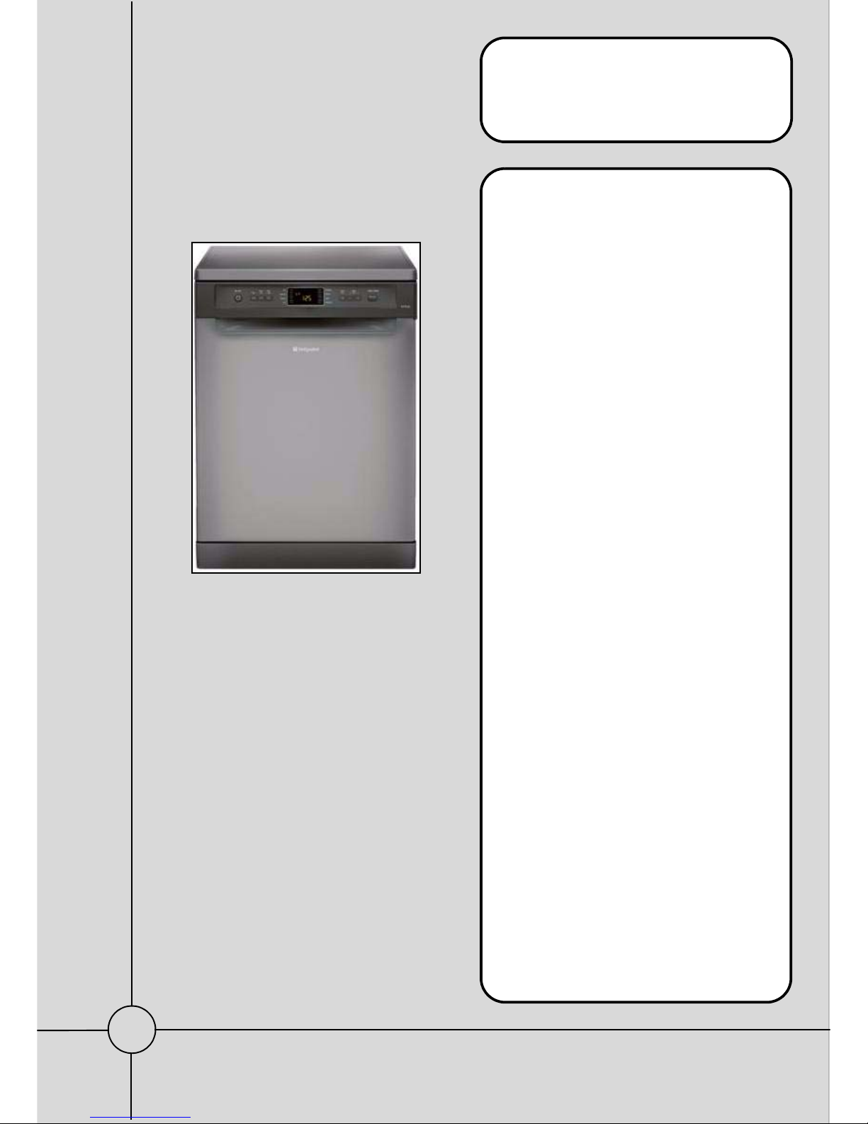
Freestanding
DISHWASHER
with
Digit Display
using
DEA700 & DEA603
controls
Models Covered:
Comm
Model: Code
FDYF11011G 82748
FDYF11011K 82752
FDYF11011P 82746
5407865 Issue 1 Feb. 2015.
SM004058 ~ C00309783

2 of 39
Service Manual UK
Indesit Company
English
SAFETY NOTES & GENERAL SERVICING ADVICE
1. This manual is NOT intended as a comprehensive repair/maintenance guide to the appliance.
2. It should ONLY be used by suitably qualified persons having technical competence applicable product
knowledge and suitable tools and test equipment.
3. Servicing of electrical appliances must be undertaken with the appliance disconnected (unplugged) from
the electrical supply.
4. Servicing must be preceded by Earth Continuity and Insulation Resistance checks.
5. Personal safety precautions must be taken to protect against accidents caused by sharp edges on metal
and plastic parts.
6. After Servicing the appliance must be rechecked for Electrical Safety. In the case of appliances which
are connected to a water supply (i.e.: Washing Machines, Dishwashers & Food Centres etc.) checks
must be made for leaks from seals gaskets and pipe work and rectification carried out where necessary.
7. It can be dangerous to attempt ‘DIY’ repairs / maintenance on complex equipment and the Company
recommends that any problem with the appliance is referred to its own Service Organisation.
8. Whilst the Company has endeavoured to ensure the accuracy of the data within this publication they
cannot hold themselves responsible for any inconvenience or loss occasioned by any error within.
INDEX
Safety Notes & General Servicing Advice . . . . . . . . . . . . . . . . . . . . . . . . . . . . . . . . . . . . . . . . 2
Product Fiche . . . . . . . . . . . . . . . . . . . . . . . . . . . . . . . . . . . . . . . . . . . . . . . . . . . . . . . . . . . . . . . 3
Technical Specifications . . . . . . . . . . . . . . . . . . . . . . . . . . . . . . . . . . . . . . . . . . . . . . . . . . . . . . 4
Fault Codes & Diagnostics . . . . . . . . . . . . . . . . . . . . . . . . . . . . . . . . . . . . . . . . . . . . . . . . . .5 - 8
Wiring Diagram / Power Module photo. . . . . . . . . . . . . . . . . . . . . . . . . . . . . . . . . . . . . . . .9 - 10
General Information . . . . . . . . . . . . . . . . . . . . . . . . . . . . . . . . . . . . . . . . . . . . . . . . . . . . . . . . . 11
Console Panel. . . . . . . . . . . . . . . . . . . . . . . . . . . . . . . . . . . . . . . . . . . . . . . . . . . . . . . . . . .12 - 14
Basic Use and Setup . . . . . . . . . . . . . . . . . . . . . . . . . . . . . . . . . . . . . . . . . . . . . . . . . . . . . . . . 15
Programme Guide . . . . . . . . . . . . . . . . . . . . . . . . . . . . . . . . . . . . . . . . . . . . . . . . . . . . . . . . . . 16
Component Description. . . . . . . . . . . . . . . . . . . . . . . . . . . . . . . . . . . . . . . . . . . . . . . . . . .17 - 21
Auto Test Cycle . . . . . . . . . . . . . . . . . . . . . . . . . . . . . . . . . . . . . . . . . . . . . . . . . . . . . . . . .22 - 23
Dismantling Instructions . . . . . . . . . . . . . . . . . . . . . . . . . . . . . . . . . . . . . . . . . . . . . . . . . .24 - 30
Module Programming. . . . . . . . . . . . . . . . . . . . . . . . . . . . . . . . . . . . . . . . . . . . . . . . . . . . .31 - 32
General Dishwashing Information . . . . . . . . . . . . . . . . . . . . . . . . . . . . . . . . . . . . . . . . . .33 - 36
Production Changes
First production models were fitted with DEA700 electronics
The DEA603 electronics module replaced DEA700 in production with the introduction of
Industrial code ending xxxxxxx 2500.
3 of 39
Indesit Company
Service Manual UK English
Model Matrix - FDYF11011P
Product Fiche - FDYF11011
FD Y F 1 1 01 1 P
Build Product Size Interface Basket
Water
Load
Motor
Type
Energy
Cutlery
Tray
Colour
F=Free-
standing
D=Dish-
washer
E=Experi-
ence
Y=Style
F=Futura
A=Aquarius
U=Ultima
F=Digit
B=Basic
Led
L= Led+
D=LCD
3=Flexiload
med.
1=Flexiload
Basic
4=Flexiload
High
5=Flexiload
Star
3=9 litres
1=12 Litres
2=10 Litres
4=7 Litres
0=Sync
Motor
1= Flex-
ipower
2=A++
1=A+
3=A+++
0=Stand-
ard
1=Cutlery
Tray
2=N/A
3=Active
O2
P=Polar
G=Graph-
ite
K=Black
V=Cream
SB=Gun
metal
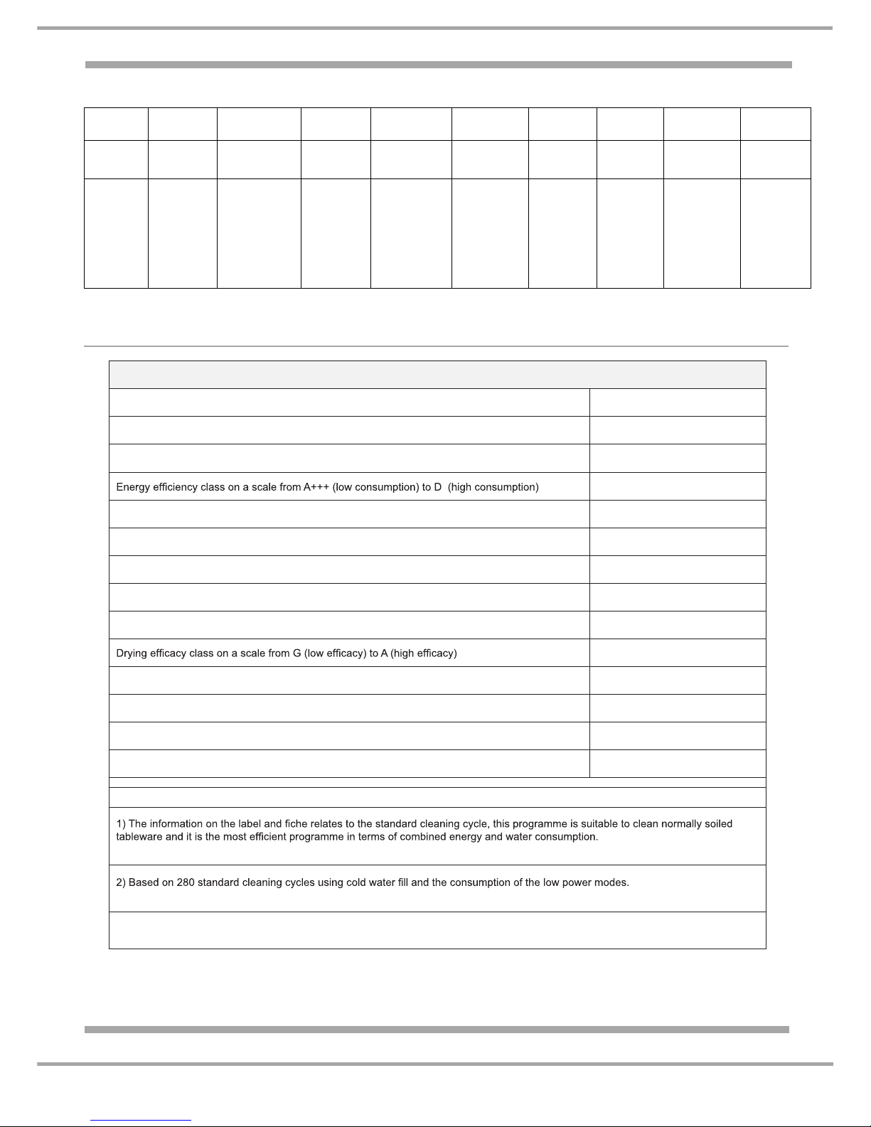
Product Fiche
Brand
HOTPOINT
Model
FDYF 11011
Rated capacity in standard place settings (1)
13
A+
Energy consumption per year in kWh (2)
295.0
Energy consumption of the standard cleaning cycle in kWh
1.04
Power consumption of the off-mode in W
0.5
Power consumption of the left-on mode in W
5.0
Water consumption per year in litres (3)
3080.0
A
Programme time for standard cleaning cycle in minutes
190’
The duration of the left-on mode in minutes
10
Noise in dB(A) Re 1pW
49
Built-in model
No
NOTES
The standard cleaning cycle
corresponds to the Eco cycle.
Actual energy
consumption depends on how the appliance is used.
3) Based on 280 standard cleaning cycles. Actual water consumption depends on how the appliance is used.

4 of 39
Service Manual UK
Indesit Company
English
TECHNICAL SPECIFICATIONS
Models FDYF11011G 82748 Graphite
FDYF11011K 82752 Black
FDYF11011P 82746 White
First Production 2013
Energy Class A+
Washing Class A
Drying Class A
Noise Level 49 dB
Country of Origin Poland
Dimensions Height - 850 mm
Width - 600 mm
Depth - 600mm
Capacity 13 place settings
Electrical Supply 220/240 Volts AC @ 50Hz
Cable Length: 1.28 Metres
Energy Consumption Off Mode: 0.5 Watts
(2011 Regulations) Left On Mode: 5 Watts
Standard Cycle: 1.04 kW/h
Water Consumption Standard Cycle: 11 litres
Drying Natural Drying
Controls Electronic DEA 700 or DEA603 (Industrial Code ending ’2500’ )
Tub Stainless Steel
Heater type Flow through type with built in safety cut out and fuse
Heater Wattage 1.8 kW @ 230V AC
Heater Resistance 29.20Ω
Circulation Motor Synchronous
Detergent Dispenser Capacity 25g + 5g ** only available as part of the door panel
Rinse Aid Dispenser Capacity 140ml
Fill Valve Resistance 3.72 KΩ approx.
Water Pressure 0.56 bar (Max 10 bar)
Regeneration Valve 4.1 KΩ approx.
Drain Pump Synchronous motor
Power Consumption: 26 Watts
Thermistor Sump Mounted
Wash Programmes 8 - Eco, Auto Intensive, Auto Normal, Auto Fast, Duo Wash,
Delicates, Express 30’, Soak.
Wash Temperatures Between 50
°C and 70°C
Salt Refill Indicator Symbol on display
Rinse Aid Indicator Symbol on display
Supply Water Pressure 0.5 to 10 Bar (7.25 psi - 145 psi)
5 of 39
Indesit Company
Service Manual UK English
FAULT CODES - Basic
If there is a fault (active):
The service technician will find the machine immobilized, with the Fault Code shown in the display and
other LEDs on the Control Panel blinking (usually On/Off, Salt and Rinse Aid).
Refer to the Fault Code chart below for guidance.
If Warning or Last Fault is indicated:
Starting the autotest, the last Fault or the current Warning will be displayed for 20 seconds.
Once this time has elapsed, the autotest sequence starts automatically.
If the autotest reaches the end, the Last Fault will be reset.
Should the Autotest procedure be interrupted for whatever reason, data in the Last Fault memory will be
saved. N.B.: The "Last Fault detected electronically" will always be displayed.
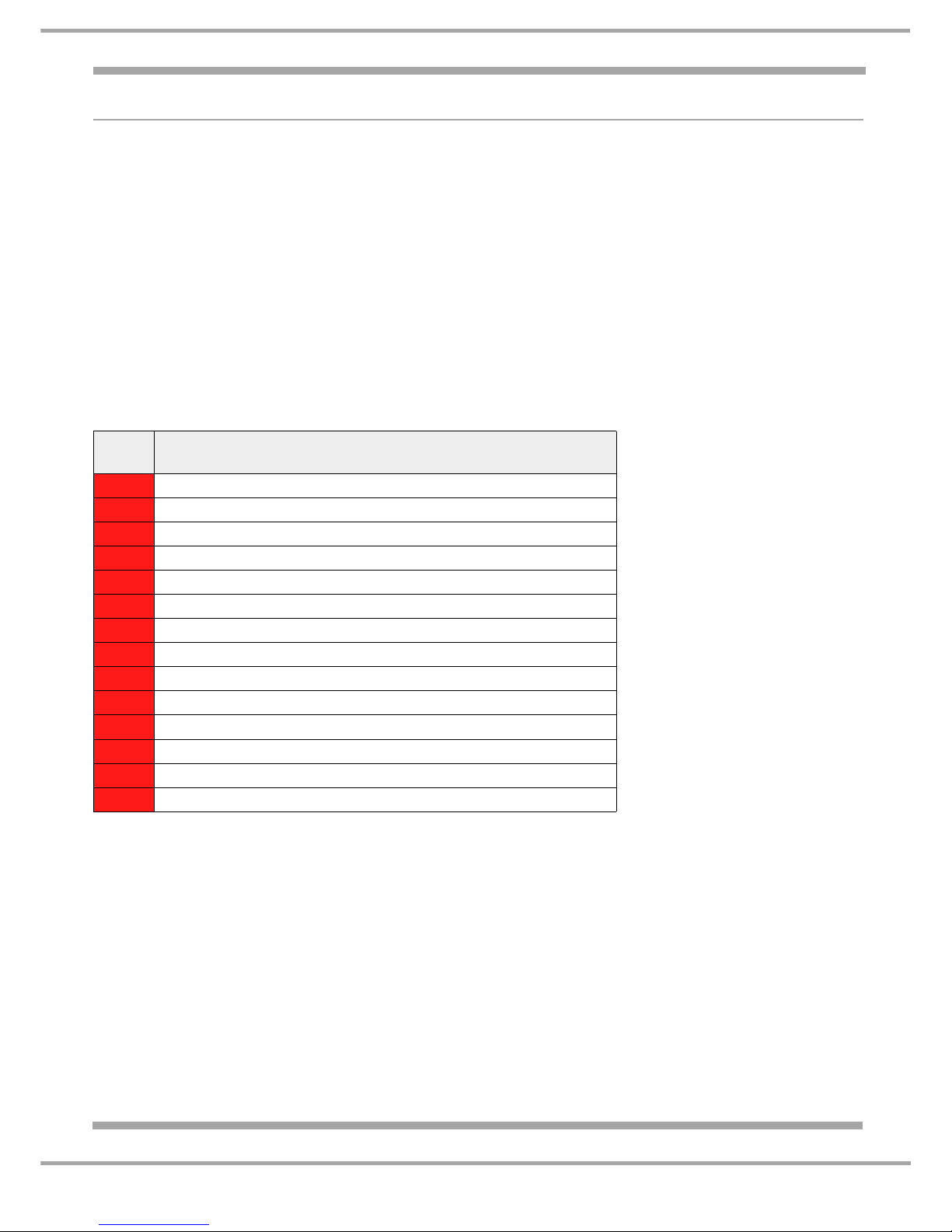
Basic Fault Code Chart
For more detailed information refer to next page.
Fault Possible Cause
F01
ANTI-FLOODING OVERFLOW
F02
WATER FILL SOLENOID VALVE FAILURE
F03
DRAIN TIMEOUT
F04
THERMISTOR (NTC) not compliant
F05
Not applicable to this model
F06
WATER FILL TIMEOUT
F07
WATER TURBINE damaged
F08
TEMPERATURE TIMEOUT (1 hour)
F09
Software recognition error.
F10
HEATING ELEMENT CIRCUIT not compliant
F11
Not applicable to this model
F12
COMMUNICATION error between main board and display
F13
MAIN BOARD not Working
F15
VIRTUAL SENSOR - Inconsistent readings
6 of 39
Service Manual UK
Indesit Company
English
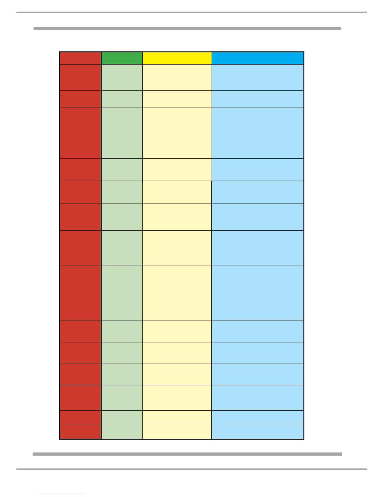
FAULT CODES - Detailed
- Pressure switch faulty;
- Pressure switch tube damaged;
- Water in air trap;
- Air trap damaged.
- Tap closed or partially closed;
- Filler hose pinched;
- Filler hose ſlter clogged/bent;
- Water pressure low or ƀow meter doesn’t work;
- Water solenoid valve faulty or disconnected.
- Turbine faulty or disconnected;
- Connector terminals not making contact;
- Turbine wiring faulty;
- Turbine faulty, disconnected or wet;
- WATER has been introduced manually;
- Filler hose ſlter obstructed;
- Pressure switch faulty.
- NTC sensor bracket detached from bowl;
- Fault in electrical circuit of heating element;
- Heating element ITR incorrectly calibrated/faulty;
- Excessive suds;
- Heating element false contact
- NTC sensor incorrectly calibrated
- Lime scale on heating element.Water hardness
setting not compliant. User not putting in salt
- NTC sensor separated from socket (replaces
ſrst check)
- Heating element defective.
- Main board not programmed;
- Incorrect setting ſle.
- Heating element cables disconnected;
- Main board relay defective
- Heating element defective;
- Main board relay defective.
- Fault in Main board/user interface wiring;
- Disconnect from electrical power supply.Wait 2
minutes.Reconnect appliance to power supply
and test again;
- User interface defective.
- Replace main board.
- Replace wash pump.
Pressure switch has not indicated
completion of fill, even though
turbine has filled appliance with
water correctly.
Maximum interval of time for completion of ſll has been exceeded.
Turbine has given no signal indicating entry of water, even though ſll
has effectively been completed.
Maximum interval of time for establishing temperature has been
exceeded (1 hour).
Software recognition error Processor not programmed.
HEATING ELEMENT CIRCUIT not
Note:
This code may display
during an Auto Test
If the dishwasher is working normally,
ignore this Fault Code during an Auto Test.
compliant (circuit open).
No communication/connection
between main board and user
interface.
Main board NOT WORKING
Reading between Wash pump and
Drain pump not consistent.
PRESSURE SWITCH
non compliant
WATER FILL
TIMEOUT
WATER TURBINE
damaged
TEMPERATURE
TIMEOUT (1 hour)
Software recogni-
tion error. Main
board not pro-
grammed
HEATING ELE-
MENT CIRCUIT not
compliant
Not Applicable
to this model
COMMUNICATION
error between main
board and display
Main board NOT
WORKING
VIRTUAL SENSOR
F05
F06
F07
F08
F09
F10
F11
F12
F13
F15
- Water leak;
- Float switch or wiring defective;
- New main board: Eeprom was programmed
off-site; to reset thealarm, switch off and switch
on again using the ON/OFF button.
- Fill solenoid valve failure;
- Main boardſll solenoid valve triacshort-circuiting;
- Make certain drain hose is not on the ƀoor.
- Drain pump blocked by foreign matter;
- Drain pump faulty/disconnected;
- Drain hose blocked;
- Drain trap blocked;
- Air bubble in hose;
- Check drain pump wiring and connectors at
component end and main board end;
- Check integrity of drain pump impeller;
- Replace drain pump.
- NTC sensor cables disconnected or damaged;
- Cablesor connectors disconnectedor short-circuiting;
- NTC sensor wet, short-circuit;
- NTC sensor damaged, open circuit.
Bowl ƀoat microswitch electrical
circuit OPEN! (must be closed)
Fill valve admits water even when
deactivated.
Maximum drain time elapsed.
THERMISTOR (NTC) circuit not
compliant (break in continuity or
short-circuit)
FAULT
CODE
F01
ANTI-FLOODING
OVERFLOW
WATER FILL
SOLENOID VALVE
FAILURE
DRAIN TIMEOUT
THERMISTOR (NTC)
not compliant
NAME
POSSIBLE CAUSE
CHECKS
F02
F03
F04
7 of 39
Indesit Company
Service Manual UK English
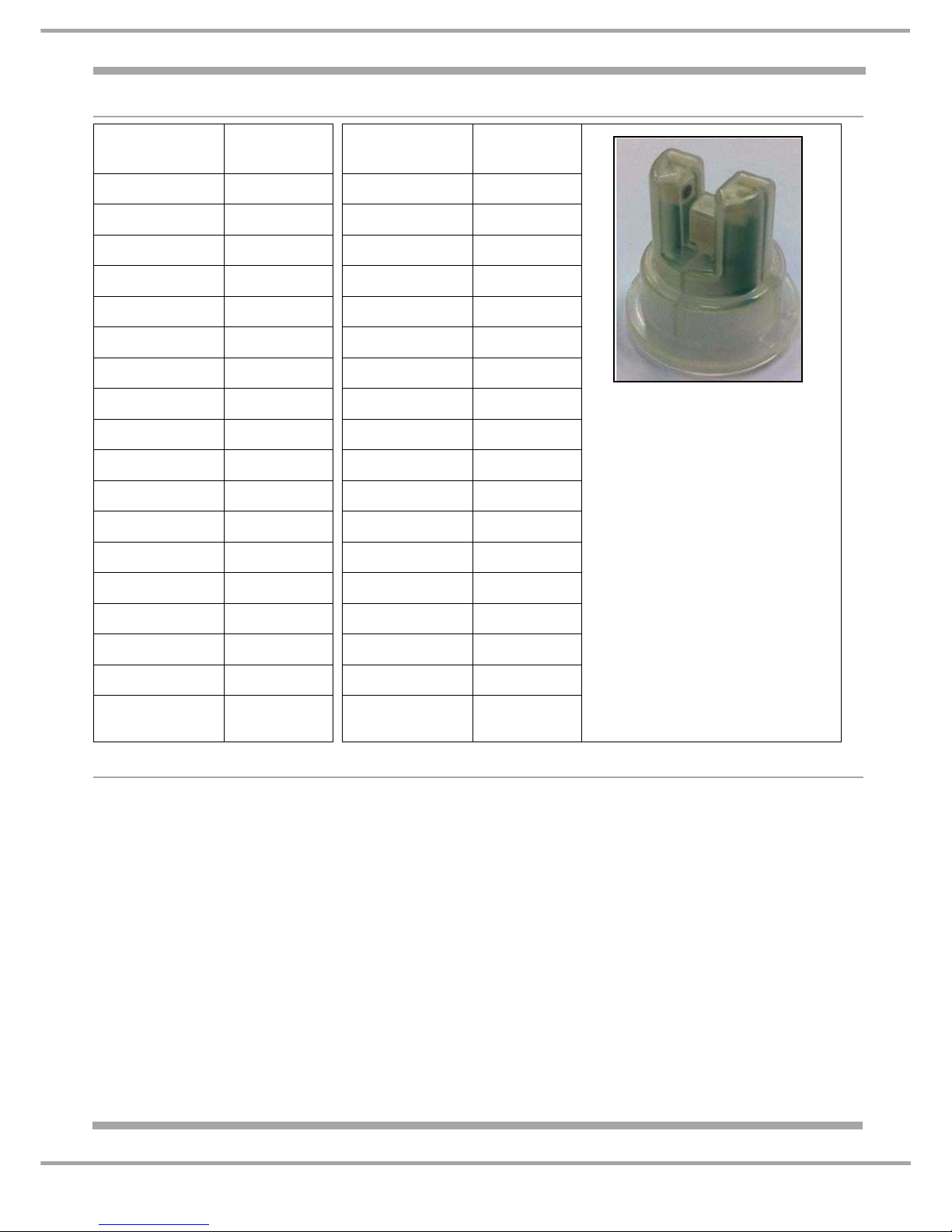
Thermistor - Resistance Chart
Fault Notes
• Filling
After the initial drain period, it is norma l at the start of a cycle for the machine to pause for a perio d
before filling.
• Heating Element
An open circuit heating element can display either the heating time out fault code or the open
circuit heater fault code (F8 & F10), depending on the cycle in progress or the phase of the cycle
when the heater fails.
If a dishwasher has an open circuit heating element, the machine may run for up to 75 minutes
before a fault code will display.
It is recommended before a module is replaced or when the fault is not obvious, the heating
element is tested for continuity and resistance to Earth at its terminals, with the heater
disconnected.
continued...
Temperature
in degrees C
Resistance
in K Ohms
Temperature
in degrees C
Resistance
in K Ohms
- 40 24751.661 50 146.215
- 35 17127.169 55 117.828
- 30 12014.762 60 95.420
- 25 8524.305 65 77.718
- 20 6113.811 70 63.584
- 15 4435.437 75 52.260
- 10 3249.216 80 43.166
- 5 2403.515 85 35.808
0 1794.358 90 29.828
+ 5 1351.294 95 24.961
10 1025.870 100 20.955
15 785.018 105 17.668
20 605.252 110 14.951
25 470.000 115 12.695
30 367.480 120 10.824
35 289.186 125 9.259
40 229.014
45 182.485

8 of 39
Service Manual UK
Indesit Company
English
• Programme Times
The times in the handbook and displayed at the start of the cycle, are average times and will be
affected by the following points:
• Inlet water temperature below 19°C
• Tab option enabled
• Water hardness setting set to positions 4 or 5
• Condition of the heating element (limescale built up)
• Excessive foam caused by using tablets with a small or light load.
NOTE: - The display is not a coun t down timer. It is normal occasionally for the same time to show
for an extended period.
• Machine Starts up for a few minutes when not in use
The machine inlet valve is 'letting by' and water is leaking into the machine when not in use.
Providing the machine is plugged in and the door close d (it does not have to be switched on), once
the water in the machine is enough to operate the pressure switch to full level, the machine drain
pump will energise until the pressure switch resets to empty (plus 30 seconds).
Note: - Fault code F2 displays if the water letting by is fast enough to be recognised by the water
turbine.
Indesit Company
9 of 39
Service Manual UK English
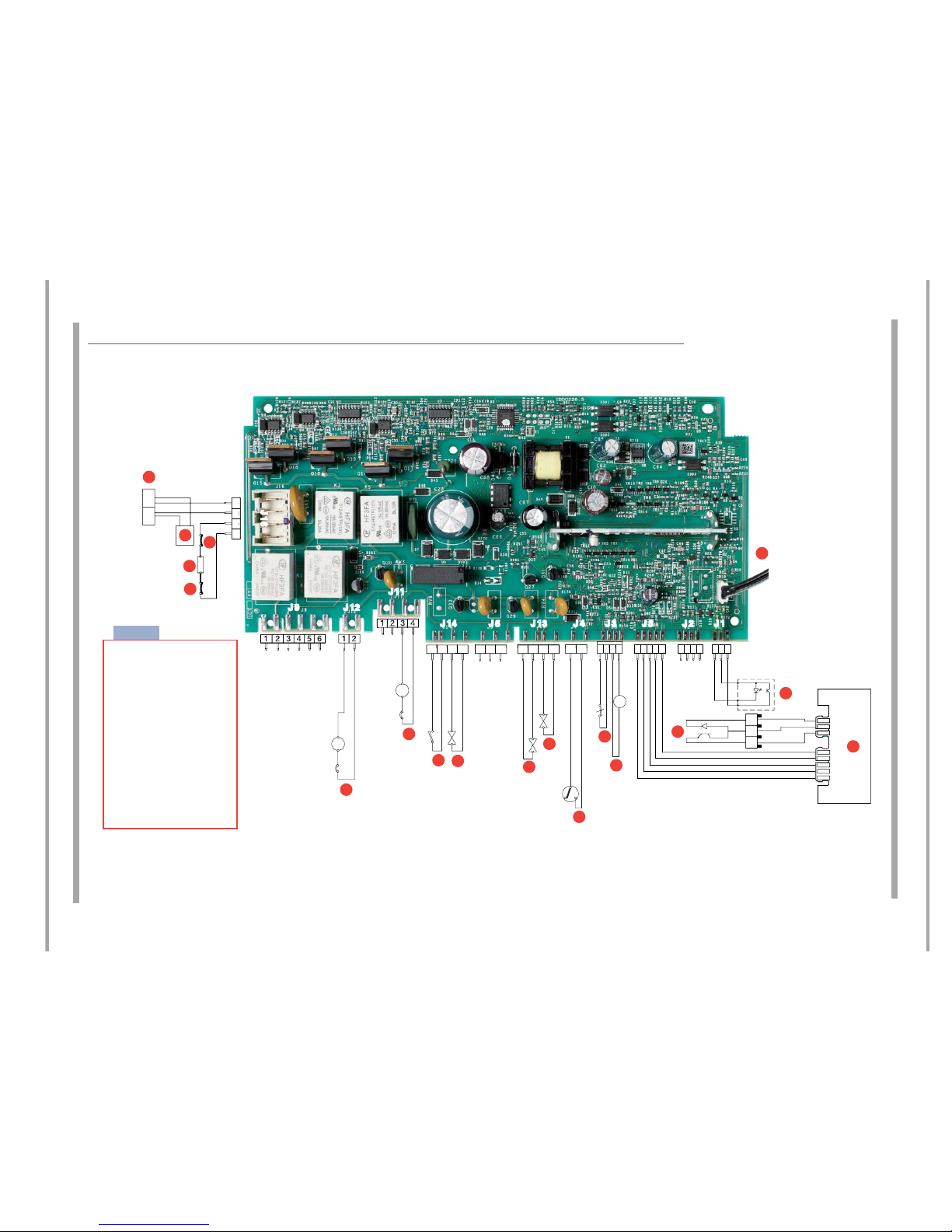
WIRING DIAGRAM DEA700 Module
1234
65432121
4321
54321
12
3
J 9
J 11
J 12
J 5 J 13 J 8J 14 J 4 J2J 3 J 1
J
16
P
N
O
M
S
C
A
H
G
L
I
R
Q
Key:
D
E
NL
B
F
A Mains power
B Noise lter
C Heating element
D Thermoprotector (95°C)
E Thermal fuse (206°C)
F Synchronous drain pump
G Synchronous washing motor
H Door microswitch
I Dispenser solenoid valve
L Load solenoid valve
M Regeneration solenoid valve
N Pressure switch
O Overow switch
P Meter turbine
Q Rinse aid reader
R User interface
S Salt reader
T Temperature sensor
T
4321
432121
4321
321
54321 321 32
1
DEA700
Module
Indesit Company
10 of 39
Service Manual UK English
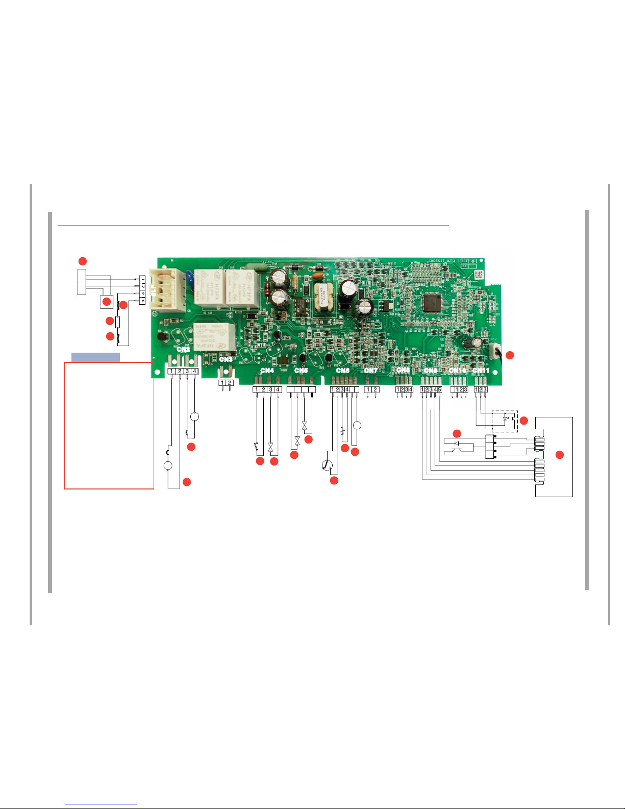
WIRING DIAGRAM DEA603 Module
1234
4321
21
4321 543213 4 2121 3214321 32
1
54
3
2
112
3
4321 5 6
P
N
O
M
CN2
S
CN3
CN5 CN9
CN4
CN7 CN10 CN11
J 16
C
A
H
G
L
I
R
Q
D
E
NL
B
F
CN6
CN8
Key:
A Mains power
B Noise lter
C Heating element
D Thermoprotector (95°C)
E Thermal fuse (206°C)
F Synchronous drain pump
G Synchronous washing motor
H Door microswitch
I Dispenser solenoid valve
L Load solenoid valve
M Regeneration solenoid valve
N Pressure switch
O Overow switch
P Meter turbine
Q Rinse aid reader
R User interface
S Salt reader
T Temperature sensor
T
DEA603
Module
11 of 39
Indesit Company
Service Manual UK English
GENERAL INFORMATION
These models are freestanding front loading Dishwashers providing a choice of 8 Wash Cycles.
They have A+ Energy performance.
Programmes and all Options are set using the display, which is mounted on the console.
Extra Dry, Tabs, Half Load, Shortime and Delay Options are also available on selected programmes.
Smaller loads can be washed using either the top or bottom ba sket.
There are "Low" warning indicators on the console display for Salt and Rinse Aid.
The user adjusts Water Hardness before the machine is first used.
Rinse Aid is electronically controlled and has to be adjusted from the Console.
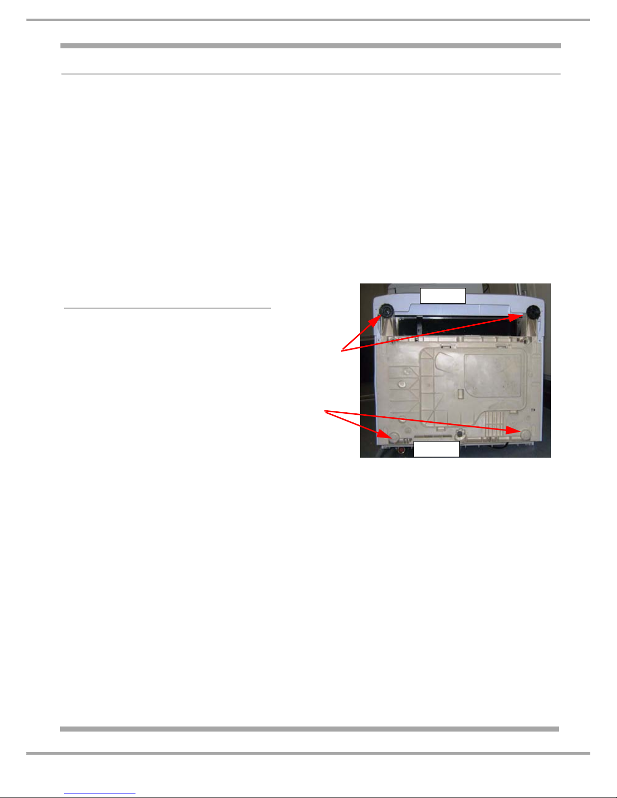
Levelling the Dishwasher
There are 2 adjustable feet at the front.
There are 2 solid moulded sliders at the
rear.
The dishwasher must be level to prevent
distortion of the cabinet and poor closing of
the door.
Refer to the photo (right) of the dishwasher
seen from underneath.
Adjustable
Non-adjustable
sliders
Front
Rear
Feet
12 of 39
Service Manual UK
Indesit Company
English
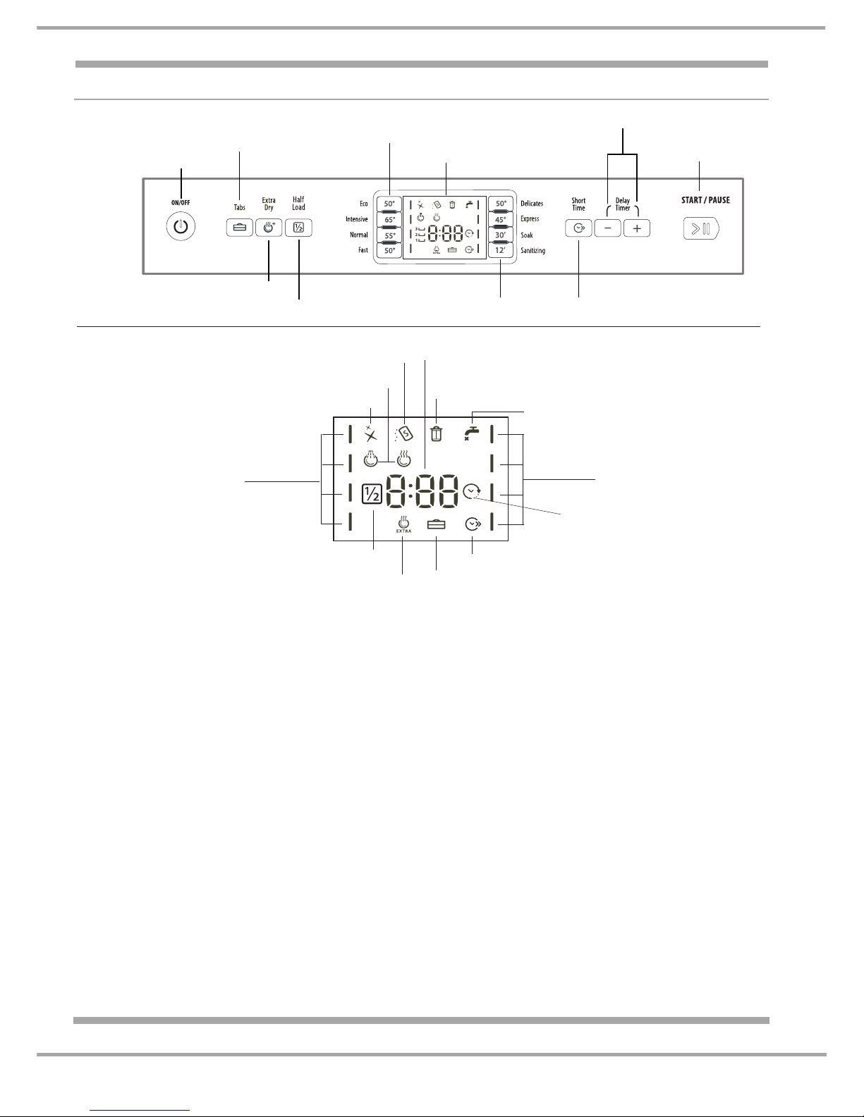
CONSOLE P ANEL
The following information is displayed during a cycle.
> Estimated Programme duration time
This will countdown as the cycle progresses, and the time to finish will automatically update as the
programme progresses.
The first programme displayed will always be the most commonly used programme.
This is not a countdown timer, but an estimate time to the end of the cycle.
> If an Option as been selected a bar will illuminate above the Option button.
Fault Codes will display in the event of a machine failure - for example: F 6
Other information messages will scroll across the Display.
ON-OFF/RESET BUTTON
Press this button to switch the appliance on.
To Re-set a programme that requires cancelling press and hold down the On-Off button.
ON-OFF INDICATOR LAMP
This Lamp shows that the Dishwasher is Switched on.
Display
Wash cycle
Wash cycle
Half Load indicator light
Low Rinse Aid indicator light
Low Salt indicator light
Blocked Filter indicator light
Extra Drying indicator light Multi-Functional Tablets indicator light (Tabs)
Washing and Drying indicator lights
Tap Shut-Off indicator light
Delayed Start
indicator light
Remaining Time indicator
Short Time option indicator light
Control Panel
Start/Pause button
and indicator lights
On-Off/Reset button
and indicator light
Extra Drying option button
Half Load option button
Delayed Start buttons
Multi-functional Tablets
option button (Tabs)
Display
Wash-Cycle Selection buttons
Short Time option button
Wash-Cycle Selection buttons
*** Only in completely built-in models * Only available in selected models.
The number and type of wash cycles and options may vary depending on the dishwasher model.
 Loading...