

Page 1
Indesit Company UK Ltd
© 2010 Reg. Office: Peterborough PE2 9JB Registered in London: 106725
Service
Information
Hotpoint
Freestanding
DISHWASHER
Model Covered
Hotpoint
Italian manufacture
FDM550P 54445
FDM554P 63569
Polish manufacture
FDM550P.R 56396
FDM554P.R 64674
5407485 Issue 3 June 2010
Page 2

2 of 35
Service Manual UK
Indesit Company
English
SAFETY NOTES & GENERAL SERVICING ADVICE
1. This manual is NOT intended as a comprehensive repair/maintenance guide to the appliance.
2. It should ONLY be used by suitably qualified persons having technical competence applicable
product knowledge and suitable tools and test equipment.
3. Servicing of electrical appliances must be undertaken with the appliance disconnected (unplugged)
from the electrical supply.
4. Servicing must be preceded by Earth Continuity and Insulation Resistance checks.
5. Personal safety precautions must be taken to protect against accidents caused by sharp edges on
metal and plastic parts.
6. After Servicing the appliance must be rechecked for Electrical Safety. In the case of appliances which
are connected to a water supply (i.e.: Washing Machines, Dishwashers & Food Centres etc.) checks
must be made for leaks from seals gaskets and pipe work and rectification carried out where
necessary.
7. It can be dangerous to attempt ‘DIY’ repairs / maintenance on complex equipment and the Company
recommends that any problem with the appliance is referred to its own Service Organisation.
8. Whilst the Company has endeavoured to ensure the accuracy of the data within this publication they
cannot hold themselves responsible for any inconvenience or loss occasioned by any error within.
INDEX
Safety Notes & General Servicing Advice . . . . . . . . . . . . . . . . . . . . . . . . . . . . . . . . . . . . . . 2
Technical Specifications . . . . . . . . . . . . . . . . . . . . . . . . . . . . . . . . . . . . . . . . . . . . . . . . . . . .3
General Information . . . . . . . . . . . . . . . . . . . . . . . . . . . . . . . . . . . . . . . . . . . . . . . . . . . . . . . . 4
Console Panel. . . . . . . . . . . . . . . . . . . . . . . . . . . . . . . . . . . . . . . . . . . . . . . . . . . . . . . . . . . . . 5
Programme Guide . . . . . . . . . . . . . . . . . . . . . . . . . . . . . . . . . . . . . . . . . . . . . . . . . . . . . . 6 - 7
Setting the Water Hardness. . . . . . . . . . . . . . . . . . . . . . . . . . . . . . . . . . . . . . . . . . . . . . . . . . 8
Component Description. . . . . . . . . . . . . . . . . . . . . . . . . . . . . . . . . . . . . . . . . . . . . . . . . 9 - 13
Fault Codes & Diagnostics . . . . . . . . . . . . . . . . . . . . . . . . . . . . . . . . . . . . . . . . . . . . . 14 - 19
Wiring Diagram - models fitted with DEA601 Power Module . . . . . . . . . . . . . . . . . . . . . . 20
Wiring Diagram - models fitted with DEA602 Power Module . . . . . . . . . . . . . . . . . . . . . . 21
Power Module photo . . . . . . . . . . . . . . . . . . . . . . . . . . . . . . . . . . . . . . . . . . . . . . . . . . . . . .22
Module Programming. . . . . . . . . . . . . . . . . . . . . . . . . . . . . . . . . . . . . . . . . . . . . . . . . . 23 - 24
Dismantling Instructions . . . . . . . . . . . . . . . . . . . . . . . . . . . . . . . . . . . . . . . . . . . . . . . 25 - 30
General Dishwashing Information . . . . . . . . . . . . . . . . . . . . . . . . . . . . . . . . . . . . . . . 31 - 34
Production Changes
DEA602 Power Module Introduced:
FDM550P.R - from Serial Number 91231.9999
FDM554P.R - from Serial Number 91023.9999
Standby Function Added:
All Models from March 2010
Page 3

3 of 35
Indesit Company
Service Manual UK English
TECHNICAL SPECIFICATIONS
Models FDM550P - 54445 - White
FDM554P - 63569 - White
FDM550P.R - 56396 - White
FDM554P.R - 64674 - White
Energy Class A
Washing Class A
Drying Class A
Noise Level 51dB
Country of Origin FDM550P - FDM5504P:- Italy
FDM550P.R - FDM554P.R:- Poland
Dimensions Height 850 mm
Width 595 mm
Depth 570 mm
Weight 43 Kg
Capacity 12 place settings - FDM550P + FDM550P.R
14 place settings - FDM554P + FDM5540.R
Electrical Supply 230/240 Volts AC @ 50Hz
Energy Consumption Standard Cycle: 1.08kW/h
Water Consumption Standard Cycle: 15 litres
Drying Residual Heat Drying (Natural)
Controls Electronic DEA 601 with soldered EEPROM - see Production changes
or Electronic DEA 602 with soldered EEPROM - see Production changes
Tub Stainless Steel
Heater type Flow through type with built in safety cut out and fuse
Heater Wattage 1.8 kW @ 230V AC
Heater Resistance 29.20Ω
Circulation Motor Synchronous Motor
Motor RPM 2800
Motor Power Consumption 60 Watts
Detergent Dispenser Capacity 25g + 5g
Rinse Aid Dispenser Capacity 14 0ml
Fill Valve Resistance 3.72KΩ approx.
Water Pressure 0.56 bar (Max 10 bar)
Regeneration Valve 4.1KΩ approx.
Drain Pump Plaset Motor Synchronous
Motor Winding Resistance: 216Ω + or - 7%
Power Consumption: 26 Watts
Thermistor Sump Mounted
Wash Programmes 5 - Intensive, Normal, Prewash, Eco, Fast Wash
Wash Temperatures 45°C, 52°C, 48°C, 63°C
Salt Refill Indicator LED on console
Rinse Aid Indicator LED on console
Page 4
4 of 35
Service Manual UK
Indesit Company
English
GENERAL INFORMATION
This model is a freestanding front loading dishwasher providing a choice of 5 wash programmes to
suit load requirements.
The Programme Selector, Option buttons and LED indicators are mounted on the front panel.
There are "Low" warning LED’s mounted on the Console for Salt and Rinse Aid.
Water hardness is adjusted by the user before the machine is first used.
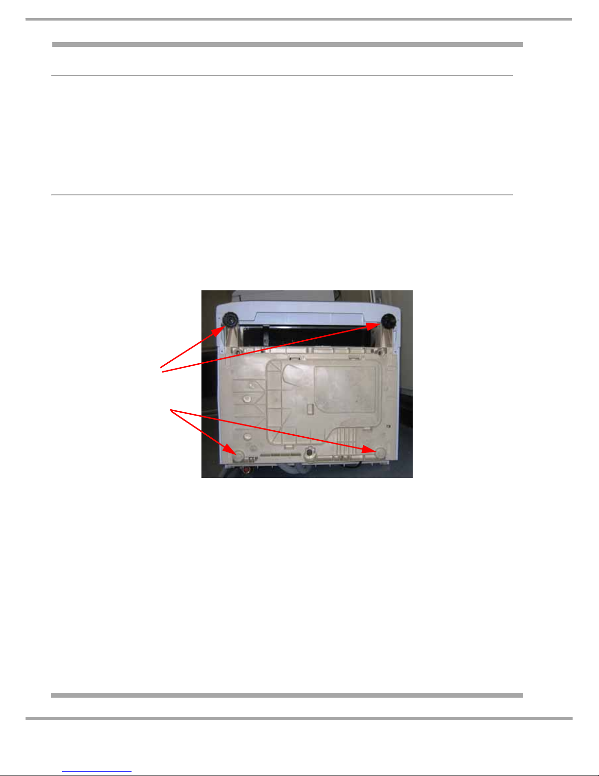
Levelling the Dishwasher
There are 2 adjustable feet at the front.
There are 2 solid moulded sliders at the rear.
The dishwasher must be level to prevent distortion of the cabinet and poor closing of the door.
Dishwasher seen from underneath.
Adjustable Feet
Non-adjustable
sliders
Front
Rear
Page 5
5 of 35
Indesit Company
Service Manual UK English
CONSOLE PANEL
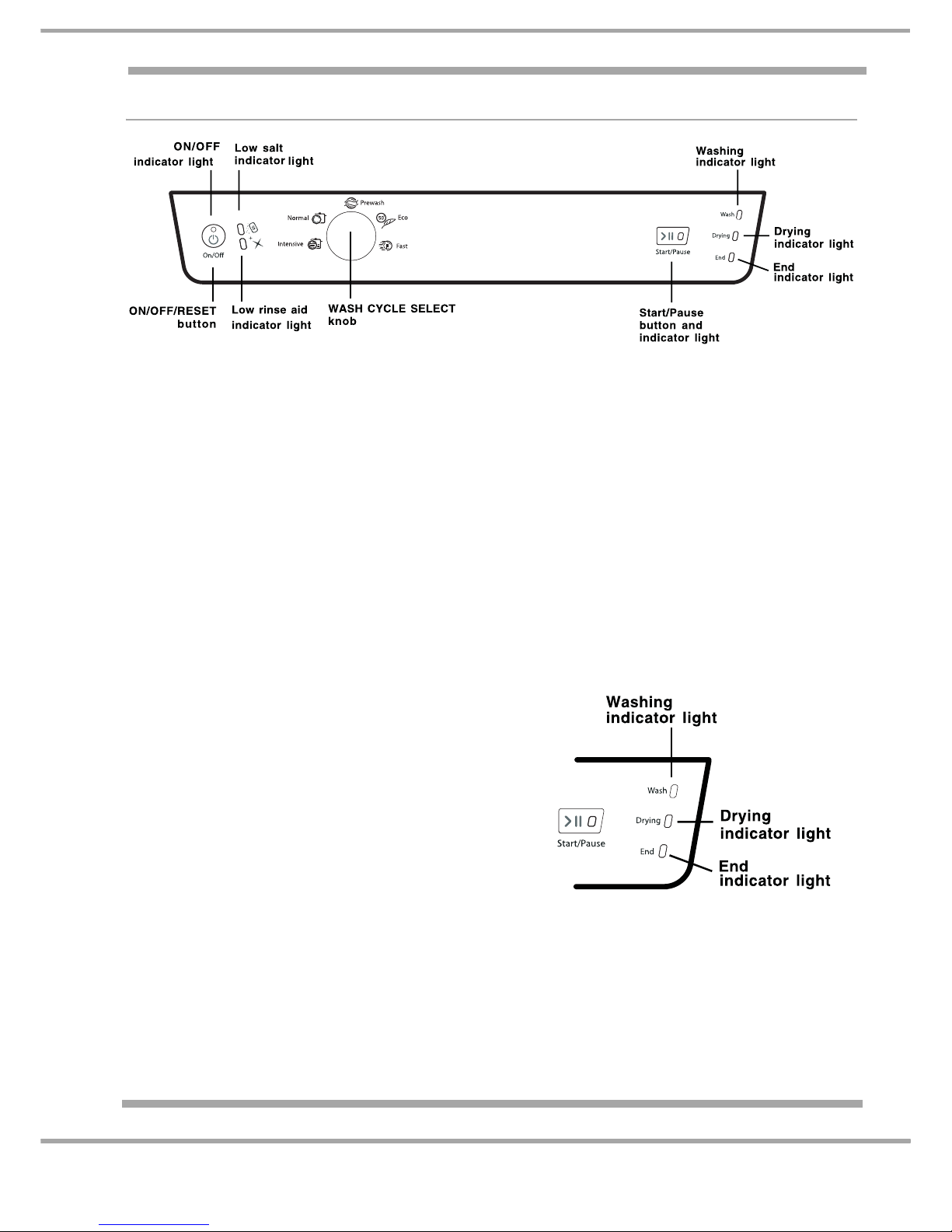
ON-OFF/RESET BUTTON
Press this button to switch the appliance on.
To Re-set a programme that requires cancelling press and hold down the On-Off button.
ON-OFF INDICATOR LAMP
This Lamp shows that the Dishwasher is Switched on.
START/PAUSE BUTTON
Once the Programme and Options required have been selected. Pushing this button once will
start the selected Programme.
During a Programme if this button is pushed the Cycle will stop until the button is pushed
again, when the cycle will continue.
START/PAUSE INDICATOR LAMP
STAND-BY
When the cycle has completed the programme, 10 minutes after the door is opened the machine will
go into stand-by. The LEDs will turn off.
Push the On/Off button to remove the machine from stand-by mode.
Lamp States
1. Lamp FlashingWaiting for a Cycle to be selected
and Started
2. Lamp Green and On,Programme in progress
WASH CYCLE SELECTOR
Used to select the required Wash Programme
PROGRESS LAMPS
These lamps show the Delayed Time set, if this Option
has been selected and during a Cycle, Programme
progress.
Page 6
6 of 35
Service Manual UK
Indesit Company
English
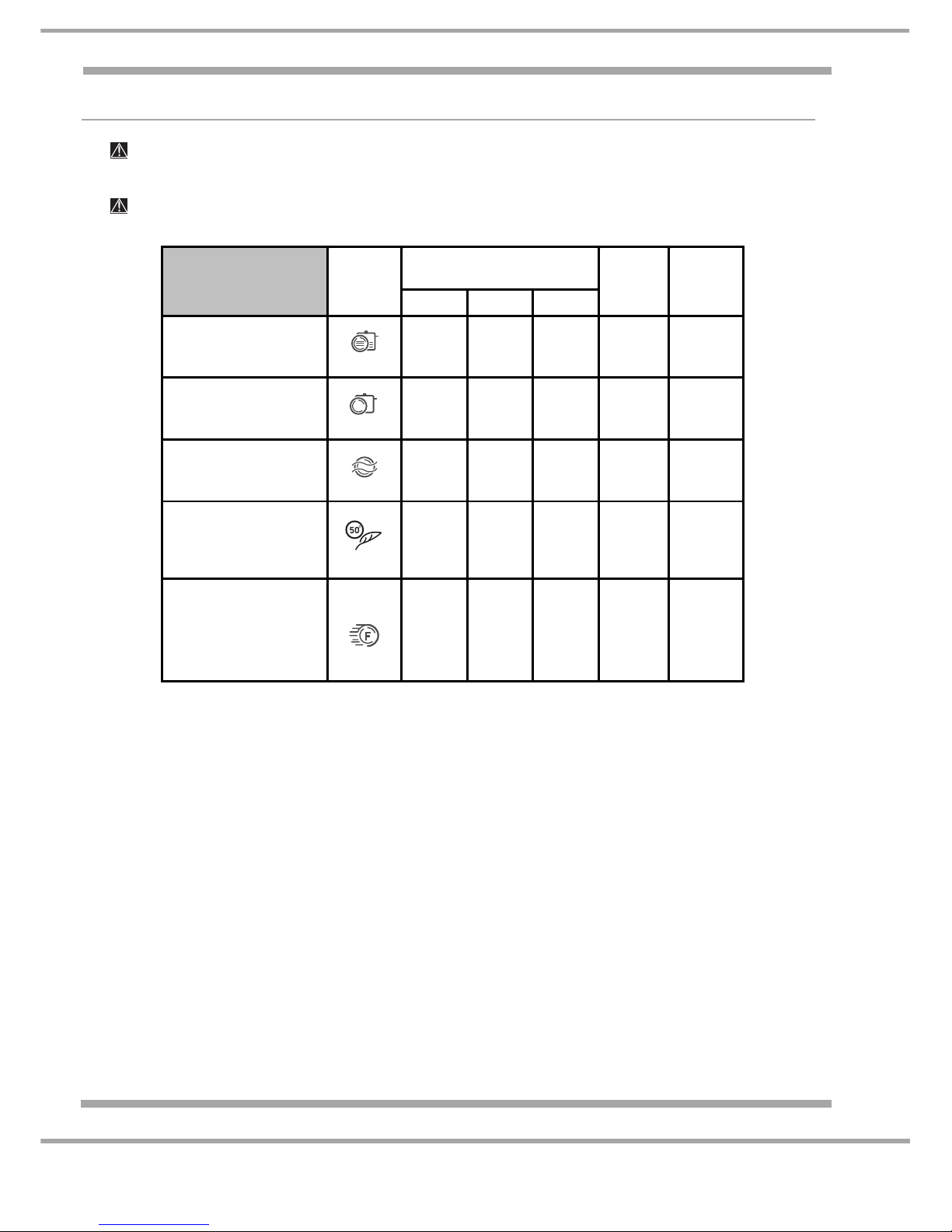
PROGRAMME GUIDE
Notes:
1. Optimum performance levels when using Quick cycle can be achieved by observing the
maximum amounts of crockery specified.
2. * The Eco wash cycle adheres to the regulation EN-50242.
Although it has a longer duration than other wash cycles it uses less energy and is less harmful
to the environment.
3. To make it easier to measure out the detergent, it is worth remembering that:
1 tablespoon = 15 grams of powder = approximately 15 ml of liquid
1 teaspoon = 5 grams of powder = approximately 5 ml of liquid
The number and type of wash cycles and options may vary depending on the dishwasher model.
Detergent
(A) = compartment A
(B) = compartment B
Wash cycle selection
instructions
Wash cycle
Powder Liquid Tablets
Wash
cycles
which
include
drying
Wash cycle
duration
(tolerance
±10%)
Hrs. Min.
Heavily soiled dishes and
pans (not to be used for
delicate items).
Intensive
35 g (A) 35 ml (A) 1 (A)
Yes 2:15’
Normally soiled pans and
dishes. Standard daily wash
cycle.
Normal
29 g (A)
6 g (B)
29 ml (A)
6 ml (B)
1 (A) Yes 1:45’
Pre-wash for dishes while
awaiting completion of the
load with the dishes from the
next meal.
Prewash
No No No No 0:08’
Environmentally-friendly wash
cycle with low energy
consumption levels, suitable
for pans and dishes.
Eco
*
29 g (A)
6 g (B)
29 ml (A)
6 ml (B)
1 (A) Yes 2:35’
Economic and fast wash to
be used for lightly soiled
dishes. (Run cycle
immediately after use) (2
plates + 2 glasses + 4 pieces
of cutlery + 1 saucepan + 1
small frying pan).
Fast wash
25 g (A) 25 ml (A) 1 (A) No 0:35’
If the crockery is only lightly soiled or if it has been rinsed with water before being placed in the
dishwasher, reduce the amount of detergent used accordingly.
Page 7
7 of 35
Indesit Company
Service Manual UK English
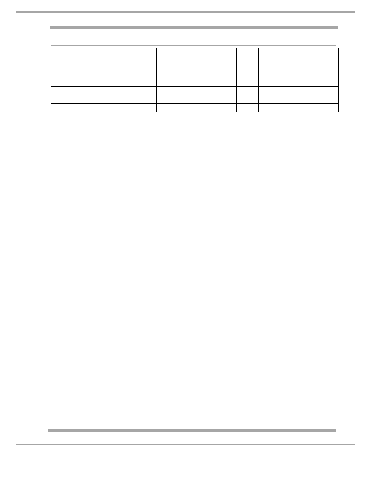
Programme Cycle Sequences
Notes:
1. *The Eco wash cycle adheres to the regulation EN-50242.
Although it has a longer duration than other wash cycles it uses less energy and is less harmful
to the environment.
2. To make it easier to measure out the detergent, it is worth remembering that:
1 tablespoon = 15 grams of powder = approximately 15 ml of liquid.
1 teaspoon = 5 grams of powder = approximately 5 ml of liquid.
BASIC MACHINE USE
Note: Water Hardness MUST be set BEFORE first use or after module replacement.
Refer to following page
Setting a Programme
1. Turn the Machine On (On-Off Button). Start Pause Button Flashes
2. Turn the Wash Cycle Select Knob to the desired Programme.
3. Press the Start Button. The lamp will stop flashing and stay per manently On.
Cancelling a Programme in progress
Press and Hold the ON/OFF BUTTON. All Leds will turn off
End of Programme
The END programme progress lamp will illuminate.
Salt and Rinse Aid Lamps Flashing together
If the salt and rinse aid warning lights flash as well as 1 or more programme progress / delay
and Start lights the machine has a fault. See page 18.
Cycle
Pre-wash 1Pre-wash
2
Wash Rinse 1 Rinse 2
Warm
Rinse
Drying
WITH
water
Drying
WITHOUT
water
INTENSIVE 45°C n/a 63°C Cold Cold 70°C 15 mins 20 mins
NORMAL Cold n/a 52°C Cold n/a 70°C 18 mins 8 mins
PREWASH Cold n/a n/a n/a n/a n/a n/a n/a
ECO* Cold Cold 48°C n/a n/a 70°C 10 mins 40 mins
FAST WASH n/a n/a 50°C Cold n/a n/a n/a n/a
Page 8
8 of 35
Service Manual UK
Indesit Company
English
SETTING THE WATER HARDNESS
These models have 5 Water Hardness Settings to allow for the water supply where the machine is
located.
The Water Hardness Setting must be set:
- before the machine is used for the first time (the factory default setting is 3)
- if a new Module has been fitted or if the machine is moved to a different water area.
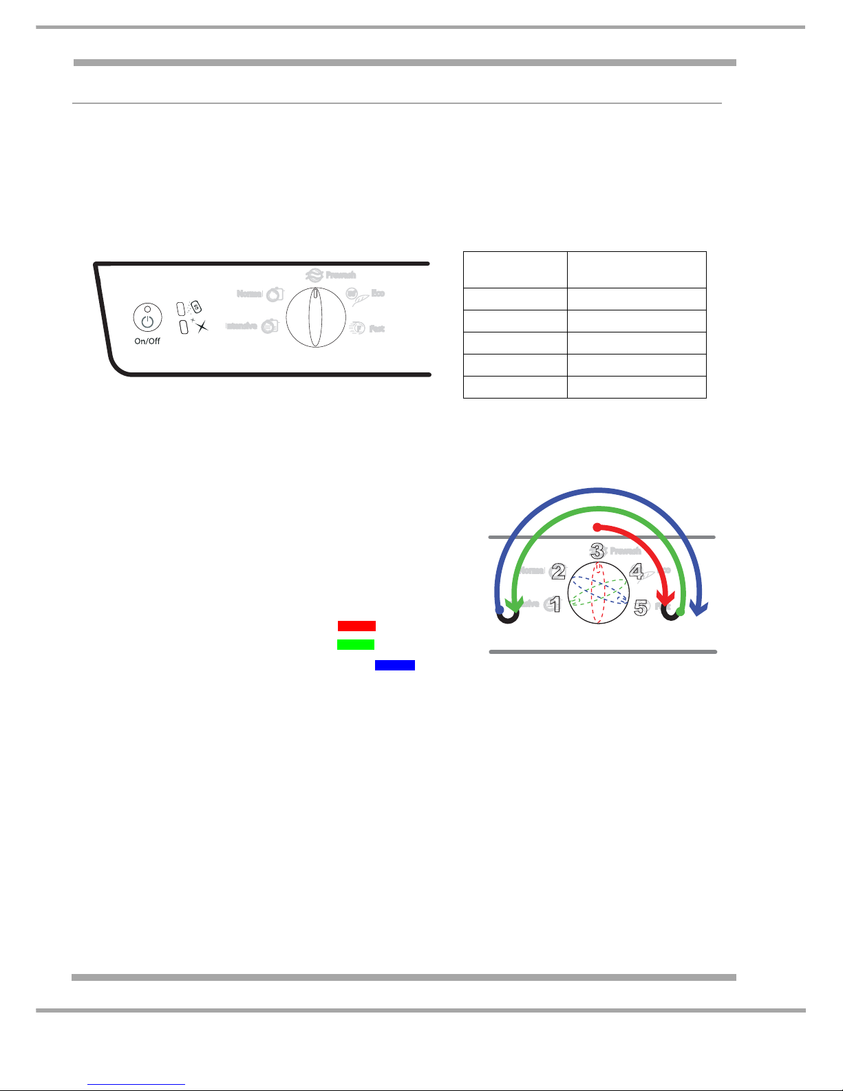
Use the Water Hardness Setting Table above to determine WATER HARDNESS then follow the
following procedure to set the machine to the required Water Hardness.
Note: If the correct Water Hardness Setting is not set, reliability and performance could be
affected.
1. Connect the machine to the mains power supply and
make sure that the power is On.
2. Ensure that the dishwasher is switched Off
(connected to the mains but switched Off at the
console).
3. Close the dishwasher Door and Set the Selector knob
to position 3 (see Fig.1 above).
4. Open the dishwasher Door. (this starts the sequence)
5. Perform the following sequence - see Fig 2
a. Rotate the Selector to position 5
b. Rotate the Selector to position 1
c. Rotate the Selector to position 5 again
d. Switch the machine ON at the console.
e. The Program Progress Lamps should now be Flashing.
f. Rotate the Selector (within 10 seconds) to the required hardness setting (refer to chart
above.) If setting 5 is required, leave the selector at position 5 until the lights stop flashing.
When the lights stop flashing, the setting will be taken from where the selector was positioned.
Note. It is important all steps are carried out with pausing, otherwise the machine will reset to
previous or default setting when the lights stop flashing.
If you fail to complete the sequence within the required time, switch the dishwasher OFF at the
power source and start again from step 1.
Once set, the setting will be remembered even if the power is turned off.
1
2
3
4
5
Fig.1
Water hardness setting table:
Hardness
(Clarke)
Set Hardness
0 - 7 1
7.7 - 14 2
14.7 - 21 3
21.7 - 42 4
42.7 - 63 5
1
2
3
4
5
Fig.2
Page 9
9 of 35
Indesit Company
Service Manual UK English
COMPONENT DESCRIPTION
DEA Power Module
Mounted behind the plinth, this is an e lectronic device th at monitors and c ontrols all dev ices within
the appliance. If replacing this modul e, refer to the Mod ule Programming se ction on in this manual.
DEA601 Module
Fitted from first production to:
FDM554P.R before Serial number 91023.9999, FDM550P.R before Serial number 91231.9999).
DEA602 Module
Used in production - FDM554P.R from Seri al number 91024.0000, FDM550P.R from Serial number
00101.0000).
The pressure and door switches and associated wiring are Low voltage (12 Volts and 10mA) with
RAST 2.5 connector.
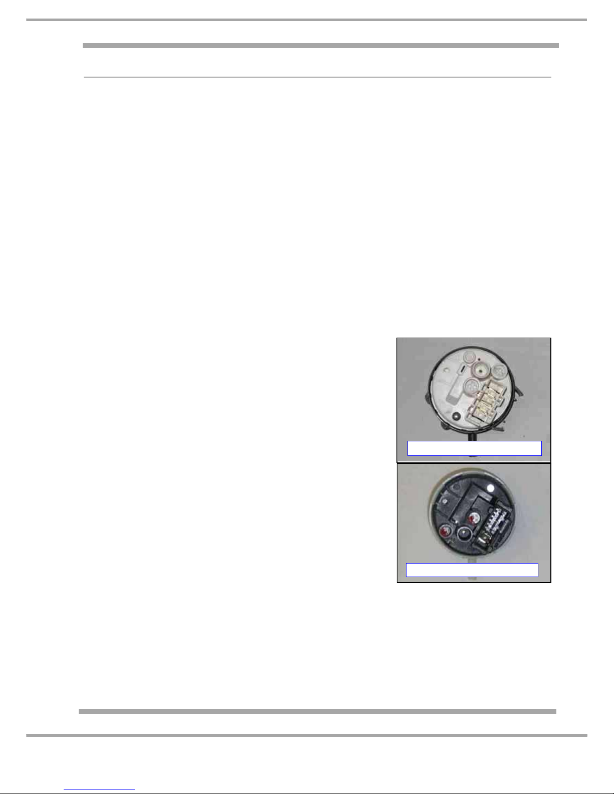
Pressure Switch
The pressure switch controls the overall volume of water inside the tub and signals if the heater can
be turned on. Different types of switch may be fitted depending on which type of Power modue is
fitted.
DEA601 Pressure Switch
Pressure Switch fitted to models with DEA601 module
(FDM554P.R before Serial number 91023.9999, FDM550P.R
before Serial number 91231.9999)
The pressure switch indicates the empty state only (full level not
reached). Full level is signalled when the pressure switch is not
signalling empty.
DEA602 Pressure Switch
Pressure switch fitted to models with DEA602 module
(FDM554P.R from Serial number 91024.0000, FDM550P.R from
Serial number 00101.0000)
The pressure switch and associated wiring is Low Voltage
(12 volts and 10 mA) with RAST 2.5 connector.
The pressure switch indicates the full stat e only (appli ance fill ed
with water).
Empty level is signalled when the pressure switch is not
signalling full.
Fill Valve
The appliance has an electromagneti cally operated solenoid valve, which is connected to the water
supply.
DEA601 Pressure Switch
DEA602 Pressure Switch
Page 10

10 of 35
Service Manual UK
Indesit Company
English
Water Turbine
This is situated at the bottom of the Air Break. Consisting of a fixed reed switch and a magnet fitted
to an impeller. Unlike previous control systems, water fill is no longer dependant on the operation of
the pressure switch. The turbine generates a series of impulses as the water rotates the impeller
vanes.
The control module translates these impulses into litres of fill water (217 impulses is equal to 1 litre
of water). The turbine also regulates the maximum amount of water that can enter the tub, therefore
acting as an overflow device.
Anti Flood Device
Consisting of a polystyrene float and microswitch. An excess of water in the base panel operates the
float switch sending a signal to the control module operating the drain pump and displaying a fault
code on the console.
Filling Sequence
1. Static Fill of 2.5 litres measured by the Fill Turbine.
2. The module checks the state of the Pressure Switch
- if Pressure Switch reaches Full Position - Move to step 3.
- if Pressure Switch at Empty Position - then Pressure Switch Fault Code displays.
3. Dynamic Fill up to 4 litres measured by Fill Turbine.
4. The module checks state of the Pressure Switch.
- if Pressure Switch Full Position reached - Programme Continues to Wash.
- if Pressure Switch at Empty Position, fills with a maximum of 5.5 litres of wate r measured
by Fill Turbine.
If the Pressure Switch is still in the Empty Position, the machine will drain and continues
with the cycle. No Fault Code is displayed.
The Water Level in normal conditions is almost up to the top of the filter.
Key: Static Fill = Fill with Wash Pump Off
Dynamic Fill = Fill with Wash Pump On
Detergent & Rinse Aid Dispenser
Detergent and rinse aid is automatically released during the programme.
The release mechanism is activated by means of a solenoid. This in turn operates a plunger and
lever assembly, thus releasing detergent or rinse aid as required.
The dispenser incorporates a single solenoid.
Providing the dispenser lid is closed before use:> The 1st time solenoid is energised the detergent lid opens (powder or tablet);
> The 2nd time solenoid is energised rinse aid is dispensed.
Note:
Rinse Aid is injected into the machine when the dispenser solenoid is energised and the
detergent lid open.
Drain Pump
This is a separate unit fixed to the sump moulding. It is operated by means of a synchronous motor
and is controlled by the control module.
Page 11
11 of 35
Indesit Company
Service Manual UK English
Heater
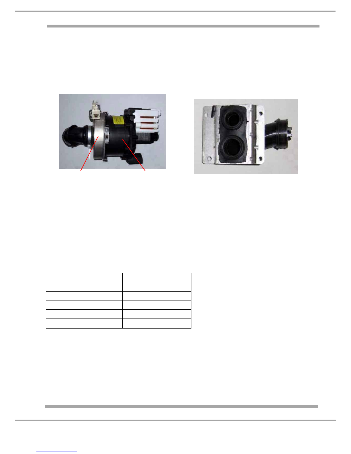
The heater is encased in a metal housing with integral safety cut-out and fuse. It connects to the
Circulating Wash pump housing via a bayonet fitting. Refer to the Circulating Wash Pump description.
Circulating Wash Pump
The motor used is a synchronous motor. The pump housing is connected to the water dispenser,
which feeds the lower and upper spray arms.
Thermistor
Situated on the sump. A temperature rise in the water is converted to a changing resistance value.
A rise in temperature will give a lower resistance across the terminals of the thermistor; the control
module monitors this value and when it is the same as that as defined in the programme selected,
the module will advance the programme out of the heating stage.
Regeneration Procedure
Unlike previous models Regeneration is not carried out during every wash. The Control Module
counts the number of Litres used since the last Regeneration.
The volume of water (in Litres) used between Regeneration is dependant upon the Water Hardness
Setting stored in the Control Module. (Refer to "Setting the Water Hardness"). See Chart below.
Regeneration Sequence
1. Regeneration valve activated, after 2 seconds, the fill inlet solenoid is opened to allow water
flow, water flows from the inlet through the salt and the mixture of water and salt reaches the
resins.
2. Solenoid valve closes (the inlet valve and after 2 seconds the regeneration valve)
3. Pause for 10 minutes
4. Fill with 190cc of water. (same procedure as step 1.)
5. 5 minutes pause
Circulation Wash Pump Assembly
Water Dispenser
Water Hardness Setting Regenerates Every...
No water is stored for Regeneration and
regeneration will always take place at
the end of last rinse, after the number of
litres has been achieved.
1 150 litres
2 100 litres
3 65 litres
4 30 litres
5 15 litres
Heater Assembly Pump Motor
Page 12
12 of 35
Service Manual UK
Indesit Company
English
6. Starts resin wash. Between 1 and 2 litres of water flow directly thro ugh the resins. (Inlet valve is
on, regeneration valve is off.
7. Drains. Note: Regeneration time is hidden within the cycle so does not affect programme
times.
Low Salt Warning
An Optical sensor is fitted to the salt container where the presence of salt breaks the beam in the
sensor. When the level of salt is below the sensor level, the receiving sensor receives the light beam
from the sending Led. The Low Salt warning lamp is switched on 6 washes after the sensor signals
the module.
The sensor position is not at the bottom of the salt container because of possible false readings
caused by impurities that collect in the bottom of the salt container.
Note: Whenever the low salt warning lamp is on, the dishwasher will not carry out
regeneration.
Low Rinse Aid
A float is fitted into the rinse aid dispenser, when the level of the float is near the bottom of the rinse
aid reservoir the float will trigger a signal to the Contro l Module to turn on the Low Rinse Aid Warning
Lamp.
Air Break Assembly
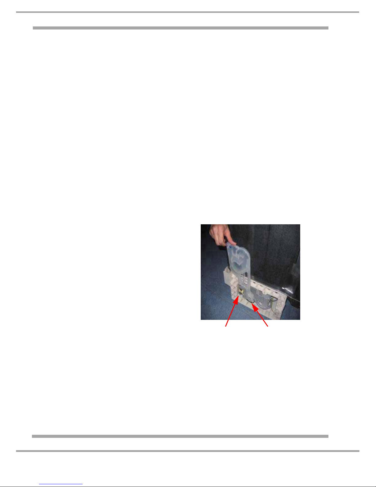
Located on the right hand side of the machine.
The Air Break Assembly carries out 3 functions
1. Stops filling water siphoning back into the mains
water supply.
2. Vents the Steam from the dishwasher tub.
3. Diverts 3% of the hard water fill into the tub to
avoid the water being too soft which could
cause excessive foam.
The Air Break also holds the regeneration valve
and the Water fill turbine.
Regeneration
Fill Turbine
Valve
Page 13
13 of 35
Indesit Company
Service Manual UK English
Drying
The Natural Drying System uses Residual Heat and Rinse Aid to Dry loaded dishwasher.
During the Drying Phase of the cycle the Water reaches a very high Temperature 70
°C,.
Drying is carried out in 2 steps both with the machine paused (Circulating wash pump off)
1. Hot water in the tub
2. Hot water drained from the tub
All models - These times should be used as a guide only, as the Programme settings files are
continuously being updated.
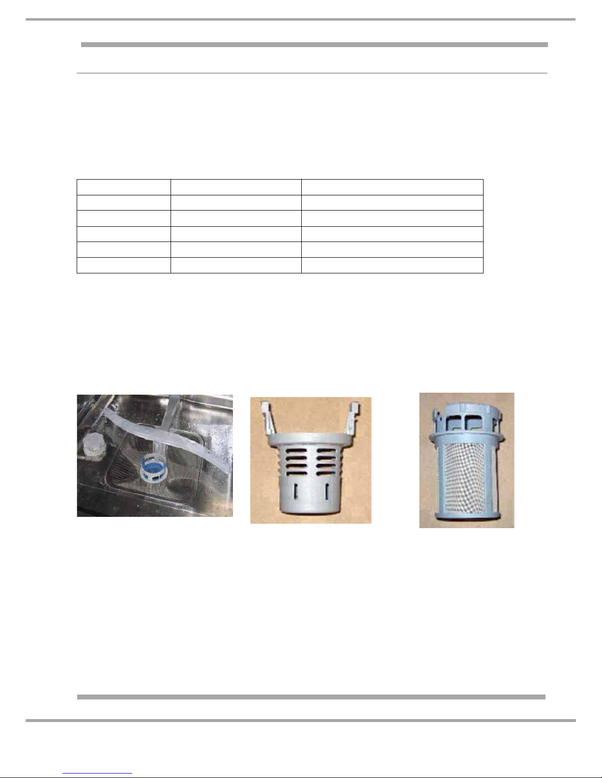
Filtering System
The flat filter is made of metal and larger than previous models which will prevent the filter from
clogging.
Cycle Drying with Water Drying without Water
Intensive 15 minutes 20 minutes
Normal 18 minutes 8 minutes
PreWash n/a n/a
Eco 10 minutes 40 minutes
Fast Wash n/a n/a
Flat Filter
Bowl Filter
Micro Filter
Page 14
14 of 35
Service Manual UK
Indesit Company
English
FAULT CODES & DIAGNOSTICS
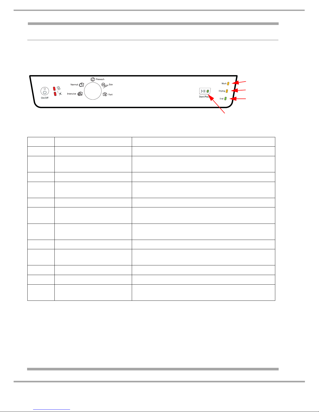
If an error is detected in programme , the programme will be terminated and one of the following errors
will be displayed using a combination of the programme LED’s on the console panel.
The relevant LED(s) will flash in the event of a fault. The On/Off LED will also flash.
Fig. 1 identifies the programme progress LED to the corresponding LED shown in the fault code chart.
• Note 1. If the water is turned off after approximately 2 minutes the machine will beep every 2 seconds,
then display a fault code.
• Note 2. In the event of any of the above codes being displayed, after the fault has been rectified it will
be necessary to reset the dishwasher.
Resetting after a fault
This is achieved by switching OFF the dishwasher with the On/Off switch and waiti ng 30 seconds. The
dishwasher is then ready for use.
LED
Fault Possible Cause(s)
1
Overflow (water in base pan). Leak from water line.
2
Valve or Turbine faulty or
disconnected.
Inlet valve, connections, valve letting water pass through
when off.
3
Thermistor circuit Thermistor / module.
4
Time out heating Heater Open circuit or NTC thermistor detached from
casing.
1 + 2
Time out draining Pump connections, blockage, module, circulation pump.
2 + 3
Time out filling Customer's tap, Inlet valve, connections, timer, water
turbine.
1 + 3
Pressure Switch Mesh plate, filter or microfilter, pressure switch,
circulation pump.
1 + 4
Software recognition error Module not programmed, wrong keypad
2 + 4
Heating circuit Heating element, connections, module, relay, pressure
switch.
3 + 4
Communication Error
1 + 3 + 4
Non-operative module
1 + 2 + 3
Turbine faulty Module has detected no Turbine rotation. check turbine
and wiring
N.B. In a Fault condition the Salt & Rinse Aid lights will also flash
LED 1
LED 2
LED 3
LED 4
Fig.1
Page 15

15 of 35
Indesit Company
Service Manual UK English
Possible Reasons for Fault Code Displayed
Note: - Always carry out an earth insulation test before using the fault guide, as an earth fault on a
component or damaged wiring may display fault codes not related to the component signalled.
If any earth faults are found on initial testing they must be rectified before using the fault code chart,
to avoid erroneous codes being displayed.
Modern components, especially modules are very reliable, therefore edge connectors, contacts and
wiring should be thoroughly tested before trying components.
LED 1The micro-switch in the base tray has been closed for 9 seconds to signal the alarm.
Water is leaking from components or hoses in the base of the machine.
Programme will abort and the drain pump will be energised.
LED 2The module has detected movement of the turbine for 9 seconds when the inlet valve was not
energised.
The inlet valve is letting water by when the valve is closed.
The programme will be aborted and the drain pump is energised.
LED 1 & 2 The drain pump has been energised for 8 minutes, but the pressure switch has not
switched to the empty position (contacts 11-12).
• Check continuity of the pump coil.
• Check for a jammed drain pump or blockage in the outlet hose or plumbing.
• A blocked pressure chamber or pressure switch air tube.
• Check the pressure switch operation.
• Check wiring to pump and module connections.
LED 1, 2 & 3 The module has detected no turbine rotation
• Check wiring between turbine and module.
• Check Turbine rotation
LED 1 & 3 Pressure Switch
The machine has filled with 2.5 litres of water but the pressure switch is still in the
empty position.
• Check the filter or sump is not blocked.
• Check the pressure switch is not stuck in the empty position (contacts 11-12) or the
pressure chamber or air tube are either blocked, unattached or split.
• Check the wash pump is circulating the water.
• Check the wiring to the pressure switch.
• Check the edge connector blocks on the pressure switch and module card.
• Check the outlet hose is not too low causing the machine to siphon.
• Aborts the cycle and energises the drain pump.
LED 1 & 4 Module recognition error.
• Check edge connections and wiring.
• Reprogramme the EEPROM file.
• Replace module or display as required.
LED 2 & 3 Time out for filling.
(The WASH LED will flash as a warning before the fault code is displayed.)
The module has not detected turbine rotation with the inlet valve energised.
• Check the taps are turned on and that the fill hoses are not kinked.
Page 16

16 of 35
Service Manual UK
Indesit Company
English
• Check the inlet valve coil (4k ohms approximately) and wiring to valve and edge
connector on module.
• Check the wiring and connector blocks to module, inlet valve and turbine.
• If all above tests are OK, replace turbine or module as required.
Aborts the cycle and energises the drain pump.
LED 4Time out for water heating.
The module has not detected temperature increase in 60 minutes.
• Check that the thermistor is not detached from its sump pocket.
• Check that the heater is not open circuit.
• Check if the wash pump is not circulating the water.
• Check the element is heating, and the TOC is not opening after a time .
• Note: The heater has self-resetting cut-out (95
°C) and a thermal one-shot fuse (206°C).
LED 2 & 4 Open circuit in heating circuit.
• Check the circuit of the heating element (30 Ω).
• Check for an open circuit heater cut-out or fuse.
• Check pressure switch circuit (connections 11-14).
• Check wiring and connections between module card, pressure switch and heater.
• If all above is OK, replace module card. Note: the module will need reprogramming after
replacement.
LED 3 & 4 Communication Error
• Check connection and continuity of cable / connectors on lead between LED Display and
Control Module
Page 17

17 of 35
Indesit Company
Service Manual UK English
Fault Notes
It is recommended BEFORE a module is replaced or when the fault is not obvious, the
heating element is tested for continuity and resistance t o earth at its terminals, with the
heater disconnected.
• Blocked Filter
There is NOT a fault code for a blocked filter. The large surface area of the filter makes a
blocked filter very unlikely. If the filter was completely blocked, and the pressure switch had
not moved to the FULL position after a maximum fill of 5.5 litres of water, the machine will
drain and continue with the cycle. The symptoms of a blocked filter would be Poor Wash
Results and a very quick cycle.
• Filling
After the initial drain period, it is normal at the start of a cycle for the machine to pause for a
period before filling.
• Wash Pump
There is no fault code for a faulty wash pump.
A faulty wash pump may display the timeout heating fault code.
• Heating Element
An open circuit heating element can display either the heating time out fault code (LED 4) or
the open circuit heater fault code (LEDs 2 and 4), depending on the cycle in progress
or the phase of the cycle when the heater fails.
If a dishwasher has an open circuit heat ing element, the machine may run for up to 75 minutes
before a fault code will display.
• Noise
Excessive foaming can cause the machine to sound excessively noisy, after the programme
has been running for a short period.
Excessive foaming usually happens when using multi function tablets to wash a small or
lightly soiled load. Multi function tablets are a 1 dose detergent etc. for a normally soiled full
load. Before loading the dishwasher, it is important only large food items are removed from
the plates and they are not rinsed.
• Programme Times
The times in the handbook and displayed at the start of the cycle, are average times and will
be affected by the following points:
• Inlet water temperature below 19°C
• Tab option enabled
• Water hardness setting set to positions 4 or 5
• Condition of the heating element (limescale built up)
• Excessive foam caused by using tablets with a small or light load.
NOTE: - The display is not a count down timer. It is normal occasionally for the same time to
show for an extended period.
• Machine Starts up for a few minutes when not in use
The machine inlet valve is 'letting by' and water is leaking into the machi ne wh en no t in use .
Providing the machine is plugged in and the door closed (it does not have to be switched on),
once the water in the machine is enough to operate the pressure switch to full level, the
machine drain pump will energise until the pressure switch resets to empty (plus 30 seconds).
Note: - Fault Code LED2 displays if the water letting by is fast enough to be recognised by
the water turbine. Refer to page 15 for more information.
Page 18

18 of 35
Service Manual UK
Indesit Company
English
Test Programme
A short test programme is available.
This test will display a previous fault code if there is one.
The test will check many of the components and filling and if faulty, will display a fault code quicker
than running a cycle.
It is useful for quickly checking several components, e.g. wash pump, fill valve, detergent solenoid,
regeneration valve and drain pump and also water levels.
Fault diagnosis could in many instances still be required.
To enter the Test Mode
Start with the appliance off and the door closed.
1. Switch the dishwasher 'on' (On/Off button).
2. Switch the dishwasher 'off' (On/Off button).
3. Press the Start button and hold for 3 seconds.
4. Switch the dishwasher 'on' (On/Off button).
5. Press start.
When the Auto Test starts the last fault will be displayed for 15 seconds.
This will clear if the Auto Test is fully completed.
DEA601 Module - Auto Test Sequence
All times are approximate.
1. Draining until the pressure switch is empty + 30 seconds.
2. Static filling 3 litres of water (valve energised only).
3. Dynamic filling 1 litre of water (valve + wash pump energised).
4. Wash pump on for 60 seconds.
5. Wash pump stops.
6. Heater on for 10 seconds.
7. Dispenser solenoid energised for 10 seconds.
8. Wash pump on for 10 seconds.
9. Regeneration valve on for 15 seconds (a slight hum will be heard).
10. Drain pump on until the pressure signals machine empty + 5 seconds.
11. Pause for 10 seconds.
12. Inlet solenoid valve and pump running simultaneously for 20 seconds.
13. Test cycle complete.
DEA602 Module - Auto Test Sequence
refer to next page...
Page 19

19 of 35
Indesit Company
Service Manual UK English
DEA602 Module - Auto Test Sequence
All times are approximate.
At each stage if "time out" occurs then a fault code will display, but if the task is completed
within the correct time, the Test will move to the next task.
1. Drain until empty + 15 seconds (90 second Time out, when fill time out alarm will display)
2. Fill until Turbine registers 2 litres and Pressure Switch Full. (timeout = 120 seconds, when
alarm will display).
3. Wash Pump on, which will activate Pressure Switch to Empty (timeout 25secs), wash pump,
will run for about 2 seconds).
4. Wash Pump Off
5. Fill up to 4 Litres of Water (time out 120seconds, whem fill alarm will display)
6. Wash Pump on for 30 seconds
7. Wash Pump and Heater on
8. Raise Temperature to 30'C (timeout 10 minutes, when Heating timeout alarm will display).
9. Drain Pump on until empty plus 10 seconds (timeout 90 seconds, when pump alarm will
display)
10. Activation of Dispenser Solenoid for 15 seconds.
11. Regeneration Solenoid plus Fill solenoid 15 seconds
12. Drain Pump on until empty Pressure Switch plus 10 seconds. (time Out 90 seconds, when drain
pump alarm will display).
13. Test cycle complete.
Page 20
Indesit Company
20 of 35
Service Manual UK English
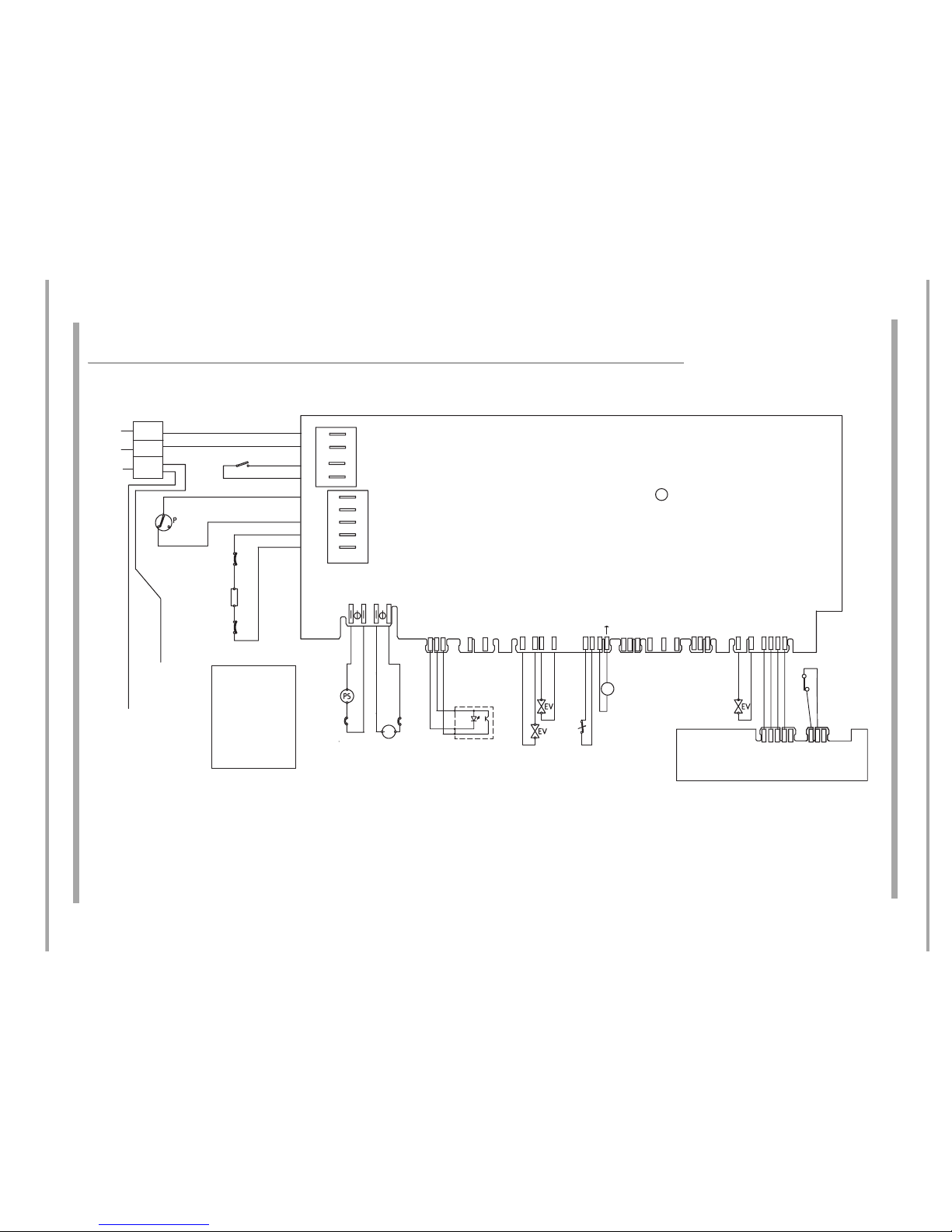
WIRING DIAGRAM - DEA 601 Module
FDM550P, FDM550P.R, FDM550P before Serial No. 91231.9999 & FDM554P.R before Serial No. 91023.9999
CN01
CN04
CN11
CN05
CN06
CN07
CN08
CN02
CN03
1
1
1
LINEA IP
DISPENSER
T.F. (206°)
n.c.
R
n.c.
ITR(95°)
14
11
1
RR
RR
1
L
S
1
LINEA
POMPASC
LINEA IP
POMPA LAV
LINEA IP
LINEA IP
RIGENERA
EVCARICO
H2OSTOP
REF
TURBINA
CL
SDA_BUS
SCL_BUS
GND
REF
1
SDA
_BUS
SCL_BUS
GND
REF
11
GND
INPUT
+
V
C
C
1
T
X
+
V
C
C
R
X
+
1
2
V
O
L
T
R
X
T
X
N
E
U
T
R
O
T
R
I
A
C
A
L
T
.
L
I
N
E
A
_
I
P
S
ML
TIMER DEA 601
Regen
Valve
Fill
Valve
Dispenser
Rinse Aid
Reed
Switch
USER
INTERFACE
CONTROL PCB
Turbine
Salt Sensor
Drain
Pump
Wash Pump
Motor
Aqua Stop
Switch
LIVE (CN01- 2 )
NEUTRAL (CN01- 1)
LIVE SWITCHED (CN01-3 )
LIVE IP (CN01-4)
LIVE IP (CN02-1)
FULL (CN02-2)
EMPTY (CN02-3)
HEATER (CN02-4)
HEATER (CN02-5)
Door Switch
Pressure
Switch
Heater
Key:
IS = Door Switch
P1 = Pressure Switch
R = Heater
PS = Pump
ML = Wash Pump
EV = Water Valve
CL = Turbine
S = Thermal Fuse ?
Heater
Body - Earth
Chassis
- Earth
N
E
L
220/240V
50 HZ
Page 21
Indesit Company
21 of 35
Service Manual UK English
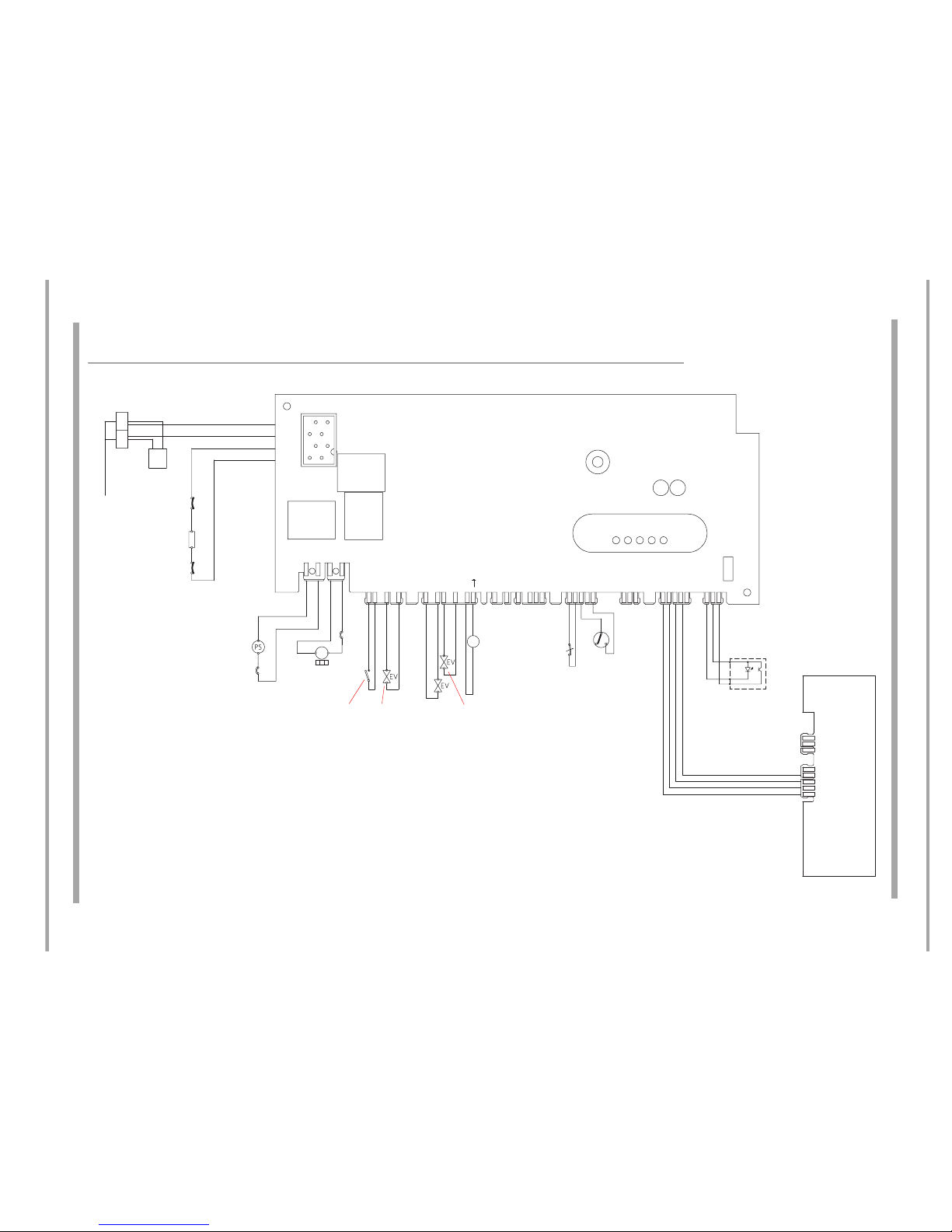
WIRING DIAGRAM - DEA602 Module
FDM550P.R models from Serial Number 00101.0000 & FDM554P.R models from Serial Number 91024.0000
CN01
CN04
CN05
CN06
CN07
CN08CN03
LINEAI P
DISPENSER
IN LINE
SUPPRESSOR
DRAIN
PUMP
FILL
VALVE
SALT
SENSOR
AQUA STOP
SWITCH
REGENERATION
VALVE
USER INTERFACE
CONTROL PCB
LOW VOLTAGE
DOOR SWITCH
LOW VOLTAGE
PRESSURE SWITCH
SYNCHRONOUS
DRAIN PUMP
HEATER
DISPENSER
TURBINE
NEUTRAL (CN01-2)
LINE (CN01-1)
RR T.F. (CN01-3)
RR ITR (CN01-4)
N
L
F
MR
T.F. (206°)
n.c.
R
n.c.
ITR(95°)
1
L
S
1
LINEA
POMPASC
LINEA IP
POMPALAV
LINEA IP
LINEA IP
RIGENERA
EVCARICO
TURBINA
CL
SDA_BUS
SCL_BUS
GND
REF
1
SDA_BUS
SCL_BUS
GND
REF
11
GND
INPUT
+
V
C
C
1
T
X
+
1
2
V
O
L
T
R
X
+
1
2
V
O
L
T
R
X
T
X
N
E
U
T
R
O
T
R
I
A
C
A
L
T
.
L
I
N
E
A
_
I
P
S
ML
TIMER DEA602
220/240V 50 HZ
1
O
N
/
O
F
F
1
ON/OFF
M
I
C
R
O
P
O
R
T
A
1
2
V
O
L
T
111
1
P
R
E
S
S
U
R
G
N
D
+
5
/
+
1
2
V
O
L
T
+
1
2
V
O
L
T
H
2
O
S
T
O
P
14
11
P1
1/5 3/7 4/8 5/9
CN09
CN02
5407478wd2.pdf
16002532500
Page 22
Indesit Company
22 of 35
Service Manual UK English
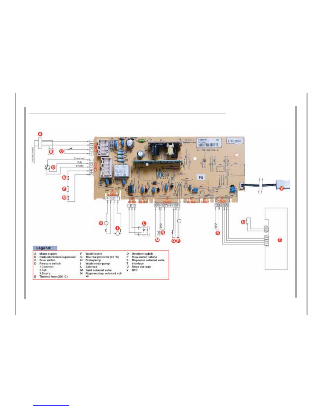
WIRING DIAGRAM with module photo
Page 23
23 of 35
Indesit Company
Service Manual UK English
Module Programming
The module will always be supplied without a programme when supplied as a spare part.
NOTE: This board does not have a physically replaceable Eeprom.
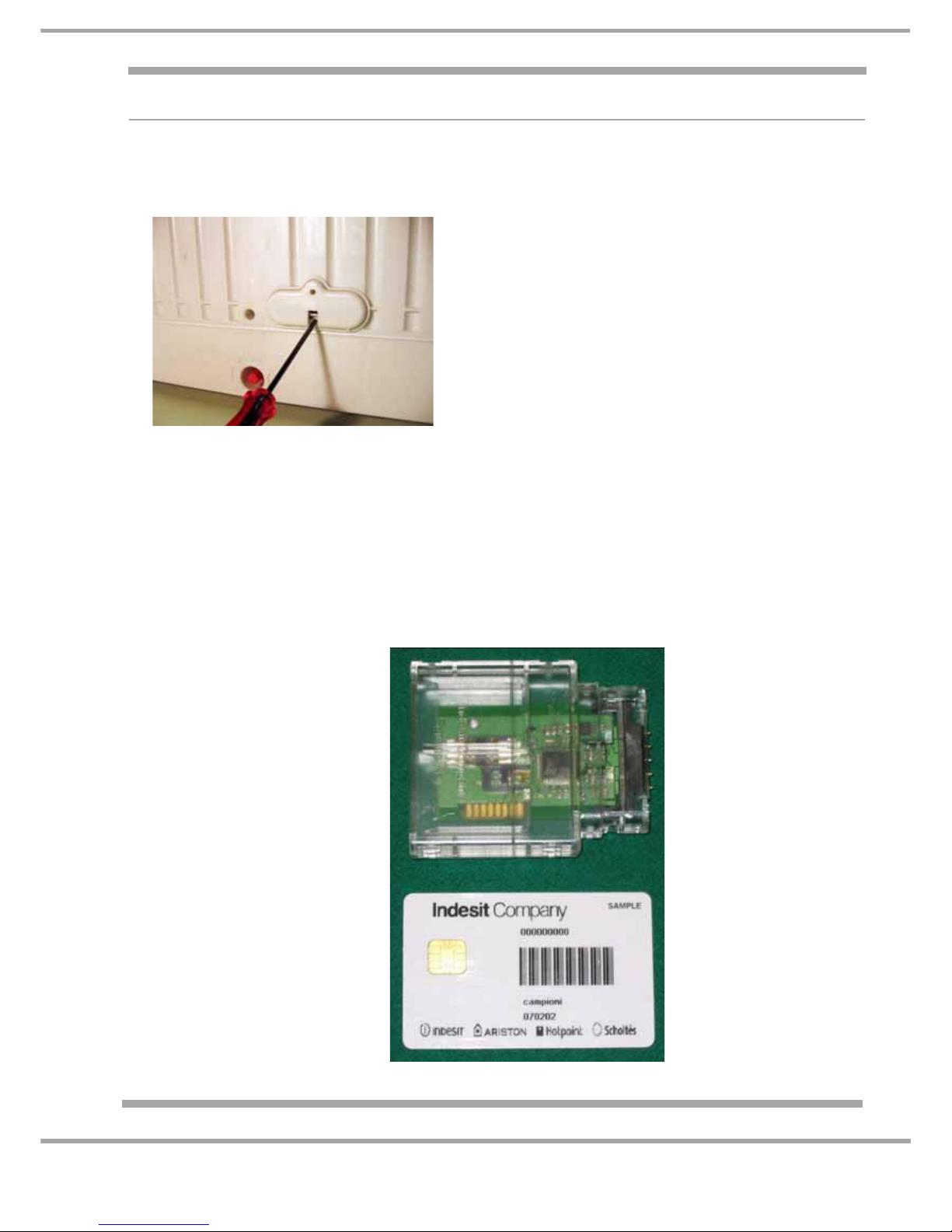
Programming Access Panel - situated beneath the Dishwasher Door.
Programming a Module:
There are a number of ways the board can be programmed - some of which are not applicable to
certain markets.
Types of programming:
1. Handheld Terminal (Not UK)
2. Emit / Memwriter (UK Indesit Service Engineers)
3. Smart Reader & Smart Card (certain area's of UK market) see photo below.
use a small flat bladed screwdriver to release the panel.
Smart Card Reader
Smart Card
this card holds the EEPROM
program file and can only be
used ONCE.
This holds the smart card.
It is the interface between
the smart card and the module.
Page 24
24 of 35
Service Manual UK
Indesit Company
English
PROGRAMMING (Using EMIT)
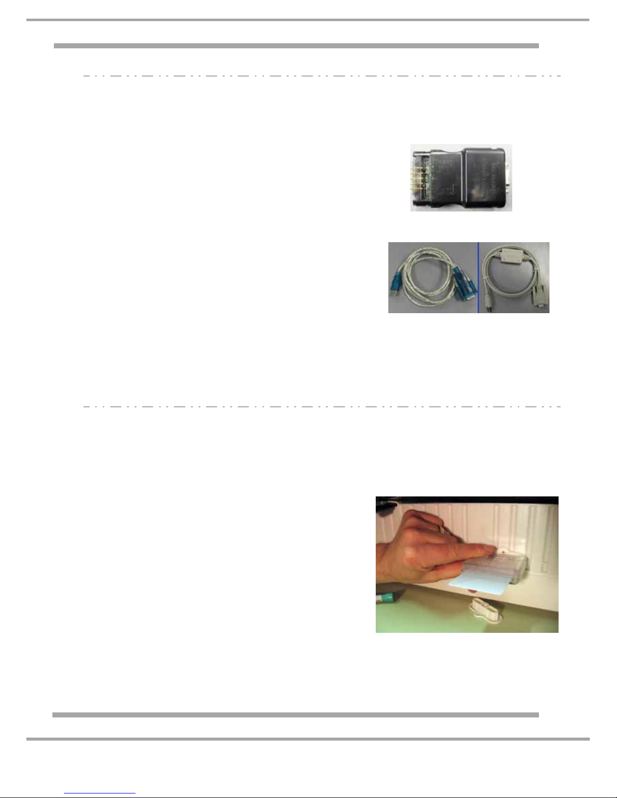
These dishwashers can be programmed via the Emit, using a USB lead (Part number C00222800),
Hardware key (Part number C00115587) & the Memwriter software.
You MUST hold the Reader in place whilst programming is taking place.
PROGRAMMING (Using Smartcard Reader / Card)
If the Main Module has been replaced during a repair the module will require programming using
the following method.
1. Select Memwriter programme.
2. Ensure correct Valid Comport is selected.
3. Ensure correct Hardware key is selected (Black).
4. Ensure correct Appliance type is selected (New Platform)
5. Select Commercial Code.
6. Open Comm Port (A bright green connection icon will light
on screen).
7. Click into CODE BOX in "Search Method".
8. Insert Commercial Code & Serial number.
9. Click search button.
10. File to download box's will now display machine
information.
11. Click download.
If appliance already has the most upto date file a warning
box will appear indicating EEPROM ALREADY UPDATED
NOTE: When starting Memwriter programme the default
selection is always GET FROM HARDWARE.
Black Hardware Key
USB - Serial Cable
A Hardware Key Pin Repair Kit is
available which contains
5 replacement pins
(order Part No. C00114723).
1. Do NOT connect the machine to electrical supply.
2. Insert the pre-programmed card into the Card reader.
Care must be taken at this point to ensure the card is
inserted correctly with the Chip on the card facing the
PCB of the Reader.
3. Insert the Reader & Card into module connection port
- see photo. You MUST hold the Reader in place
whilst programming is taking place.
4. Connect the machine to the Electrical supply, the
LED's on the Smart Card Reader will light in this
sequence:
a) Red OFF: Good Communication between Smart Card
Reader & Card.
b) Red OFF; Green Blinking: Download taking place.
c) At end, Green ON ---> Download OK.
d) At end, Red ON ---> Download NOT OK.
5. Programming Comple te, disconnect the machine from
Electrical supply.
6. Remove the Smart Card Reader.
Smart Card Reader
and Smart Card in use
You MUST hold the Reader in place whilst
programming is taking place.
Page 25
25 of 35
Indesit Company
Service Manual UK English
DISMANTLING INSTRUCTIONS
SAFETY NOTES:-
1. ENSURE THAT THE MACHINE IS UNPLUGGED BEFORE DISMANTLING
2. BEWARE OF SHARP EDGES ON METAL PANELS AND PRESSED PARTS.
Access to all components are via the side panels, front plinth or the access panel in the base tray.
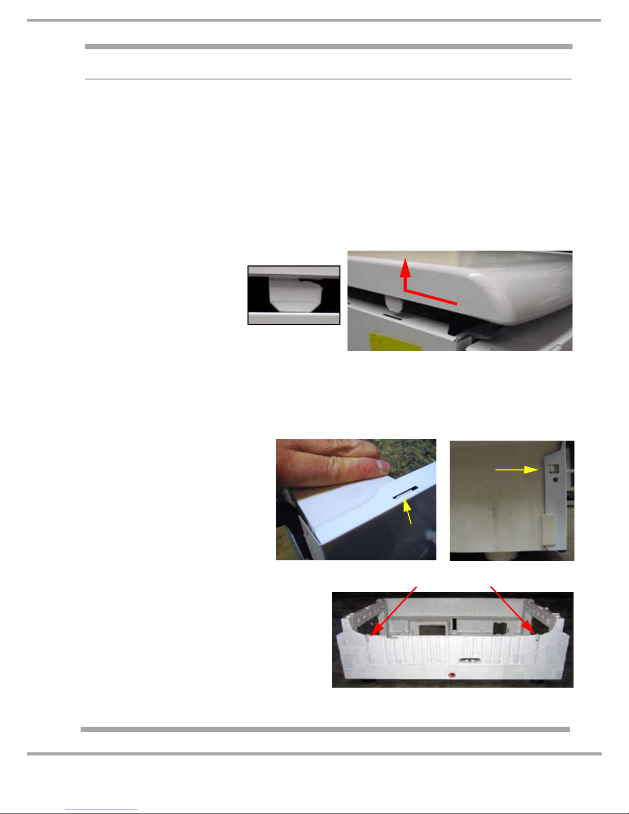
A Plinth and Side Cheek Assembly
1. Fully open the Dishwasher Door
2. Remove the screw securing each side cheek to the dishwasher cabinet.
3. Carefully lean the dishwasher back slightly to remove the Plinth side cheek assembly.
B Worktop
C Outer Door Panel
1. Remove screws along each side.
2. Disengage the front panel from the console locating lugs.
3. Slide the Outer Door panel down to release from Console Lo cating Lugs.
4. When Refitting carefully engage all fixing lugs on the console.
1. Remove the Rear 2 Fixing Screws
2. Slide the worktop toward
the back to release the
hooks from the slots in the
cabinet side panels. (2
hooks each side)
3. Lift up to remove. Hooks (4)
D. Side Panels
1. Remove the 6 screws securing
the side panel. (3 front, 3 rear)
2. Using a flat bladed screwdriver,
ease the panel over the location
pegs and lift away
NOTE: Side clips at Base and
Upper Support.
E. Front Access Flap
1. Remove 2 securing screws
2. Release 2 locking Clips
3. Carefully open Flap releasing wiring
harness from top edge.
Note: (The Control Module is attached to the
flap)
4. When refitting be careful not to trap any
wires.
Release access flap locking tabs
Upper Support
Clip
Base Clip
(Rear)
Page 26
26 of 35
Service Manual UK
Indesit Company
English
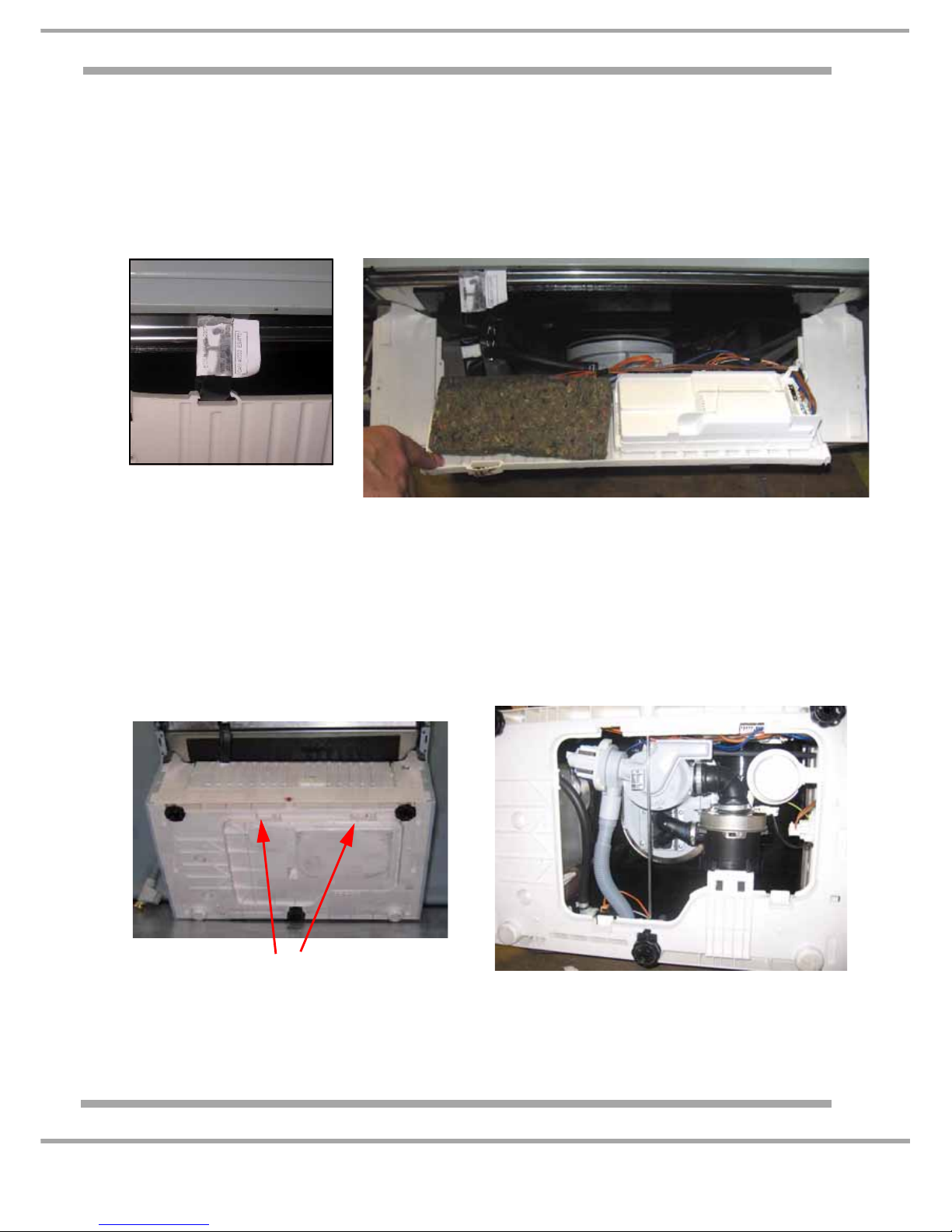
F. Power Module
1. Release front access flap as in E). and release harness retaining clip before hinging down.
2. Slide power module towards connections to release from access panel.
3. Note position and remove connections.
4. Release board from carrier.
Note: A Service Module is supplied WITHOUT a programme loaded.
Refer to the Module Programming section in this manual.
Ensure that the harness is
clipped back into place when
the flap is closed
Front Access panel opens out with Control Module Attached.
G. Base Unit Access Panel
1. Protect the customers flooring
2. Being careful not to damage the waste hose carefully lay the machine on its back.
3. Remove any screws that may have been fitted to replace broken clips.
4. Release 2 fixing clips on front edge.
5. Ease panel forwards releasing lugs from rear of panel.
Locking Tabs
Access panel removed
Page 27
27 of 35
Indesit Company
Service Manual UK English
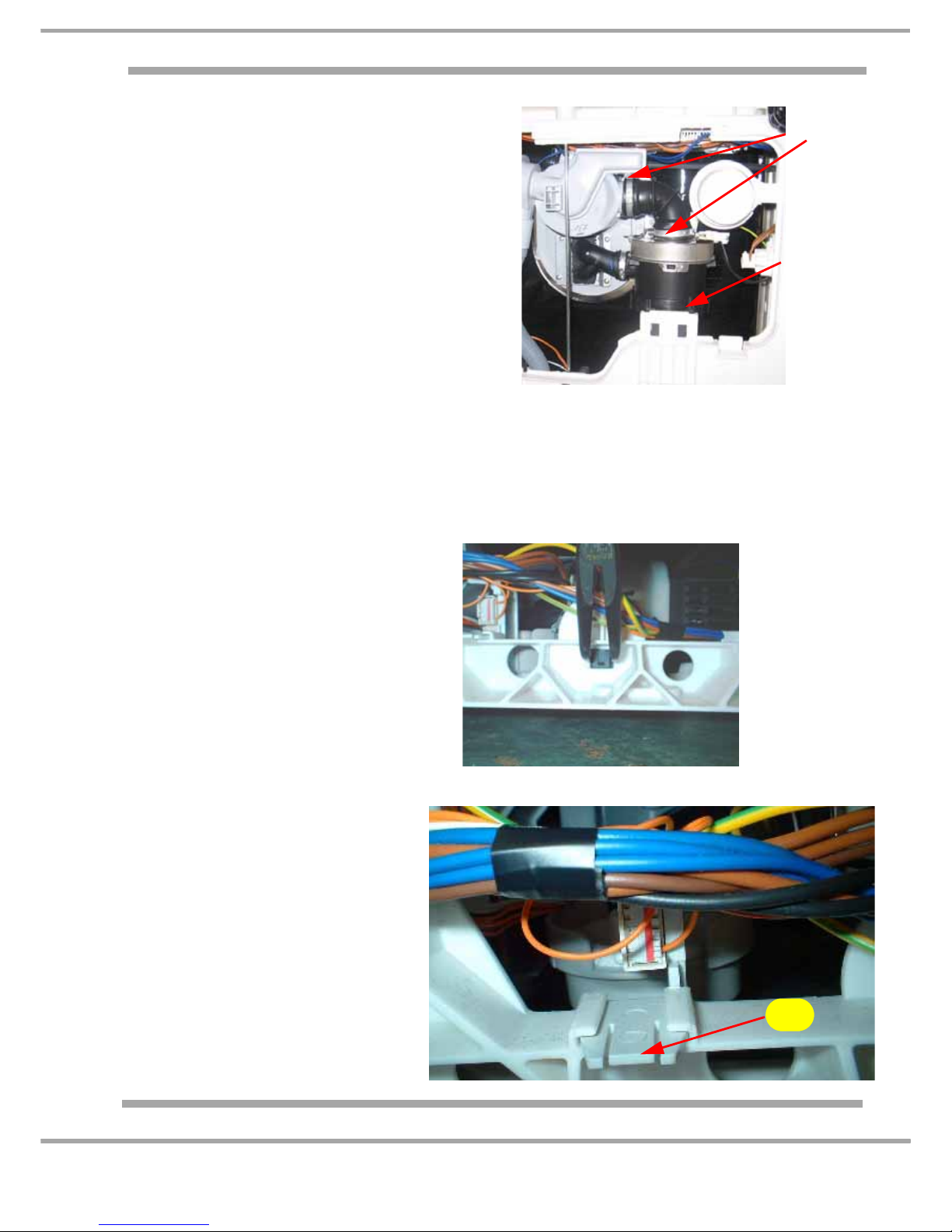
H. Circulating Motor & Heater
1. Remove base access panel as in G).
2. Release 2 hose clips and hoses.
3. Ease motor towards front away from mounting
bracket.
4. Separate motor from heater by twisting in a
anti clockwise direction.
5. Important
On reassembly:-
a. Do not reuse the removed hose clips.
Replace with new clips C00196223.
b. Ensure 'O' ring is correctly positioned to
avoid leaks.
I. Drain Pump
1. Remove base access panel as in G).
2. Release drain hose by gently pulling away from pump.
3. Twist pump motor anti-clockwise to release it from the sump.
4. Ensure 'o' ring is positioned correctly to avoid leaks.
J. Pressure Switch
1. Facing the front of machine remove r/
h side panel as in D)
2. Using suitable pliers squee ze cli p and
release pressure switch
3. Disconnect wiring.
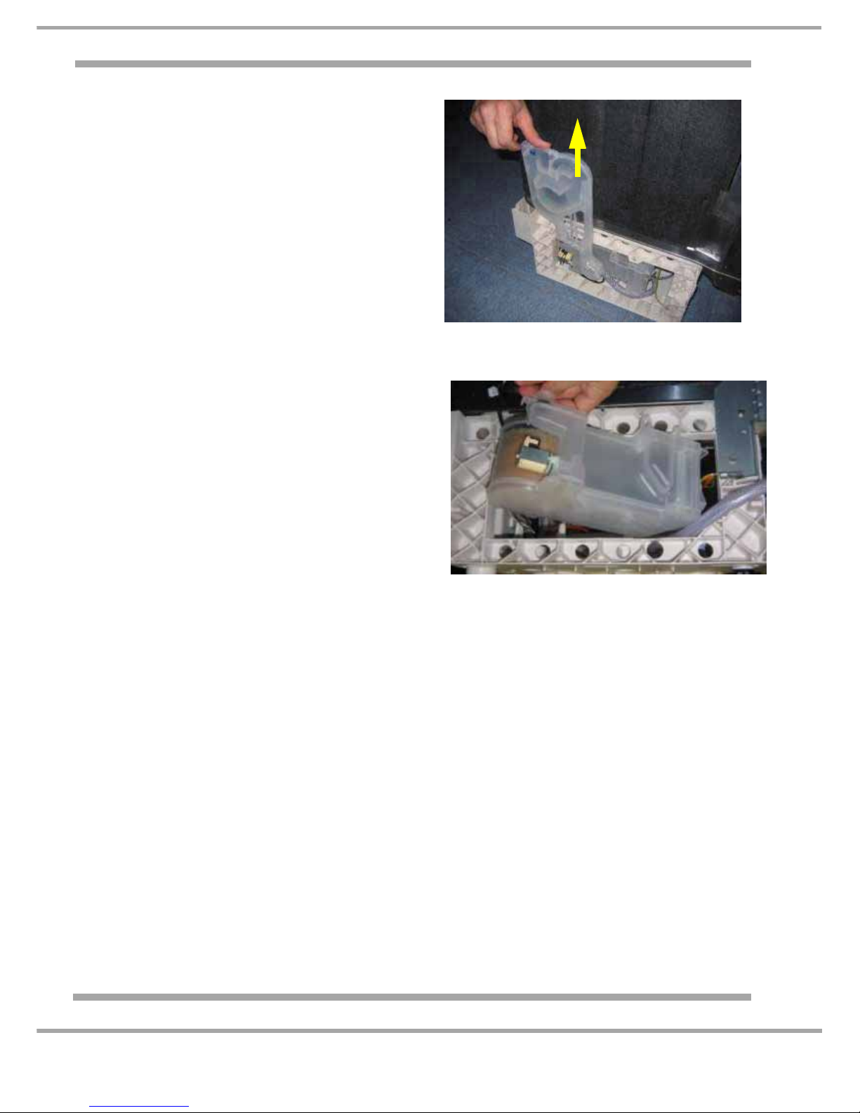
K. Overflow Unit
(base float switch)
1. Facing the front of machine
remove r/h side panel as in D).
2. Release clip and slid unit from
base frame.
3. Disconnect wiring.
4. Float and switch can now be
separated from unit.
Hose
Clips
Mounting
Bracket
Clip
Page 28
28 of 35
Service Manual UK
Indesit Company
English
O. Dispenser
1. Remove outer door panel as in C
2. Disconnect wiring from dispenser.
3. Remove the 6 securing screws and pull out dispenser from inner door.
L. Air-break & Turbine
1. Facing the front of machine remove l/h
side panel as in D).
2. Unscrew the ring nut fixing the air-brea k to
the D/W tank.
3. Disconnect flow meter wiring.
4. Lift air-break up and release from water
softener.
5. Disconnect inlet pipe.
M. Water Softener
1. Remove air-break as in L).
2. Unscrew salt cap and ring nut of water
softener.
3. Remove base access panel as in G).
4. Release hose from sump to water
softener.
5. Disconnect salt reading module and
regeneration valve wiring and release the
water softener from its fixing clip.
6. Rotate the water softener outwards from
regeneration valve end and lift up to allow
filler neck to be removed from the tank.
N. Sump
1. Remove filters and lower spray arm.
2. Remove 2 fixing screws and detach upper wash arm inlet pipe from sump.
3. Remove 4 screws from sump ring and remove
4. Follow steps G), I) and H).
5. Remove wiring to turbidity sensor, detach the NTC and remove the sump.
Page 29
29 of 35
Indesit Company
Service Manual UK English
Q. Door Hinge
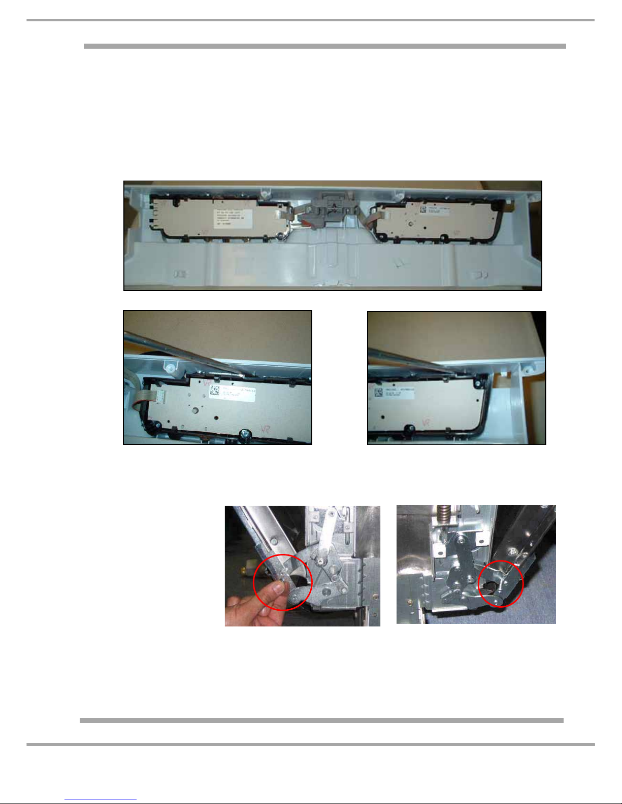
P. Display Board
1. Remove Outer Door panel C)
2. Remove Console Panel (6 screws) and disconnect wiring Harnesses. Noting Connector
orientation and position.
3. Remove the Control Knob
4. Using a flat bladed screw driver, ease clips securing card cradle to console (see Figs. 2 + 3
below.)
1. Remove the front panel and both side panels.
2. Partially open the door
(half way).
Insert a sturdy pin (or
pop rivet etc.) in the
hinge hole (in both left
and right hinges) to
keep the door half
open.
Note 1: IT IS IMPERATIVE THIS IS DONE BEFORE ANY FIXINGS ARE REMOVED.
... continued overleaf
Fig.2
Fig.3
Page 30
30 of 35
Service Manual UK
Indesit Company
English
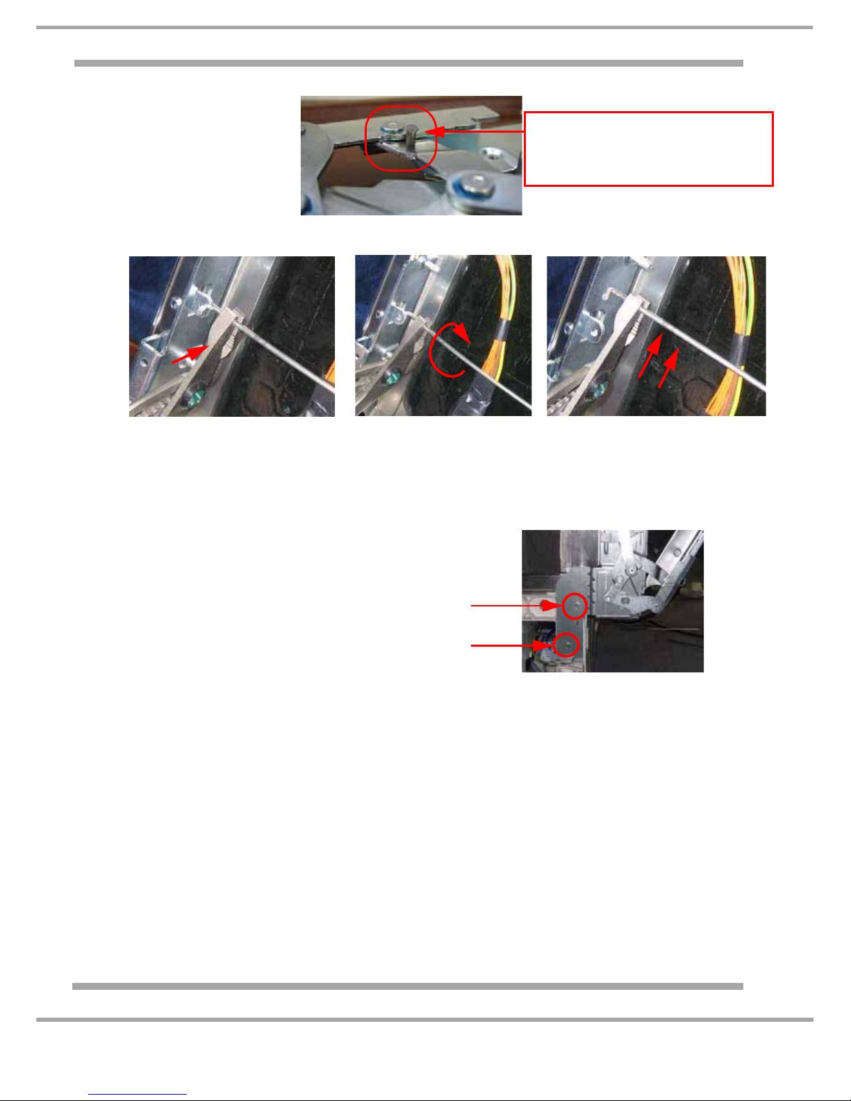
Note 2:
New hinges are supplied
with a Temporary
Locking Pin.
DO NOT REMOVE these
pins until after full
re-assembly.
3. Using pliers take off the tie rod, turning it around its fastening.
4. Disconnect the Earth Tags (Fastons) located on the hinges.
5. Remove 4 screws (2 in each side) fixing the inner door and pull out.
6. Pull the inner door upwards.
7. Remove the screws** located on the inner part of the dishwasher, fixing the hinges to the wash tank.
**Note: One screw each side.
8. Remove 4 screws - 2 per hinge - at
the base of the dishwasher.
9. Fit the new hinges in reverse order. Also refit both Earth Tags and make sure they are secure.
The final action is to remove both Temporary Locking Pins as shown in (2) above.
Each NEW hinge is locked in position
by a temporary pin. DO NOT REMOVE
until BOTH hinges are fixed to the
Door and Dishwasher body.
Remove
2 screws
each side
Page 31

31 of 35
Indesit Company
Service Manual UK English
GENERAL DISHWASHING INFORMATION
NOTE: - Many faults occur over along period of washing incorrectly. Correcting faults may
not immediately cure a problem, e.g. several washes may be necessary to give better
results.
POOR WASH RESULTS
A variety of factors influence wash results and some of the more common are listed below.
A. FOOD OR STARCHY REMAINS LEFT ON CROCKERY
May be detected by running the tip of a fi nger over the surfac e of a dish or by wipi ng with iodine.
This gives a blue/black colour to even the smallest trace of starch. Dried on starch or food soil
should be washed off manually before placing items back into the dishwasher.
1. Food remains not removed prior to washing
Ensure that surplus food is removed and that heavily encrusted or burnt on remains are
pre-soaked.
Ensure that Pre-Wash Programme is used if soiled dishes are being stored in the machine prior
to washing.
2. Spray arm nozzle blockage
Check spray arm and check that the strainer is seated down correctly.
3. Deposits on cups and glasses
Deposits of a sandy like substance etc., in cups and glasses in the upper section of the basket
which looks like resin are generally caused b y the spray arm no t functionin g prop erly.
Possible causes of spray arm inefficiency:
Loading large or tall items in the lower basket which stops the arm revolving.
Upper spray arm split along seam.
Upper spray arm blocked.
Under dosing of powder causing foam and reducing upper spray arm water pressure.
Blocked strainers reducing water to circul ating pump, therefore re ducing upper spray ar m water
pressure.
Low water quantity in machine.
4. Poor arrangement of load or overloading
Ensure that loading allows sufficient force of water to reach all dishes.
In certain cases it may be necessary to leave some spaces empty to ensure good results.
5. Blocked filter or kinked drain hose
Ensure that these items are satisfactory otherwise excess food soil will be present in the
machine.
6. Low wash temperature
Check that correct programme is being used and that the the rmostat is op eratin g at the cor rect
temperature.
7. Insufficient detergent
Food soil may not be completely loosened and will not be kept in suspension in the water.
If in doubt, too much detergent does no harm, but too little in the long run does.
If dishes are heavily soiled add extra deterge nt. Remember - too little detergen t causes foaming.
Page 32

32 of 35
Indesit Company
Service Manual UK English
B. WHITE COATING ON DISHES AND INSIDE THE MACHINE
1. White coating or scale
Detergent not only loosens the remains of food but, together with the calcium salts in the water,
forms water-soluble compounds which prevent the appearance of the white calcium coating or
scale. Insufficient detergent may result in a white coating on dishes and the machine interior.
Unsoftened water can also cause this.
Coatings can often be removed by the following:
Take approximately 100 g of Citric Acid, a white very a cidic powder which ca n be pu rchase d at
chemists. Put the dishes which are to be treated into the dishwasher and fill the dispensing
container with Citric Acid instead of detergent. Then, switch on a normal programme (not the
Economy programme). The container does not take the whole amount of acid powder so
interrupt the programme before the start of the main washing cycle and pour the rest into the
main body of the tub or the inside of the door.
2. White coating on dishes that tastes of salt
Possibly caused by a poor seating regenerati on valve or, most likely by a defective salt cap
gasket.
C. WHITE CLOUDY FILM ON GLASSWARE (THAT CANNOT BE WASHED OFF)
This is probably a surface deposit known as ‘silica scum’ or ‘detergent scum’ which can
sometimes form by precipitation of one of the components of dishwa sher detergents.
The film can be scratched off with the tip of a needle (unlike etching). Unfortunately it can only
be effectively removed under laboratory conditions.
However, the following will prevent or slow down the deposits: -
1. Use less detergent where possible i.e.: when washing medium to lightly soiled items.
2. Do not use poor quality detergent.
3. Make sure that the rinse aid setting is correct. Lack of rinse aid could accentuate the problem.
4. Use a liquid rather than a powder detergent (fo r dish wash ers) pa rt icul arly if glassware is
constantly being washed.
5. Take care not to overload machine.
6. Avoid washing poor quality glassware if possible.
7. Check the salt regeneration setting is correct for the water supply.
8. Check that the machine is filling correctly.
9. Check that the machine is rinsing correctly.
10. Check that the softener by-pass is working correctly.
11. If the dishwasher has programmes of less than 65°C, use these in preference to 65°C
programmes when washing glassware.
D. WHITE DISHES TURNING PINK
1. Caused by a chemical reaction between dishwasher detergent and porcelain. This porcelain is
not dishwasher proof.
2. Formation of silicate scum on the dishes caused by using insufficient detergent.
Silicate scum absorbs iron and/or Manganese which is present in all water supplies. This colours
the scum light brown or pink.
Page 33

33 of 35
Indesit Company
Service Manual UK English
E. POOR DRYING
1. Correct amount of Rinse Aid
The purpose of rinse aid when added to the wate r of a fi na l rins e i s to al low the water to r un off
the dishes as a complete film so that no water-run marks or calcium are left. To enable this to
happen it is essential that the correct amount of rinse aid is dispensed. Too little does not reduce
water tension sufficiently.
Result: The water film breaks up into streaks which make shiny and clear drying impossible.
After all the rest of the water has evaporated, marks are l eft whi ch a re esp ec iall y no tice abl e on
glass and cutlery as well as on items made from stainless steel.
Too much rinse aid leaves smear marks. As a result, the dishes look and feel greasy.
Setting Guide
Set dial to approximately mid positi on. From experience it is advisable to start with too little and
to increase the amount until perfect results are obtained. This can be verified by holding the plate
surface horizontal to incidental light at eye level. An even shine should be observed.
The automatic rinse aid dispenser should then be adjusted accordingly.
2. Opening and closing door during drying
Allows hot air to escape and affects drying efficiency. Notice able if the door is opened
immediately the programme ends.
F. DAMAGED DISHES
Chipping off the edges is not usually due to them rattling against one another during washing.
normally the weight of the dishes is sufficient to withstand the water pressure. Normal daily use
of dishes causes microscopic cracks around the edges which fill with water during washing.
During the heating period the water in these cracks expands and after several temperature
changes the chips may break off. Chipping may on odd occasions be caused by overloading or
by loading tightly together so that they cannot expand during heating.
G. DAMAGED GLASSES
1. Cloudy stains not caused by poor washing or drying, may be due to ring structures in the glass.
These are minute cracks due to stress created during the manufacturing process. Particles may
be washed off by hot water, leaving the surface with an etched and cloudy look. Similar results
occur during hand washing but by using lower wash temperatures and milder detergents the
effect takes longer to show.
2. Etched glassware can also be attributed to 100% softe ned wa ter that i s pr od uce d fr om a water
softening plant that may be installed in the home. In this instance the customer can negotiate
with the manufacturer of the softening plant to install a by-pass system to feed back
approximately 5° of hardness into the water supply, or put the appliance back on to the mains
water supply and use salt as required.
H. CUTLERY TARNISHING / DISCOLOURING
1. Silver cutlery tarnishes when exposed to air. Stainless steel cutlery may show a coating on its
surface after several washes if water has been allowed to evaporate on it, e.g. if incorrect dose
of rinse aid is used. Electrochemical reactions also have an effect and mixing various grades of
stainless, bronze plated and silver cutlery will cause problems.
Page 34

34 of 35
Indesit Company
Service Manual UK English
2. Nickel Silver (German Silver) is an allo y of copper , nickel and zinc, and when subjected to heat
in dishwashing solutions the metal acquires a yellow colour. Maintaining this alloy in attractive
condition requires frequent polishing and it should not be washed in a dishwasher.
3. Pits and rust marks on stainless steel cutlery can usually be attributed to inferior quality stainless
steel or the finished article not being highly polished during manufacture.
Certain food soils have a damaging effect on the protective coating of stainless steel, particularly
foods containing vinegar, fruit and ordinary table salt.
It should be noted that stainless steel should not be left in the humid atmosphere of the
dishwasher for too long after the end of the programme, since this denies the protective coating
the healing effect of oxygen.
4. Bronze or bronze plated cutlery is subject to rapid tarnishing and should not be washed in the
dishwasher.
J. ALUMINIUM COOKING UTENSILS
Bright aluminium utensils may discolour or tarnish due to alkaline attack caused by certain
minerals in the water. Removing these utensils before the final heated rinse should prevent
further problems.
Certain coloured aluminium utensils may discolour and should be washed manually.
K. RUSTING INSIDE THE MACHINE
Normally caused by migration of rust from no n-stainless steel slivers alien to the machine or from
external non-stainless steel nuts used for fixing heater clamps. General surface rusting may
occur along the seams of the tub and c an usually be removed by using a proprietary clea ner like
Solvol Autosol or 3-in-1 Chrome Cleaner.
L. INTERNAL WHITE PLASTIC PARTS OF THE MACHINE TURNING ORANGE OR PINK
Dark red coloured earthenware can sometimes produce this effect by migration of the colouring.
More common, is dishware being loaded with large amounts of tomato ketchup / juice present
or the precipitation of the iron content in the water causing staining because of insufficient
detergent and/or rinse aid dosage. The staining is not harmful but cannot be removed.
M. RAINBOW COLOURING ON STAINLESS STEEL INTERIOR AND COOKING UTENSILS
Usually caused by consistent underdosing of detergent, particularly if liquid detergent is being
used.
N. BLACK MARKS ON CHINA
Usually caused by metal marks from spoons and knives. It can normally be removed by soaking
the china in a mild bleach solution and washing or by gently rubbing with metal polish, wiping dry
then washing.
Page 35

35 of 35
Indesit Company
Service Manual UK English
 Loading...