

Hotpoint ET 6124, ET 7424, ET 6124 X Operating Instructions Manual
Operating Instructions
HOB
Contents
Installation, 2-3
Positioning
Connecting the hob
Disposal
Description of the appliance, 4-5
Control panel
Cooking zone description
Start-up and use, 6
Turning on the hob
Turning off the hob
The booster
The safety devices, 7
Pan recognition
What cookware to use
Acoustic signal
Safety cut out
Overheating protection device
Precautions and tips, 8
Practical advice on using the appliance
General safety
Care and maintenance, 9
Switching the appliance off
Cleaning the appliance
Disassembling the hob
English, 2
GBGB
GBGB
GB
ET 6124
ET 6124 X
ET 7424
GB
All manuals and user guides at all-guides.com
all-guides.com
2
GB
Installation
! Before operating your new appliance please read
this instruction booklet carefully. It contains
important information concerning the safe operation,
installation and maintenance of the appliance.
! Please keep these operating instructions for future
reference. Pass them on to possible new owners of
the appliance.
Positioning
! Keep all packaging materials out of the reach of
children. It may present a choking or suffocation
hazard (see Precautions and tips).
! The appliance must be installed by a qualified
professional in accordance with the instructions
provided. Incorrect installation may damage
property or cause harm to people or animals.
Built-in appliance
Use the appropriate cabinet to ensure that the
appliance functions properly.
The supporting surface must be heat-resistant up
to a temperature of approximately 100°C.
If the appliance is to be installed above an oven,
the oven must have a forced ventilation cooling
system.
Avoid installing the hob above a dishwasher: if
this cannot be avoided, place a waterproof
separation device between the two appliances.
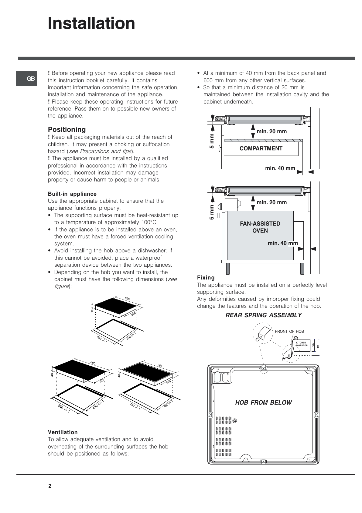
Depending on the hob you want to install, the
cabinet must have the following dimensions (see
figure):
560 +/- 1
490 +/- 1
48
590
520
690
520
560 +/- 1
490 +/- 1
48
785
750 +/- 1
510
490+/- 1
48
Ventilation
To allow adequate ventilation and to avoid
overheating of the surrounding surfaces the hob
should be positioned as follows:
At a minimum of 40 mm from the back panel and
600 mm from any other vertical surfaces.
So that a minimum distance of 20 mm is
maintained between the installation cavity and the
cabinet underneath.
5 mm
min. 20 mm
min. 20 mm
min. 40 mm
COMPARTMENT
5 mm
min. 40 mm
FAN-ASSISTED
OVE N
Fixing
The appliance must be installed on a perfectly level
supporting surface.
Any deformities caused by improper fixing could
change the features and the operation of the hob.
FRONT OF HOB
KITCHEN
WORKTOP
30
40
REAR SPRING ASSEMBLY
HOB FROM BELOW
All manuals and user guides at all-guides.com

GB
3
Connecting the hob
The electrical safety of this appliance can only be
guaranteed if the latter is correctly and efficiently
earthed, in compliance with regulations on electrical
safety. Always ensure that this vital safety measure
has been taken. If you have any doubts, call in a
qualified technician to check the electrical system
thoroughly.
The manufacturer denies all responsibility for damage
resulting from a system which has not been earthed
correctly.
Before powering the appliance, check whether the
technical characteristics featured on the appliance
data plate correspond with those of the mains
electrical system.
Check that the current load of the mains supply and of
the power sockets is suitable for the maximum power
of the appliance, indicated on the appliance data
plate. If in doubt, contact a qualified professional.
Disconnect the appliance from the electricity supply
before all operations.
Connect your hob to the electrical system by means of a
junction box:junction box:
junction box:junction box:
junction box: if the appliance is connected
permanently to the mains, an
omnipolar circuitomnipolar circuit
omnipolar circuitomnipolar circuit
omnipolar circuit
breakerbreaker
breakerbreaker
breaker, accessible if necessary, with a minimum
contact opening of 3 mm should be installed.
Valid only for models with a power supply cable
Some models are supplied with a single-phase power
supply cable, and should consequently only be connected
to the single-phase mains. Observe the wire colours, as
indicated in the diagram attached.
Valid only for models without a power supply cable
Some models are not fitted with a power supply cable,
as the cable should be sized according to the type of
electrical connection in use (see connection table
below). To connect the cable, proceed as follows:
1. Open the terminal
board by inserting a
screwdriver into the
side tabs of the cover.
Use the screwdriver as
a lever by pushing it
down to open the cover
(see diagram).
2. Loosen the cable
clamp screw and remove
it, using a screwdriver as
a lever (see figure).
3. Remove the wire
contact screws L-N-
,
then fasten the wires
under the screw heads,
respecting the colour
code: Black/Blue (N),
Red/Brown (L) and Bare
Wire/Yellow-Green ( ).
Position the power supply cable wires according to
the indications in the table.
Once the connections have been made, tighten all
the terminal screws fully.
Fasten the supply cable in place with the clamp and
close the cover of the terminal board.
! If the hob is fitted above a built-in oven, the hob and the
oven must be connected to the mains separately for safety
reasons and to simplify operations when it is necessary to
pull the oven out for some reason.
This appliance conforms to the
following European Economic
Community directives:
- 73/23/EEC dated 19/02/73 (Low Voltage) and subsequent
amendments;
- 89/336/EEC dated 03/05/89 (Electromagnetic
Compatibility) and subsequent amendments;
- 93/68/EEC dated 22/07/93 and subsequent amendments.
Disposal
When disposing of packaging material: observe local
legislation so that the packaging may be reused.
The European Directive 2002/96/EC relating to Waste
Electrical and Electronic Equipment (WEEE) states that
household appliances should not be disposed of using
the normal solid urban waste cycle. Exhausted
appliances should be collected separately in order to
optimise the cost of re-using and recycling the materials
inside the machine, while preventing potential damage
to the atmosphere and to public health. The crossed-out
dustbin is marked on all products to remind the owner of
their obligations regarding separated waste collection.
For further information relating to the correct disposal of
exhausted household appliances, owners may contact
the public service provided or their local dealer.
Electrical
connections
Voltage, Frequency
Fuses,
Sections
GB 220-240V
-1+N~50 Hz
25 A*
2,5 mm²
* Application of the simultaneity coefficient in
accordance with cei 60335-2-6 norm
N
L
All manuals and user guides at all-guides.com
4
GB
Description
of the appliance
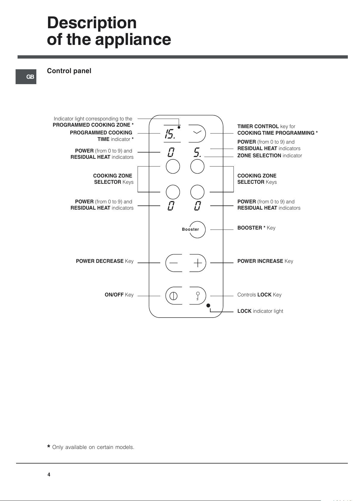
Control panel
*
Only available on certain models.
Booster
15.
0
00
5.
ON/OFF Key
POWER DECREASE Key
COOKING ZONE
SELECTOR Keys
COOKING ZONE
SELECTOR Keys
TIMER CONTROL key for
COOKING TIME PROGRAMMING *
ZONE SELECTION indicator
Controls LOCK Key
LOCK indicator light
Indicator light corresponding to the
PROGRAMMED COOKING ZONE *
POWER INCREASE Key
BOOSTER * Key
POWER (from 0 to 9) and
RESIDUAL HEAT indicators
POWER (from 0 to 9) and
RESIDUAL HEAT indicators
POWER (from 0 to 9) and
RESIDUAL HEAT indicators
POWER (from 0 to 9) and
RESIDUAL HEAT indicators
PROGRAMMED COOKING
TIME indicator *
All manuals and user guides at all-guides.com
 Loading...