


Please phone us on
08448 24 24 24
to activate your
guarantee
EG 902 GX S
English
Operating Instructions
DUAL FUEL COOKER
Contents
Operating Instructions,1
Warnings,2
Description of the appliance,3
Installation,4
Start-up and use,8
Timer (Electric oven),11
Troubleshooting,12
Precautions and tips,15
Maintenance and care,15
After Sales Service,17
Guarantee,18

PLEASE PHONE US TO REGISTER YOUR APPLIANCE AND ACTIVATE YOUR PARTS GUARANTEE ON 08448 24 24 24
Warnings
GB
WARNING: The appliance and its
accessible parts become hot during use.
Care should be taken to avoid touching
heating elements. Children less than 8
years of age shall be kept away unless
continuously supervised. This appliance
can be used by children aged from 8 years
and above and persons with reduced
physical, sensory or mental capabilities
or lack of experience and knowledge
if they have been given supervision
or instruction concerning use of the
appliance in a safe way and understand
the hazards involved. Children shall not
play with the appliance. Cleaning and
user maintenance shall not be made by
children without supervision.
WARNING: Ensure that the appliance is
switched off before replacing the lamp to
avoid the possibility of electric shock.
CAUTION: the use of inappropriate hob
guards can cause accidents.
WARNING: Unattended cooking on a hob
with fat or oil can be dangerous and may
result in re.
NEVER try to extinguish a re with water,
but switch off the appliance and then
cover ame e.g. with a lid or a re blanket.
Do not use harsh abrasive cleaners or
sharp metal scrapers to clean the oven
door glass since they can scratch the
surface, which may result in shattering
of the glass.
The internal surfaces of the compartment
(where present) may become hot.
Never use steam cleaners or pressure
cleaners on the appliance.
“Remove any liquid from the lid before
opening it.
Do not close the glass cover (if present)
when the gas burners or electric hotplates
are still hot.”
2
PLEASE PHONE US TO REGISTER YOUR APPLIANCE AND ACTIVATE YOUR PARTS GUARANTEE ON 08448 24 24 24
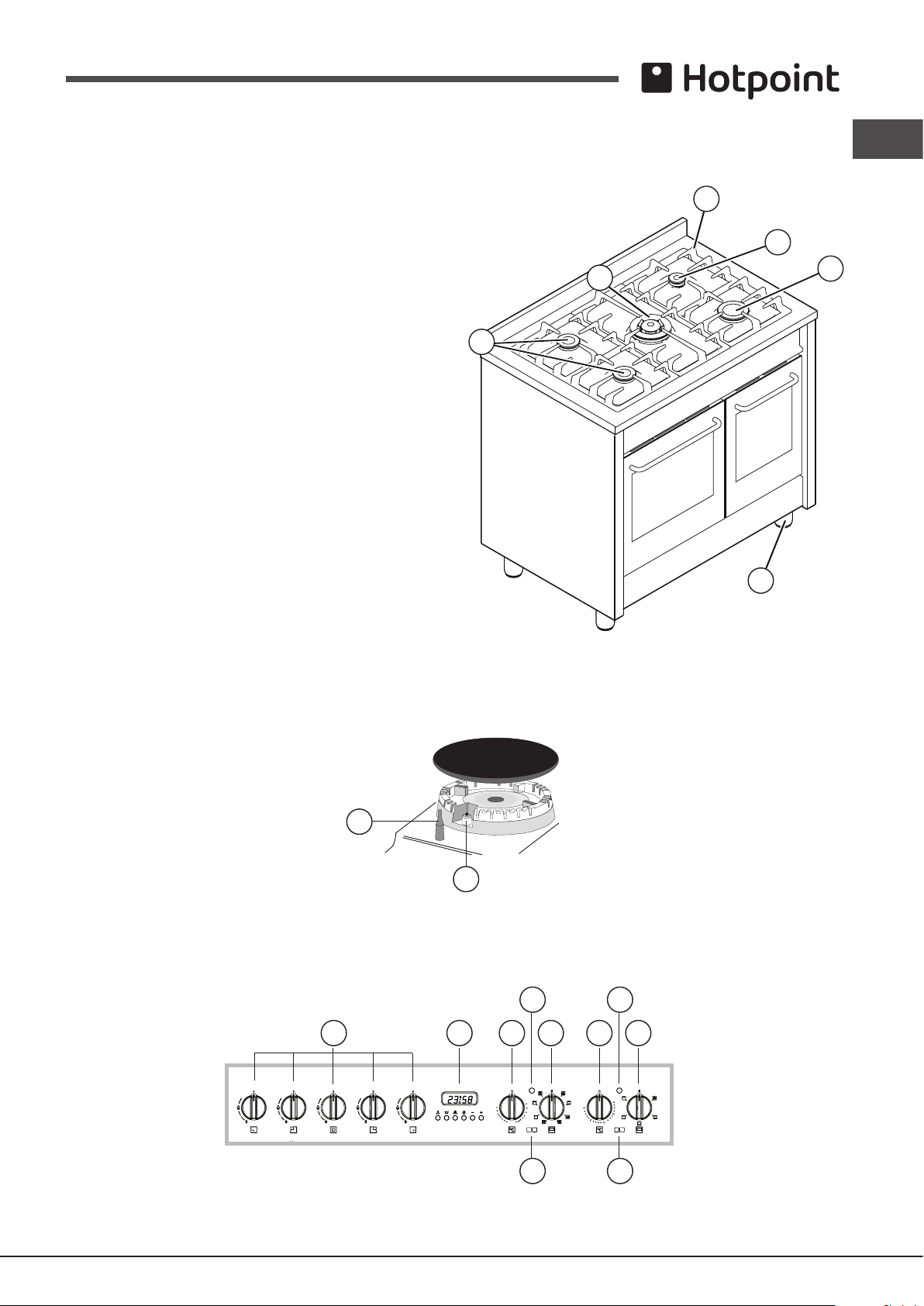
Description of the appliance
Overall view
GB
1 AUXLIARY gas burner
2 SEMI-RAPID gas burner
3 RAPID gas burner
4 TRIPLE RING gas burner
5 PAN SUPPORT FOR COOKWARE
6 ADJUSTABLE FEET or LEGS
7 SAFETY DEVICE - Activates if the ame accidentally
goes out (spills, drafts, etc.), interrupting the supply of
gas to the burner.
8 IGNITOR for Gas BURNERS
Control panel
9 GAS BURNERS Control knobs
10 TIMER
11 THERMOSTAT knob (1
12 THERMOSTAT Indicator light (1
13 SELECTOR knob (1
14 THERMOSTAT knob (
15 THERMOSTAT Indicator light (
16 SELECTOR knob (
2ND.
17 (
OVEN)
1ST.
18 (
OVEN)
ST.
2ND.
ST.
OVEN)
OVEN)
2ND.
OVEN)
OVEN)
ST.
2ND.
OVEN)
OVEN)
5
1
4
3
2
6
7
8
12
15
9 10 11 1413 16
50
MAX
200
100
150
18
50
MAX
100
200
150
17
3
PLEASE PHONE US TO REGISTER YOUR APPLIANCE AND ACTIVATE YOUR PARTS GUARANTEE ON 08448 24 24 24
Installation
GB
! Before placing your new appliance into operation please
read these operating instructions carefully. It contains
important information concerning the safe installation and
operation of the appliance.
! Please keep these operating instructions for future
reference. Make sure that the instructions are kept with the
appliance if it is sold, given away or moved.
! The appliance must be installed by a qualied professional
in accordance with the instructions provided.
! Any necessary adjustment or maintenance must be
performed after the cooker has been disconnected from
the electricity supply.
The cookers have the following technical specications:
Category: II 2H3+
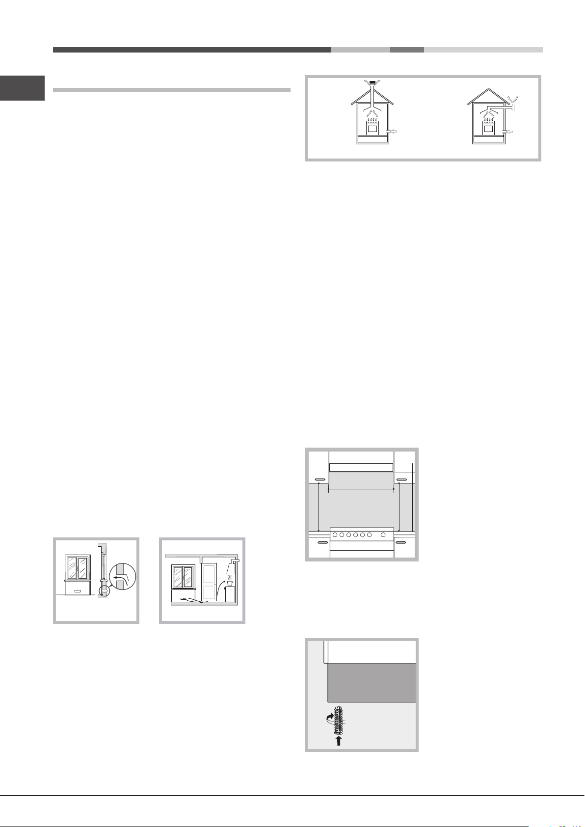
Room ventilation
The appliance may only be installed in permanentlyventilated rooms, according to current national legislation.
The room in which the appliance is installed must be
ventilated adequately in order to provide as much air as is
needed by the normal gas combustion process (the ow of
air must not be lower than 2 m3/h per kW of installed power).
The air inlets, protected by grilles, should have a duct
with an inner cross section of at least 100 cm2 and should
be positioned so that they are not liable to even partial
obstruction (see gure A).
These inlets should be enlarged by 100% - with a minimum
of 200 cm2 - whenever the surface of the hob is not equipped
with a ame failure safety device. When the ow of air is
provided in an indirect manner from adjacent rooms (see
gure B), provided that these are not communal parts of a
building, areas with increased re hazards or bedrooms, the
inlets should be tted with a ventilation duct leading outside
as described above.
Adjacent
Room
Room to be
Vented
In a chimney stack or branched flue.
(exclusively for cooking appliances)
Directly to
the Outside
! The liqueed petroleum gases are heavier than air and
collect by the oor, therefore all rooms containing LPG
cylinders must have openings leading outside so that any
leaked gas can escape easily.
LPG cylinders, therefore, whether partially or completely full,
must not be installed or stored in rooms or storage areas which
are below ground level (cellars, etc.). Only the cylinder being
used should be stored in the room; this should also be kept well
away from sources of heat (ovens, chimneys, stoves) which
may cause the temperature of the cylinder to rise above 50°C.
Positioning and levelling
! The appliance may be installed alongside any cupboards
whose height does not exceed that of the hob surface.
! Make sure that the wall in contact with the back of the
appliance is made from a non-ammable, heat-resistant
material (T 90°C).
To install the appliance correctly:
• Place it in the kitchen, the dining room or the studio at
(not in the bathroom).
• If the top of the hob is higher than the cupboards, the
appliance must be installed at least 500 mm away from them.
• If the cooker is installed
underneath a wall cabinet,
there must be a minimum
distance of 420 mm between
this cabinet and the top of
the hob.
This distance should be
700 mm. without hood
min. 650 mm. with hood
min.
increased to 700 mm if the
wall cabinets are ammable
(see gure).
mm.
420
Min.
HOOD
Min. mm.
600
420
Min. mm.
• Do not position blinds behind the cooker or less than 200
A
Examples of
ventilation holes
for comburant air.
Enlarging the ventilation slot
between window and floor.
A B
! After prolonged use of the appliance, it is advisable to open
a window or increase the speed of any fans used.
mm away from its sides.
• Any hoods must be installed in accordance with the
instructions listed in the relevant operating manual.
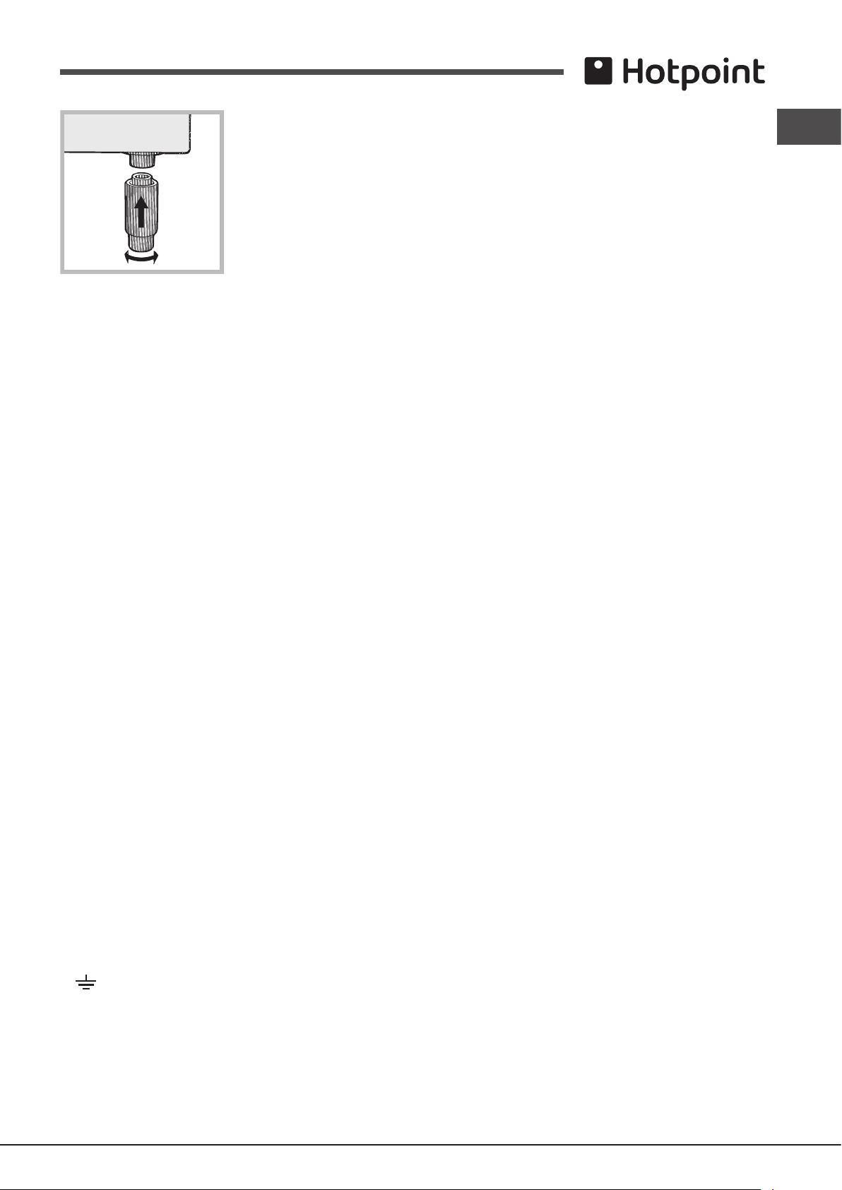
Levelling
If it is necessary to level the
appliance, screw the
adjustable feet into the
Disposing of combustion fumes
The efcient disposal of combustion fumes should be
guaranteed using a hood which is connected to a safe
places provided on each
corner of the base of the
cooker (see gure).
and efcient natural suction chimney, or using an electric
fan which begins to operate automatically every time the
appliance is switched on (see gure).
4
PLEASE PHONE US TO REGISTER YOUR APPLIANCE AND ACTIVATE YOUR PARTS GUARANTEE ON 08448 24 24 24
Electrical connection
The legs* t into the slots on
the underside of the base of
the cooker.
Replacing the cable
Use a rubber cable of the type H05VV-F with a cross section
of 3 x 2.5 mm². The yellow-green earth wire must be 2 ÷ 3
cm longer than the other wires.
Gas connection
Connection to the gas network or to the gas cylinder may be
carried out using a exible rubber or steel hose, in accordance
with current national legislation and after making sure that the
appliance is suited to the type of gas with which it will be supplied
(see the rating sticker on the cover: if this is not the case see
below). When using liquid gas from a cylinder, install a pressure
regulator which complies with current national regulations.
GB
WARNING – THIS APPLIANCE MUST BE EARTHED.
The appliance is designed to work with alternating current
at the supply voltage and frequency indicated on the rating
plate (situated on the rear part of the appliance and on the
last page of the instruction booklet) or at the end of the
instruction booklet. Make sure that the local supply voltage
corresponds to the voltage indicated on the rating plate.
To connect directly to the mains supply, a double-pole switch
with a contact separation of at least 3 mm suitable for the
load and complying with current standards and regulations,
must be tted between the appliance and the mains supply
outlet. The yellow-green earth wire must not be interrupted
by the switch. The supply cable must be in such a position
that no part of it can reach a temperature of 50 °C above
room temperature. Do not use adapters or shunts as they
could cause heating or burning.
Before connecting to the power supply, make sure that:
• the limiter valve and the domestic system can withstand
the load from the appliance (see rating plate);
• the supply system is efciently earthed according to
standards and laws in force;
• the socket or double-pole switch are easily accessible
when the appliance is installed.
FAILURE TO OBSERVE THE ACCIDENT-PREVENTION
REGULATIONS RELIEVES THE MANUFACTURER OF
ALL LIABILITY.
Important: the wires in the mains lead are coloured in
accordance with the following code:
! Make sure that the gas supply pressure is consistent
with the values indicated in the Table of burner and nozzle
specifications (see below). This will ensure the safe
operation and durability of your appliance while maintaining
efcient energy consumption.
Gas connection using a exible rubber hose
Make sure that the hose complies with current national
legislation. The internal diameter of the hose must measure:
8 mm for a liquid gas supply;
13 mm for a methane gas supply.
Once the connection has been performed, make sure that
the hose:
• Does not come into contact with any parts which reach
temperatures of over 50°C.
• Is not subject to any pulling or twisting forces and that it
is not kinked or bent.
• Does not come into contact with blades, sharp corners
or moving parts and that it is not compressed.
• Is easy to inspect along its whole length so that its
condition may be checked.
• Is shorter than 1500 mm.
• Fits rmly into place at both ends, where it will be xed
using clamps which comply with current regulations.
! Once the appliance has been installed, the power supply
cable and the electrical socket must be easily accessible.
! The cable must not be bent or compressed.
Green & Yellow - Earth
Blue - Neutral
Brown - Live
As the colours of the wires in the mains lead may not
correspond with the coloured markings identifying the
terminals in your plug, proceed as follows:
Connect the Green & Yellow wire to terminal marked “E”
or or coloured Green or Green & Yellow.
Connect the Brown wire to the terminal marked “L” or
coloured Red.
Connect the Blue wire to the terminal marked “N” or
coloured Black.
! The cable must be checked regularly and replaced by
authorised technicians only (see Assistance).
! The manufacturer declines any liability should these
safety measures not be observed.
! If one or more of these conditions is not fullled or if the
cooker must be installed according to the conditions listed
for class 2 - subclass 1 appliances (installed between two
cupboards), the exible steel hose must be used instead
(see below).
Connecting a exible jointless stainless steel pipe to
a threaded attachment
* Only available on certain models.
5
PLEASE PHONE US TO REGISTER YOUR APPLIANCE AND ACTIVATE YOUR PARTS GUARANTEE ON 08448 24 24 24
Make sure that the hose and gaskets comply with current
GB
national legislation.
To begin using the hose, remove the hose holder on
the appliance (the gas supply inlet on the appliance is a
cylindrical threaded 1/2 gas male attachment).
! Should the gas pressure used be different (or vary slightly)
from the recommended pressure, a suitable pressure
regulator must be tted to the inlet hose in accordance
with current national regulations relating to “regulators for
channelled gas”.
! Perform the connection in such a way that the hose length
does not exceed a maximum of 2 metres, making sure that
the hose is not compressed and does not come into contact
with moving parts.
Checking the connection for leaks
When the installation process is complete, check the hose
ttings for leaks using a soapy solution. Never use a ame.
Adapting to different types of gas
It is possible to adapt the appliance to a type of gas other
than the default type (this is indicated on the rating label
on the cover).
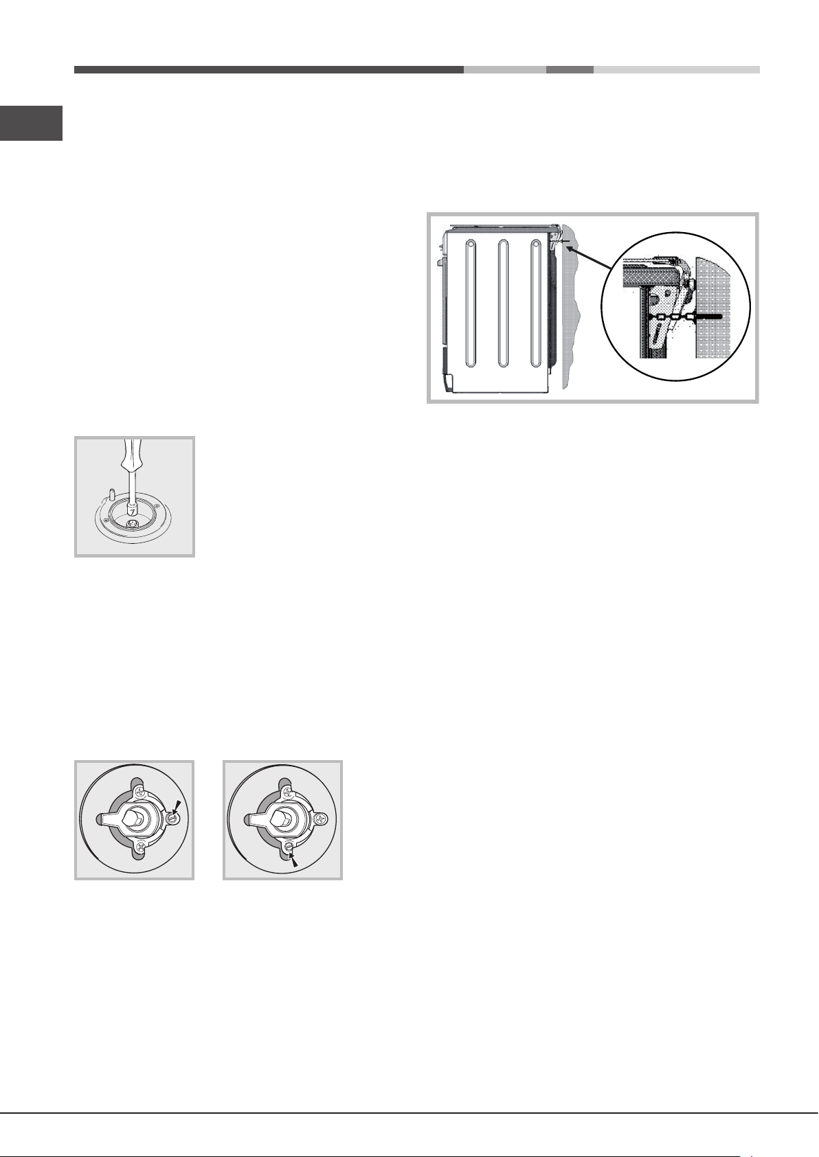
Adapting the hob
Replacing the nozzles for the hob
burners:
1. Remove the hob grids and slide
the burners off their seats.
2. Unscrew the nozzles using a 7
mm socket spanner (see gure),
and replace them with nozzles
suited to the new type of gas (see
Burner and nozzle specications
table).
3. Replace all the components by following the above
instructions in reverse.
Safety Chain
! In order to prevent accidental tipping of the appliance,
for example by a child climbing onto the oven door, the
supplied safety chain MUST be installed!
The cooker is tted with a safety chain to be xed by means
of a screw (not supplied with the cooker) to the wall behind
the appliance, at the same height as the chain is attached
to the appliance.
Choose the screw and the screw anchor according to the
type of material of the wall behind the appliance. If the head
of the screw has a diameter smaller than 9mm, a washer
should be used. Concrete wall requires the screw of at least
8mm of diameter, and 60mm of length.
Adjusting the hob burners’ minimum setting:
1. Turn the tap to the minimum position.
2. Remove the knob and adjust the regulatory screw, which
is positioned inside or next to the tap pin, until the ame is
small but steady.
! If the appliance is connected to a liquid gas supply, the
regulatory screw must be fastened as tightly as possible.
3. While the burner is alight, quickly change the position of
the knob from minimum to maximum and vice versa several
times, checking that the ame is not extinguished.
! The hob burners do not require primary air adjustment.
! After adjusting the appliance so it may be used with a
different type of gas, replace the old rating label with a
new one which corresponds to the new type of gas (these
labels are available from Authorised Technical Assistance
Centres).
6

PLEASE PHONE US TO REGISTER YOUR APPLIANCE AND ACTIVATE YOUR PARTS GUARANTEE ON 08448 24 24 24
Table of burner and nozzle specications
Table 1 Liquid Gas Natural Gas
GB
Burner Diameter
(mm)
Thermal Power
kW (p.c.s.*)
Nominal Reduced
Fast
(Large) (R)
Semi Fast
(Medium) (S)
Auxiliary
(Small) (A)
Triple Ring
(TC)
Supply
pressures
100
75
55
130
3.00
1.65
1.00
3.25
Nominal (mbar)
Minimum (mbar)
Maximum (mbar)
* At 15°C and 1013 mbar - dry gas
Propane P.C.S. = 50.37 MJ/Kg
Butane P.C.S. = 49.47 MJ/Kg
Methane P.C.S. = 37.78 MJ/m
0.70
0.40
0.40
1.30
3
By-pass
1/100
(mm)
40
30
30
57
Nozzle
1/100
(mm)
86
64
50
91
***
218
120
73
236
28-30
20
35
Flow*
g/h
**
214
118
71
232
37
25
45
Nozzle
1/100
(mm)
116
96
71
124
Flow*
l/h
286
157
95
309
20
17
25
TECHNICAL DATA (1st Oven)
Oven
dimensions
HxLxP
Volume
Voltage and
frequency
Burners
ENERGY
LABEL
33,8 x 40,2 x 41,0 cm
lt. 56
see data plate
may be adapted for use with any type
of gas shown on the data plate.
Directive 2002/40/EC on the label of
electric ovens. Standard EN 50304-60350
Energy consumption for Natural
convection – heating mode:
Traditional mode
Declared energy consumption for Forced
convection Class – heating mode:
Fan assisted.
This appliance conforms to the following
European Economic Community
directives:
- 2006/95/EEC dated 12/12/06 (Low
Voltage) and subsequent amendments
- 2004/108/EEC dated 15/12/04
(Electromagnetic Compatibility) and
subsequent amendments
- 93/68/EEC dated 22/07/93 and
subsequent amendments.
- 2009/142/EEC dated 30/11/09 (Gas)
and subsequent amendments.
- 2002/96/EC and subsequent
amendments.
TECHNICAL DATA (2nd Oven)
Oven
dimensions
HxLxP
Volume
Voltage and
frequency
Burners
ENERGY
LABEL
33,1 x 28,8 x 43,9 cm
lt. 42
see data plate
may be adapted for use with any type
of gas shown on the data plate.
Directive 2002/40/EC on the label of
electric ovens. Standard EN 50304-60350
Energy consumption for Natural
convection – heating mode:
Traditional mode
This appliance conforms to the following
European Economic Community
directives:
- 2006/95/EEC dated 12/12/06 (Low
Voltage) and subsequent amendments
- 2004/108/EEC dated 15/12/04
(Electromagnetic Compatibility) and
subsequent amendments
- 93/68/EEC dated 22/07/93 and
subsequent amendments.
- 2009/142/EEC dated 30/11/09 (Gas)
and subsequent amendments.
- 2002/96/EC and subsequent
amendments.
7

PLEASE PHONE US TO REGISTER YOUR APPLIANCE AND ACTIVATE YOUR PARTS GUARANTEE ON 08448 24 24 24
Start-up and use
GB
Using the hob
Lighting the burners
For each BURNER knob there is a complete ring showing
the strength of the ame for the relevant burner.
To light one of the burners on the hob:
1. Bring a ame or gas lighter close to the burner.
2. Press the BURNER knob and turn it in an anticlockwise
direction so that it is pointing to the maximum ame setting .
3. Adjust the intensity of the ame to the desired level by
turning the BURNER knob in an anticlockwise direction.
This may be the minimum setting , the maximum setting
or any position in between the two.
The appliance is fitted with an
electronic lighting device (see
gure), press the BURNER knob
and turn it in an anticlockwise
direction, towards the minimum
ame setting, until the burner is lit.
The burner might be extinguished
when the knob is released. If this
occurs, repeat the process, holding
the knob down for a longer period of time.
! If the ame is accidentally extinguished, switch off the burner
and wait for at least 1 minute before attempting to relight it.
The appliance is equipped with a ame failure safety device,
press and hold the BURNER knob for approximately 6
seconds to keep the ame alight and to activate the device.
To switch the burner off, turn the knob until it reaches the
stop position ●.
For the best performance of your burners, keep the following
in mind: All types of pans can be used on the burners. The
important thing is that the bottom should be completely even.
Using the oven
! When inserting the shelf
make sure the backstop is
at the rear of the cavity (see
image).
! Before operating the product, remove all plastic lm from
the sides of the appliance.
! The rst time you use your appliance, heat the empty
oven with its door closed at its maximum temperature for
at least half an hour. Ensure that the room is well ventilated
before switching the oven off and opening the oven door.
The appliance may emit a slightly unpleasant odour caused
by protective substances used during the manufacturing
process burning away.
In order to cool down the temperature of their exterior, some
models are tted with a cooling fan that comes on when the
programme selector knob is turned. In this case, the fan
is always on and a normal ow of air can be heard exiting
between the oven door and the control panel.
Note: when cooking is done, the fan stays on, even if knob
is set to “0”, until the oven has cooled down sufciently.
Practical advice on using the burners
For the burners to work in the most efcient way possible and
to save on the amount of gas consumed, it is recommended
that only pans which have a lid and a at base are used.
They should also be suited to the size of the burner.
Burner
Fast (R)
Semi Fast (S)
Auxiliary (A)
Triple Crown (TC)
The hob is tted with a reducing pan stand (shown gure)
which should only be used on the auxiliary burner ‘A’.
Ø Cookware Diameter (cm)
24 - 26
16 - 22
10 - 14
24 - 26
In “Fast cooking” mode, the fan comes on automatically
only when the oven is hot.
Once you have removed the food from the oven, we
recommend you leave the oven door ajar for a few minutes:
this will drastically reduce the duration of the cooling cycle.
The process is controlled by an additional thermostat and
can consist of one or more cycles.
1. Select the desired cooking mode by turning the
SELECTOR knob .
2. Select the recommended temperature for the cooking mode
or the desired temperature by turning the THERMOSTAT
knob .
A list detailing cooking modes and suggested cooking
temperatures can be found in the relevant table (see Oven
cooking advice table).
8

PLEASE PHONE US TO REGISTER YOUR APPLIANCE AND ACTIVATE YOUR PARTS GUARANTEE ON 08448 24 24 24
During cooking it is always possible to:
• Change the cooking mode by turning the SELECTOR
knob .
• Change the temperature by turning the THERMOSTAT
knob .
• Stop cooking by turning the SELECTOR knob to the
“0” position.
PIZZA mode
The circular heating elements and the elements at the
bottom of the oven are switched on and the fan is activated.
This combination heats the oven rapidly by producing a
considerable amount of heat, particularly from the element
at the bottom. If you use more than one rack at a time,
switch the position of the dishes halfway through the cooking
process.
GB
! Always place cookware on the rack(s) provided.
THERMOSTAT indicator light
When this is illuminated, the oven is generating heat. It
switches off when the inside of the oven reaches the selected
temperature. At this point the light illuminates and switches
off alternately, indicating that the thermostat is working and
is maintaining the temperature at a constant level.
OPERATION indicator light
When this is illuminated, the oven is generating heat.
Cooking modes for Multi-function
main oven (1 rst Oven)
! The rst time you use your appliance, heat the empty
oven with its door closed at its maximum temperature for
at least half an hour. Ensure that the room is well ventilated
before switching the oven off and opening the oven door.
The appliance may emit a slightly unpleasant odour caused
by protective substances used during the manufacturing
process burning away.
! A temperature value can be set for all cooking modes
between 50°C and Max, except for the following modes
• MAXI-GRILL / MINI-GRILL (recommended: set only to
MAX power level)
• GRATIN (recommended: do not exceed 200°C).
Oven light
This is switched on by turning the SELECTOR knob
to any position other than “0”. It remains lit as long as the
oven is operating.
MULTI-COOKING mode
All the heating elements (top, bottom and circular) switch
on and the fan begins to operate. Since the heat remains
constant throughout the oven, the air cooks and browns
food in a uniform manner. A maximum of two racks may be
used at the same time.
MINI-GRILL mode
The central part of the top heating element is switched on.
The high and direct temperature of the grill is recommended
for food that requires a high surface temperature (veal and
beef steaks, llet steak and entrecôte). This cooking mode
uses a limited amount of energy and is ideal for grilling small
dishes. Place the food in the centre of the rack, as it will not
be cooked properly if it is placed in the corners.
MAXI-GRILL mode
All the top heating element are activated .
GRATIN mode
The top heating element and the rotisserie (where
present) are activated and the fan begins to operate. This
combination of features increases the effectiveness of the
unidirectional thermal radiation provided by the heating
elements through forced circulation of the air throughout the
oven. This helps prevent food from burning on the surface
and allows the heat to penetrate right into the food.
! The GRILL and GRATIN cooking modes must be
performed with the oven door shut.
Practical cooking advice
By selecting with the knob, the light is switched on
without any of the heating elements being activated.
TRADITIONAL OVEN mode
Both the top and bottom heating elements will come on.
When using this traditional cooking mode, it is best to use
one cooking rack only. If more than one rack is used, the
heat will be distributed in an uneven manner.
BAKING mode
The rear heating element and the fan are switched on,
thus guaranteeing the distribution of heat in a delicate and
uniform manner throughout the entire oven. This mode is
ideal for baking and cooking temperature sensitive foods
(such as cakes that need to rise) and for the preparation of
pastries on 3 shelves simultaneously.
! Do not place racks in position 1 or 5 during fan-assisted
cooking. Excessive direct heat can burn temperature
sensitive foods.
MULTILEVEL
• Use positions 2 and 4, placing the food that requires more
heat on the rack in position 2.
• Place the dripping pan on the bottom and the rack on top.
GRILL
• When using the GRILL cooking mode, place the rack in
position 2 or 3 and the dripping pan in position 1 to collect
cooking residues (fat and/or grease). When using the
GRATIN cooking mode, place the rack in position 2 or 3 and
the dripping pan in position 1 to collect cooking residues.
9

PLEASE PHONE US TO REGISTER YOUR APPLIANCE AND ACTIVATE YOUR PARTS GUARANTEE ON 08448 24 24 24
• We recommend that the power level is set to maximum.
GB
The top heating element is regulated by a thermostat
and may not always operate constantly.
PIZZA MODE
• Use a light aluminium pizza pan. Place it on the rack
provided.
For a crispy crust, do not use the dripping pan as it
prevents the crust from forming by extending the total
cooking time.
• If the pizza has a lot of toppings, we recommend adding
the mozzarella cheese on top of the pizza halfway
through the cooking process.
THERMOSTAT indicator light
When this is illuminated, the oven is generating heat. It
switches off when the inside of the oven reaches the selected
temperature. At this point the light illuminates and switches
off alternately, indicating that the thermostat is working and
is maintaining the temperature at a constant level.
Oven light
This is switched on by turning the SELECTOR knob
to any position other than “0”. It remains lit as long as the
oven is operating. By selecting with the knob, the light
is switched on without any of the heating elements being
activated.
Cooking modes for Conventional
main oven (2nd oven)
! The rst time you use your appliance, heat the empty
oven with its door closed at its maximum temperature for
at least half an hour. Ensure that the room is well ventilated
before switching the oven off and opening the oven door.
The appliance may emit a slightly unpleasant odour caused
by protective substances used during the manufacturing
process burning away.
! A temperature value can be set for all cooking modes
between 50°C and Max, except for the following modes
• MAXI-GRILL / MINI-GRILL (recommended: set only to
MAX power level)
Starting the oven
1. Select the desired cooking mode by turning the
SELECTOR knob .
2. Select the recommended temperature for the cooking mode
or the desired temperature by turning the THERMOSTAT
knob .
A list detailing cooking modes and suggested cooking
temperatures can be found in the relevant table (see Oven
cooking advice table).
TRADITIONAL OVEN mode
Both the top and bottom heating elements will come on.
When using this traditional cooking mode, it is best to use
one cooking rack only. If more than one rack is used, the
heat will be distributed in an uneven manner.
PASTRY Mode
The bottom heating element comes on.
This mode is ideal for baking and cooking delicate foods especially cakes that need to rise because the heat coming
from the bottom helps the leavening process.
Please note that it takes a considerable amount of time
for the higher temperatures to be reached, therefore we
recommend you use the “Convection Mode” in these cases.
MINI GRILL
The top central heating element comes on.
The extremely high and direct temperature of the grill
makes it possible to brown the surface of meats and roasts
while locking in the juices to keep them tender. The grill is
also highly recommended for dishes that require a high
temperature on the surface: beef steaks, veal, rib steak,
lets, hamburgers etc...
Some grilling examples are included in the “Practical
Cooking Advice” paragraph.
During cooking it is always possible to:
• Change the cooking mode by turning the SELECTOR
knob .
• Change the temperature by turning the THERMOSTAT
knob .
• Set the total cooking time and the cooking end time (see
below).
• Stop cooking by turning the SELECTOR knob to the
“0” position.
! Never put objects directly on the bottom of the oven; this
will avoid the enamel coating being damaged. Only use
position 1 in the oven when cooking with the rotisserie spit.
! Always place cookware on the rack(s) provided.
10
MAXI GRILL
The top heating element comes on.
This mode can be used to brown food at the end of cooking.
Practical cooking advice
GRILL
• When using the GRILL cooking mode, place the rack in
position 2 or 3 and the dripping pan in position 1 to collect
cooking residues (fat and/or grease).
• We recommend that the power level is set to maximum.
The top heating element is regulated by a thermostat
and may not always operate constantly.
! The GRILL cooking mode must be performed with the
oven door shut.

PLEASE PHONE US TO REGISTER YOUR APPLIANCE AND ACTIVATE YOUR PARTS GUARANTEE ON 08448 24 24 24
Timer (Electric oven)
The programmer makes it possible to preset the oven and
the grill in terms of:
• delay start with a preset length of time for cooking;
• immediate start with a preset length of time for cooking;
• timer.
Button functions:
: Timer with hour and minutes;
: Length of cooking time;
: End cooking time;
: Manual change;
: Change time (backwards);
: Change time (forwards).
How to Reset the Digital Clock
After the appliance has been connected to the power source
or following a power outage, the clock display will begin to
blink and read: 0:00
• Press the buttons at the same time. Then use
(within 4 seconds) the and buttons to set the exact
time.
Use the button to move the time forwards.
Use the button to move the time backwards.
The time can also be changed in the following two ways:
1. Repeat all of the foregoing steps.
2. Press the button, and then use the and buttons
to reset the time.
Manual Operation Mode for the Oven
After the time has been set, the programmer is automatically
set to manual mode.
Note: Press the button to return the oven to manual
mode after every “Automatic” cooking session.
Delayed Start Time with Preset Cooking Length
The length and the end cooking times must be set. Let us
suppose that the display shows 10:00.
1. Turn the oven control knob to the cooking setting and
temperature desired (example: convection oven at 200°C).
2. Press the and the use (within 4 seconds) the and
buttons to set the length of the cooking time. Let us
suppose that 30 minutes was set for the length of the
cooking time. In this case, the display will show:
When “auto” is lighted, it indicates that the length and end
cooking time have been preset to operate in automatic
mode. At this point, the oven will turn on automatically
at 12:30 in order to nish the cooking session within 30
minutes. When the oven is on, the symbol (cooking
pot) will appear on the display for the entire length of the
cooking process. The button can be pressed at any
time to display the setting for the length of the cooking
time, while the button can be pressed to display the
end cooking time.
At the end of the cooking time, an acoustic signal will
sound. Press any button it turn it off (except the and
buttons).
Immediate Start Time with Preset Cooking Length
When only the length of the cooking time is set (points 1 and
2 of the paragraph entitled, “Delayed Start Time with Preset
Cooking Length”), the cooking session starts immediately.
Cancelling a Preset Cooking Time
Press the button, and use the button to set the time to:
Then press the manual cooking mode button .
Timer Feature
The timer can be used to count down from a given length
of time. This feature does not control when the oven comes
on or turns off, but, rather, it only emits an acoustic signal
when the preset time has run out.
Press the button, and the display will read:
Then use the and buttons to set the desired time.
Release the button, and the timer will start at that second.
The display will show the current time.
At the end of the preset time, an acoustic signal will sound,
which can be turned off by pressing any button (except the
and buttons), and the symbol will turn off.
GB
Changing and Cancelling Settings
• The settings can be changed at any time by pressing the
Release the button, and within 4 seconds, the current time
will reappear with the symbol and “auto.”
3. Press the button, and then use the and buttons
to set the end cooking time. Let us suppose that it is 13:00
4. Release the button and the display will show the current
time within 4 seconds:
corresponding button and using the or button.
• When the length setting for the cooking time is cancelled,
the end cooking time setting is also cancelled, and vice
versa.
• When in automatic cooking mode, the appliance will not
accept end cooking times prior to the start cooking time
proposed by the appliance itself.
Buzzer volume control
Once you have made and conrmed the clock settings, use
button to adjust the volume of the alarm buzzer.
11

PLEASE PHONE US TO REGISTER YOUR APPLIANCE AND ACTIVATE YOUR PARTS GUARANTEE ON 08448 24 24 24
Troubleshooting
GB
It may occur that the appliance does not function or does
not function properly. Before calling customer services for
assistance, let’s see what can be done.
First of all, check to see that there are no interruptions in
the gas and electrical supplies, and, in particular, that the
gas valves for the mains are open.
The burner does not light or the ame is not uniform
around the burner.
Check to make sure that:
• The gas holes on the burner are not clogged;
• All the removable parts that make up the burner are
mounted correctly;
• There are no draughts around the cooking surface.
The ame does not stay on
Check to make sure that:
• You press the knob all the way in;
• You keep the knob pressed in long enough to activate
the safety device.
• The gas holes are not clogged in the area corresponding
to the safety device.
The burner does not remain on when set to “Low”.
Check to make sure that:
• The gas holes are not clogged.
• There are no draughts near the cooking surface.
• The minimum has been adjusted correctly (see the
section entitled, “Adjusting the low ame”).
The cookware is not stable.
Check to make sure that:
• The bottom of the cookware is perfectly at.
• The cookware is centered correctly on the burner.
If your oven releases alot of smoke during
cooking.
Check to make sure that:
• You have selected the correct cooking mode for the type
of food and the dish is in the correct recommended shelf
position.
• The temperature is correct for the type of cooking
required.
• The oven interior is clean. Food residue encrusted onto
the enamel coating inside the oven becomes charred
and creates both smoke and odours.
• Dish is placed onto baking tray, splashes of grease or
overows onto very hot surfaces create smoke.
If, despite all of these checks, the cooker does not
function properly and problem persists, call Hotpoint
“After Sales Service” (see back page).
IMPORTANT:
Never call upon technicians not authorized by the
manufacturer, and refuse to accept spare parts that are
not original.
12

PLEASE PHONE US TO REGISTER YOUR APPLIANCE AND ACTIVATE YOUR PARTS GUARANTEE ON 08448 24 24 24
Cooking
Multi funcituon Oven cooking advice table (1rst Oven)
modes
Traditional
Oven
Baking Mode
Pizza Mode
Multi-cooking
Mini grill
Maxi grill
Gratin
Foods Weight
Duck
Roast veal or beef
Pork roast
Biscuits (short pastry)
Tarts
Tarts
Fruit cakes
Plum cake
Sponge cake
Stuffed pancakes (on 2 racks)
Small cakes (on 2 racks)
Cheese puffs (on 2 racks)
Cream puffs (on 3 racks)
Biscuits (on 3 racks)
Meringues (on 3 racks)
Pizza
Roast veal or beef
Chicken
Pizza (on 2 racks)
Lasagne
Lamb
Roast chicken + potatoes
Mackerel
Plum cake
Cream puffs (on 2 racks)
Biscuits (on 2 racks)
Sponge cake (on 1 rack)
Sponge cake (on 2 racks)
Savoury pies
Grill cooking
Toast
Pork chops
Mackerel
Soles and cuttlefish
Squid and prawn kebabs
Cuttlefish
Cod filet
Grilled vegetables
Veal steak
Sausages
Hamburgers
Mackerels
Toasted sandwiches (or toast)
Grilled chicken
Cuttlefish
(in kg)
1
1
1
-
1
0.5
1
0.7
0.5
1.2
0.6
0.4
0.7
0.7
0.5
0.5
1
1
1
1
1
1+1
1
1
0.5
0.5
0.5
1
1.5
n.°4
1.5
1.1
0.7
0.6
0.6
0.8
0.4
0.8
0.6
0.6
1
4 and 6
1.5
1.5
Rack Position Pre-heating
time
(minutes)
3
3
3
3
3
3
2 or 3
3
3
2 and 4
2 and 4
2 and 4
1 and 3 and 5
1 and 3 and 5
1 and 3 and 5
3
2
2 or 3
2 and 4
3
2
2 and 4
2
2
2 and 4
2 and 4
2
2 and 4
3
2 and 3
2 and 3
2 and 3
4
4
4
4
3 or 4
4
4
4
4
4
2
2
15
15
15
15
15
15
15
15
15
15
15
15
15
15
15
15
10
10
15
10
10
15
10
10
10
10
10
10
15
-
-
-
-
-
-
-
-
-
-
-
-
-
10
10
Recommended
temperature
200
200
200
180
180
180
180
180
160
200
190
210
180
180
90
220
220
180
230
180
180
200
180
170
190
180
170
170
200
Max
Max
Max
Max
Max
Max
Max
Max
Max
Max
200
200
GB
Cooking
time
(minutes)
65-75
70-75
70-80
15-20
30-35
20-30
40-45
40-50
25-30
30-35
20-25
15-20
20-25
20-25
15-20
25-30
60-70
15-20
30-35
40-45
60-70
30-35
40-50
20-25
10-15
15-20
20-25
25-30
-
-
-
10-12
10-15
10-15
15-20
15-20
15-20
10-12
15-20
55-60
30-35
180
10
30
35
8-10
3-5
13

GB
PLEASE PHONE US TO REGISTER YOUR APPLIANCE AND ACTIVATE YOUR PARTS GUARANTEE ON 08448 24 24 24
Conventional Oven cooking advice table (2nd Oven)
Cooking
modes
Traditional
PASTRY
OVEN
Mini Grill
Maxi Grill
Foods Weight
Lasagne
Cannelloni
Baked pasta
Veal
Chicken
Duck
Rabbit
Pork
Lamb
Mackerel
Mackerel
Trout baked in foil
Neapolitan-style pizza
Biscuits and small cakes
Sweet unleavened flans and desserts
Savoury pies
Leavened cakes
Fruit cakes
Perfecting cooking
Sole and cuttlefish
Squid and prawn kebabs
Cod fillet
Grilled vegetables
Veal steak
Chops
Hamburgers
Mackerel
Toast
With the rotisserie spit
Spit-roast veal
Spit-roast chicken
(in kg)
2.5
2.5
2.0
1.7
1.5
1.8
2
2.1
1.8
1.1
1.5
1
1
0.5
1.1
1
0.5
1
1
1
1
1
1
1.5
1
1
4 pcs
1.0
2.0
Rack
position
2
3
3
2
3
3
3
3
3
2
2
2
2
3
3
3
3
3
2 and 3
and 3
2 and 3
3/4
4
4
3
4
4
-
-
Preheating time
(min)
5
5
5
10
10
10
10
10
10
5
5
5
15
10
10
10
10
10
5
5
5
5
5
5
5
5
5
5
5
Recommended
Temperature
(°C)
200
200
200
180
200
180
180
180
180
180
180
180
220
180
180
180
160
170
Max
Max
Max
Max
Max
Max
Max
Max
Max
Max
Max
Cooking
time
(minutes)
45-50
30-35
30-35
60-70
80-90
90-100
70-80
70-80
70-80
30-40
30-35
25-30
15-20
10-15
25-30
30-35
25-30
25-30
8-10
15-20
15-20
70-80
70-80
8
4
10
20
7
5
14

PLEASE PHONE US TO REGISTER YOUR APPLIANCE AND ACTIVATE YOUR PARTS GUARANTEE ON 08448 24 24 24
Precautions and tips
! This appliance has been designed and manufactured
in compliance with international safety standards. The
following warnings are provided for safety reasons and
must be read carefully.
General safety
• The instruction booklet accompanies a class
1(insulated) or class 2 - subclass 1 (recessed
between2 cupboards) appliance.
• These instructions are only valid for the countries
whose symbols appear in the manual and on the
serial number plate.
• The appliance was designed for domestic use inside the
home and is not intended for commercial or industrial use.
• The appliance must not be installed outdoors, even in
covered areas. It is extremely dangerous to leave the
appliance exposed to rain and storms.
• When moving or positioning the appliance, always use
the handles provided on the sides of the oven.
• Do not touch the appliance while barefoot or with wet or
damp hands and feet.
• The appliance must be used by adults only for
the preparation of food, in accordance with the
instructions provided in this booklet. Any other
use of the appliance (e.g. for heating the room)
constitutes improper use and is dangerous. The
manufacturer may not be held responsible for any
damage caused as a result of improper, incorrect
and unreasonable use of the appliance.
• Do not touch the heating elements or certain parts
of the oven door when the appliance is in use; these
parts become extremely hot. Keep children well away
from the appliance.
• Make sure that the power supply cables of other electrical
appliances do not come into contact with the hot parts of
the oven.
• The ventilation and heat dispersal openings must never
be obstructed.
• Always grip the oven door handle in the centre: the ends
may be hot.
• Always use oven gloves when placing cookware in the
oven or when removing it.
• Do not use aluminium foil to line the bottom of the oven.
• Do not place ammable materials in the oven: if the
appliance is switched on accidentally, the materials could
catch re.
• Always make sure the knobs are in the “●”/“○” position
when the appliance is not in use.
• When unplugging the appliance, always pull the plug
from the mains socket; do not pull on the cable.
• Do not perform any cleaning or maintenance work without
having disconnected the appliance from the electricity mains.
• If the event of malfunctions, under no circumstances
should you attempt to perform the repairs yourself.
Contact an authorised Service Centre (see Assistance).
• Do not rest objects on the open oven door.
• Do not let children play with the appliance.
• If the cooker is placed on a pedestal, take the necessary
precautions to prevent the cooker from sliding off the
pedestal itself.
• The appliance should not be operated by people (including
children) with reduced physical, sensory or mental
capacities, by inexperienced individuals or by anyone
who is not familiar with the product. These individuals
should, at the very least, be supervised by someone who
assumes responsibility for their safety or receive preliminary
instructions relating to the operation of the appliance.
• Do not let children play with the appliance.
• The appliance is not intended to be operated by means
of an external timer or separate remote-control system.
Disposal
• When disposing of packaging material: observe local
legislation so that the packaging may be reused.
• The European Directive 2002/96/EC on Waste Electrical
and Electronic Equipment (WEEE), requires that old
household electrical appliances must not be disposed
of in the normal unsorted municipal waste stream. Old
appliances must be collected separately in order to optimise
the recovery and recycling of the materials they contain and
reduce the impact on human health and the environment.
The crossed out “wheeled bin” symbol on the product
reminds you of your obligation, that when you dispose of
the appliance it must be separately collected.
Consumers should contact their local authority or retailer
for information concerning the correct disposal of their
old appliance.
Respecting and conserving the environment
• Always keep the oven door closed when using the GRILL
modes: This will achieve improved results while saving
energy (approximately 10%).
• Regularly check the door seals and wipe clean to ensure
they are free of debris so that they stick properly to the
door and do not allow heat to disperse.
Maintenance and care
Important: The appliance should be disconnected from
the mains supply before starting cleaning operations.
To ensure a long life cycle for the appliance, it is essential
to carry out a thorough general clean frequently, while
observing the following instructions:
Inside the oven door:
Clean the surface with a cloth moistened with hot water and
non abrasive liquid detergent, then rinse and dry thoroughly.
Inside the oven: *
• The inside of your oven is coated with a special self-cleaning
microporous enamel glaze which, at a normal cooking
temperature of between 200 and 300°C, oxidises and
completely eliminates all grease spots or other substances
that inevitably attack the inner walls of the oven. This way,
cleaning is kept right down to a minimum: as a matter of
fact, you just need to rub the surfaces of the oven with a
wet cloth regularly, after cooking, to remove the thin layer of
ash that may have been deposited during cooking, in order
to maintain the self-cleaning property of the oven intact.
* Only available on certain models.
GB
15

PLEASE PHONE US TO REGISTER YOUR APPLIANCE AND ACTIVATE YOUR PARTS GUARANTEE ON 08448 24 24 24
• After cooking where liquid has overowed or when the dirt
GB
has not been eliminated completely (for example when
grilling food, and the temperatures reached are not high
enough for the full self-cleaning action of the enamel to
be performed), we recommend you leave the oven on
at maximum temperature so that all grease residue and
the like are eliminated.
• If, after long-term use, you nd evident grease stains
deposited on the self-cleaning oven walls, probably due to
your failing to follow the above maintenance advice, clean
the surfaces thoroughly with hot water and a soft cloth (do
not use any detergents), then rinse and dry thoroughly.
• Do not remove any dry caked-on grease using sharp
objects, as these could etch the self-cleaning coating.
• If the self-cleaning surfaces inside the oven are damaged
or worn, due to incorrect or poor maintenance or after
many years of use, you can request a kit of self-cleaning
panels to line the inside of the oven. To order these, just
contact an authorised Service Centre.
Oven exterior:
• Only clean the appliance when the oven is cold.
• The steel parts and especially the areas with the screen-
printed symbols should not be cleaned with solvents or
abrasive detergents. It is advisable to use only a damp
cloth with lukewarm water and washing up liquid.
Stainless steel may remain stained if in long-term contact
with very calcareous water or aggressive detergents
(containing phosphorus).
It is therefore always necessary to rinse and dry all
surfaces thoroughly after cleaning.
Important: cleaning operations must be made
horizontally, in the direction of the steel glazing.
• After cleaning, any treatments to polish the surfaces may
be performed: only use specic products for stainless steel.
Important: do not use abrasive powders, aggressive
detergents or acidic substances for cleaning.
Hob:
• The removable parts of the burners on the hob should
be washed frequently with warm water and soap, making
sure to remove any caked-on substances. Check that the
gas outlet slits are not clogged. Dry the burners carefully
before using them again.
• Clean the end part of the automatic glow plug ignitors of
the hob and gas oven frequently.
Disassembling/assembling the oven door
To make it easier to clean the inside of your oven, the oven
door can be removed, by proceeding as follows:
• Open the door completely and lift the 2 levers “B”;
• Now, shutting the door slightly, you can lift it out by pulling
out the hooks “A” as shown in gure.
To reassemble the door:
• With the door in a vertical position, insert the two hooks
“A” into the slots;
• Ensure that seat “D” is hooked perfectly onto the edge of the
slot (move the oven door backwards and forward slightly);
• Keep the oven door open fully, unhook the 2 levers “B”
downwards and then shut the door again.
Replacing the oven light bulb
Make sure that the appliance
is disconnected from the
electricity supply.
Unscrew the glass protective
cover from inside the oven,
unscrew the lightbulb
and replace it with an
identical one suitable for
high temperatures (300°C)
and with the following
characteristics:
- Voltage 230 V
- Wattage 15 W
- Type E 14.
! Do not use the oven lamp as/for ambient lighting.
Greasing the taps
As time passes, a tap may lock or become difcult to turn.
In this case it will be necessary to clean inside and replace
the grease. This procedure must be performed by a
technician authorized by the manufacturer.
16

PLEASE PHONE US TO REGISTER YOUR APPLIANCE AND ACTIVATE YOUR PARTS GUARANTEE ON 08448 24 24 24
After Sales Service
No one is better placed to care for your Hotpoint appliance during the course of its working life than us – the
Essential Contact Information
GB
manufacturer.
We are the largest service team in the country offering you access to 400 skilled telephone advisors and 1000
fully qualified engineers on call to ensure you receive fast, reliable, local service.
Republic of Ireland: 0818 313 413
Please note: Our advisors will require the following information:
Hotpoint Service
UK: 08448 224 224
www.hotpointservice.co.uk
Model number:
Serial number:
Parts and Accessories
We supply a full range of genuine replacement parts as well as accessory products that protect and hygienically
clean your appliance to keep it looking good and functioning efficiently throughout its life.
UK: 08448 225 225
Republic of Ireland: 0818 313 413
www.hotpointservice.co.uk
Appliance Registration
We want to give you additional benefits of Hotpoint ownership. To activate your free 5 year parts guarantee you
must register your appliance with us.
UK: 08448 24 24 24
Republic of Ireland: 01 230 0800
www.hotpointservice.co.uk
Indesit Company UK Ltd. Morley Way, Peterborough, PE2 9JB
Indesit Company Unit 49 Airways Industrial Estate, Dublin 17
Recycling and Disposal Information
As part of Hotpoint’s continued commitment to helping the environment, Hotpoint reserves the right to use
quality, recycled components to keep down customer costs and minimise material wastage.
Please dispose of packaging and old appliances carefully. To minimise the risk of injury to children, remove the
door, plug, and cut the mains cable off flush with the appliance. Dispose of these parts separately to ensure that
the appliance can no longer be plugged into mains socket, and the door cannot be locked shut.
17

PLEASE PHONE US TO REGISTER YOUR APPLIANCE AND ACTIVATE YOUR PARTS GUARANTEE ON 08448 24 24 24
Guarantee
12 months Parts and Labour Guarantee
GB
Your appliance has the benefit of our manufacturer’s guarantee, which covers the cost of breakdown repairs for
twelve months from the date of purchase.
This gives you the reassurance that if, within that time, your appliance is proven to be defective because of either
workmanship or materials, we will, at our discretion, either repair or replace the appliance at no cost to you.
This guarantee is subject to the following conditions:
- The appliance has been installed and operated correctly and in accordance with our operating and
maintenance instructions.
- The appliance is used only on the electricity or gas supply printed on the rating plate.
- The appliance has been used for normal domestic purposes only.
- The appliance has not been altered, serviced, maintained, dismantled, or otherwise interfered with by
any person not authorised by us.
- Any repair work must be undertaken by us or our appointed agent.
- Any parts removed during repair work or any appliance that is replaced become our property.
- The appliance is used in the United Kingdom or Republic of Ireland.
The guarantee does not cover:
- Damage resulting from transportation, improper use, neglect or interference or as a result of improper
installation
- Replacement of any consumable item or accessory. These included but not limited to: plugs, cables,
batteries, light bulbs, fluorescent tubes and starters, covers and filters.
- Replacement of any removable parts made of glass or plastic.
THIS GUARANTEE WILL NOT APPLY IF THE APPLIANCE HAS BEEN USED IN COMMERCIAL OR NONDOMESTIC PREMISES.
5 Year Parts Guarantee
Hotpoint also offers you a free 5 year parts guarantee. This additional guarantee is conditional on you registering
your appliance with us and the parts being fitted by one of our authorised engineers. There will be a charge for
our engineer’s time. To activate the extra parts warranty on your appliance, simply call our registration line on
08448 24 24 24 (Republic of Ireland 01 230 0800)
Extended Guarantees
We offer a selection of protection plans that enable you to fully cover yourself against the expense of repair bills
for the life of your policy. To find the ideal plan for you please call our advice line on 08448 226 226 (Republic of
Ireland 01 230 0233).
Free Helpdesk Service
We have a dedicated team who can provide free advice and assistance with your appliance if you experience
any technical difficulties within the first 90 days of ownership. Simply call our Hotpoint Service Hotline on 08448
224 224 (Republic of Ireland 0818 313 413) for telephone assistance, or, where necessary, to arrange for an
engineer to call.
18

GB
PLEASE PHONE US TO REGISTER YOUR APPLIANCE AND ACTIVATE YOUR PARTS GUARANTEE ON 08448 24 24 24
19

GB
PLEASE PHONE US TO REGISTER YOUR APPLIANCE AND ACTIVATE YOUR PARTS GUARANTEE ON 08448 24 24 24
195104096.00
09/2012 - XEROX FABRIANO
20
 Loading...