

Page 1
Operating Instructions
Contents
GB
English,1
CX66SP6 U /HA
CX66SP6 X U /HA
PL
Polski, 15
Installation, 2-5
Positioning and levelling
Electrical connection
Gas connection
Adapting to different types of gas
Table of burner and nozzle specifications
Description of the appliance, 6
Overall view
Control panel
Start-up and use, 7-12
Using the hob
Using the oven
Table of characteristics
Cooking modes
Practical cooking advice
Planning cooking with the electronic programmer
Oven cooking advice table
COOKER AND OVEN
GB
Precautions and tips, 13
General safety
Disposal
Respecting and conserving the environment
Care and maintenance, 14
Switching the appliance off
Cleaning the appliance
Replacing the oven light bulb
Gas tap maintenance
Assistance
Page 2
Installation
GB
Before operating your new appliance please read
this instruction booklet carefully. It contains
important information concerning the safe installation
and operation of the appliance.
Please keep these operating instructions for future
reference. Make sure that the instructions are kept
with the appliance if it is sold, given away or moved.
The appliance must be installed by a qualified
professional according to the instructions provided.
Any necessary adjustment or maintenance must be
performed after the cooker has been disconnected
from the electricity supply.
Room ventilation
The appliance may only be installed in permanentlyventilated rooms, in accordance with current national
legislation. The room in which the appliance is
installed must be ventilated adequately so as to
provide as much air as is needed by the normal gas
combustion process (the flow of air must not be
lower than 2 m
The air inlets, protected by grilles, should have a
duct with an inner cross section of at least 100 cm
and should be positioned so that they are not liable
to even partial obstruction (see figure A).
These inlets should be enlarged by 100% - with a
minimum of 200 cm
hob is not equipped with a flame failure safety
device. When the flow of air is provided in an
indirect manner from adjacent rooms (see figure B),
provided that these are not communal parts of a
building, areas with increased fire hazards or
bedrooms, the inlets should be fitted with a
ventilation duct leading outside as described above.
AB
3
/h per kW of installed power).
2
- whenever the surface of the
Adjacent room Room requiring ventilation
2
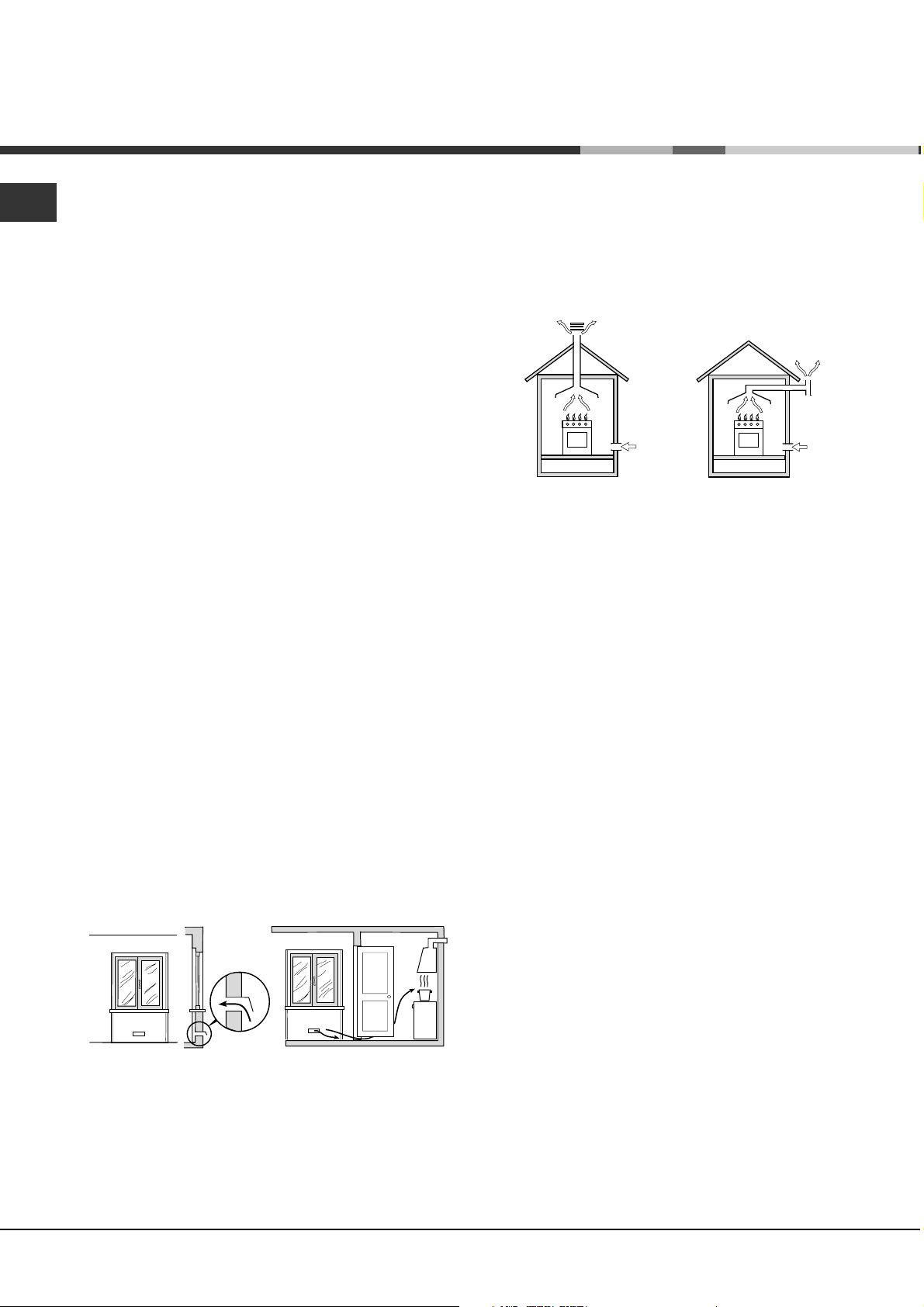
Disposing of combustion fumes
The disposal of combustion fumes should be
guaranteed using a hood connected to a safe and
efficient natural suction chimney, or using an electric
fan that begins to operate automatically every time
the appliance is switched on (see figure).
Fumes channelled Fumes channelled through
straight outside a chimney or a branched
flue system (reserved for
cooking appliances)
The liquefied petroleum gases are heavier than air
and collect by the floor, therefore all rooms containing
LPG cylinders must have openings leading outside
so that any leaked gas can escape easily.
LPG cylinders, therefore, whether partially or
completely full, must not be installed or stored in
rooms or storage areas that are below ground level
(cellars, etc.). Only the cylinder being used should
be stored in the room; this should also be kept well
away from sources of heat (ovens, chimneys,
stoves) that may cause the temperature of the
cylinder to rise above 50°C.
Positioning and levelling
It is possible to install the appliance alongside
cupboards whose height does not exceed that of the
hob surface.
Make sure that the wall in contact with the back of
the appliance is made from a non-flammable, heatresistant material (T 90°C).
A
Ventilation opening Increase in the gap between
for comburent air the door and the flooring
After prolonged use of the appliance, it is
advisable to open a window or increase the speed of
any fans used.
2
To install the appliance correctly:
Place it in the kitchen, the dining room or the bed-
sit (not in the bathroom).
If the top of the hob is higher than the cupboards,
the appliance must be installed at least 600 mm
away from them.
Page 3
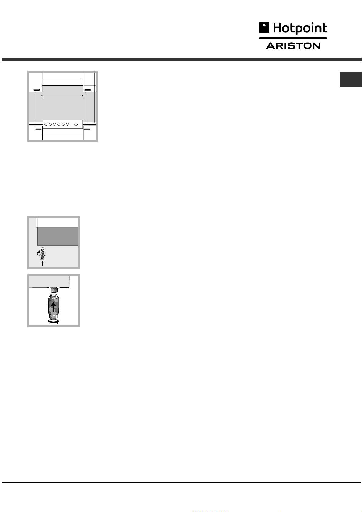
If the cooker is
installed underneath a
wall cabinet, there must
be a minimum distance
of 420 mm between
this cabinet and the top
700 mm. without hood
of the hob.
min. 650 mm. with hood
min.
mm.
420
Min.
HOOD
Min. mm.
600
420
Min. mm.
This distance should
be increased to 700
mm if the wall cabinets
are flammable (see figure).
Do not position blinds behind the cooker or less
than 200 mm away from its sides.
Any hoods must be installed according to the
instructions listed in the relevant operating
manual.
The socket can withstand the maximum power of the
appliance, which is indicated by the data plate.
The voltage is in the range between the values
indicated on the data plate.
The socket is compatible with the plug of the
appliance. If the socket is incompatible with the
plug, ask an authorised technician to replace it.
Do not use extension cords or multiple sockets.
Once the appliance has been installed, the power
supply cable and the electrical socket must be
easily accessible.
The cable must not be bent or compressed.
The cable must be checked regularly and replaced
by authorised technicians only.
GB
Levelling
If it is necessary to level the
appliance, screw the
adjustable feet into the places
provided on each corner of the
base of the cooker (see
figure).
The legs* fit into the slots on
the underside of the base of
the cooker.
Electrical connection
Install a standardised plug corresponding to the
load indicated on the appliance data plate (see
Technical data table).
The appliance must be directly connected to the mains
using an omnipolar circuit-breaker with a minimum
contact opening of 3 mm installed between the
appliance and the mains. The circuit-breaker must be
suitable for the charge indicated and must comply with
current electrical regulations (the earthing wire must not
be interrupted by the circuit-breaker). The supply cable
must be positioned so that it does not come into
contact with temperatures higher than 50°C at any point.
Before connecting the appliance to the power
supply, make sure that:
The appliance is earthed and the plug is compliant
with the law.
The manufacturer declines any liability should
these safety measures not be observed.
Gas connection
Connection to the gas network or to the gas cylinder
may be carried out using a flexible rubber or steel
hose, in accordance with current national legislation
and after making sure that the appliance is suited to
the type of gas with which it will be supplied (see the
rating sticker on the cover: if this is not the case see
below). When using liquid gas from a cylinder, install a
pressure regulator which complies with current national
regulations. To make connection easier, the gas
supply may be turned sideways*: reverse the position
of the hose holder with that of the cap and replace the
gasket that is supplied with the appliance.
Check that the pressure of the gas supply is
consistent with the values indicated in the Table of
burner and nozzle specifications (see below). This
will ensure the safe operation and durability of your
appliance while maintaining efficient energy
consumption.
Gas connection using a flexible rubber hose
Make sure that the hose complies with current
national legislation. The internal diameter of the hose
must measure: 8 mm for liquid gas supply; 13 mm
for methane gas supply.
Once the connection has been performed, make
sure that the hose:
Does not come into contact with any parts that
reach temperatures of over 50°C.
Is not subject to any pulling or twisting forces and
that it is not kinked or bent.
3
Page 4
GB
Does not come into contact with blades, sharp
corners or moving parts and that it is not
compressed.
Is easy to inspect along its whole length so that
its condition may be checked.
Is shorter than 1500 mm.
Fits firmly into place at both ends, where it will be
fixed using clamps that comply with current
regulations.
If one or more of these conditions is not fulfilled or
if the cooker must be installed according to the
conditions listed for class 2 - subclass 1 appliances
(installed between two cupboards), the flexible steel
hose must be used instead (see below).
Connecting a flexible jointless stainless steel
pipe to a threaded attachment
Make sure that the hose and gaskets comply with
current national legislation.
To begin using the hose, remove the hose holder on
the appliance (the gas supply inlet on the appliance
is a cylindrical threaded 1/2 gas male attachment).
3. Replace all the components by following the
above instructions in reverse.
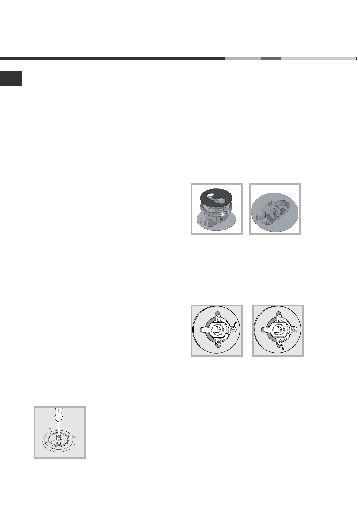
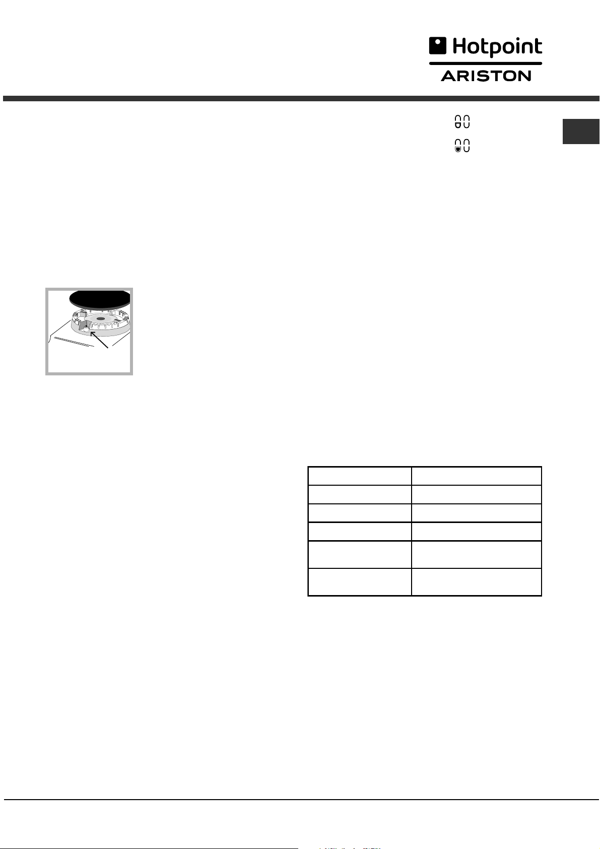
Replacing the nozzles on separate double flame
burners:
1. remove the grids and slide the burners from their
housings. The burner consists of 2 separate parts
(see figure);
2. unscrew the burers with a 7 mm wrench spanner. The
internal burner has a nozzle, the external burner has
two (of the same size). Replace the nozzle with models
suited to the new type of gas (see table 1).
3. replace all the components by repeating the steps in
reverse order.
Perform the connection in such a way that the hose
length does not exceed a maximum of 2 metres,
making sure that the hose is not compressed and
does not come into contact with moving parts.
Checking the tightness of the connection
When the installation process is complete, check
the hose fittings for leaks using a soapy solution.
Never use a flame.
Adapting to different types of gas
It is possible to adapt the appliance to a type of gas
other than the default type (this is indicated on the
rating label on the cover).
Adapting the hob
Replacing the nozzles for the hob burners:
1. Remove the hob grids and slide the burners off
their seats.
2. Unscrew the nozzles using
a 7 mm socket spanner (see
figure), and replace them with
nozzles suited to the new type
of gas (see Burner and nozzle
specifications table).
Adjusting the hob burners minimum setting:
1. Turn the tap to the minimum position.
2. Remove the knob and adjust the regulatory
screw, which is positioned inside or next to the tap
pin, until the flame is small but steady.
If the appliance is connected to a liquid gas
supply, the regulatory screw must be fastened as
tightly as possible:
3. While the burner is alight, quickly change the position
of the knob from minimum to maximum and vice versa
several times, checking that the flame is not
extinguished.
The hob burners do not require primary air adjustment.
After adjusting the appliance so it may be used with a
different type of gas, replace the old rating label with a
new one that corresponds to the new type of gas (these
labels are available from Authorised Technical Assistance
Centres).
4
Page 5
Should the gas pressure used be different (or vary
slightly) from the recommended pressure, a suitable
pressure regulator must be fitted to the inlet hose in
accordance with current national regulations relating
to regulators for channelled gas.
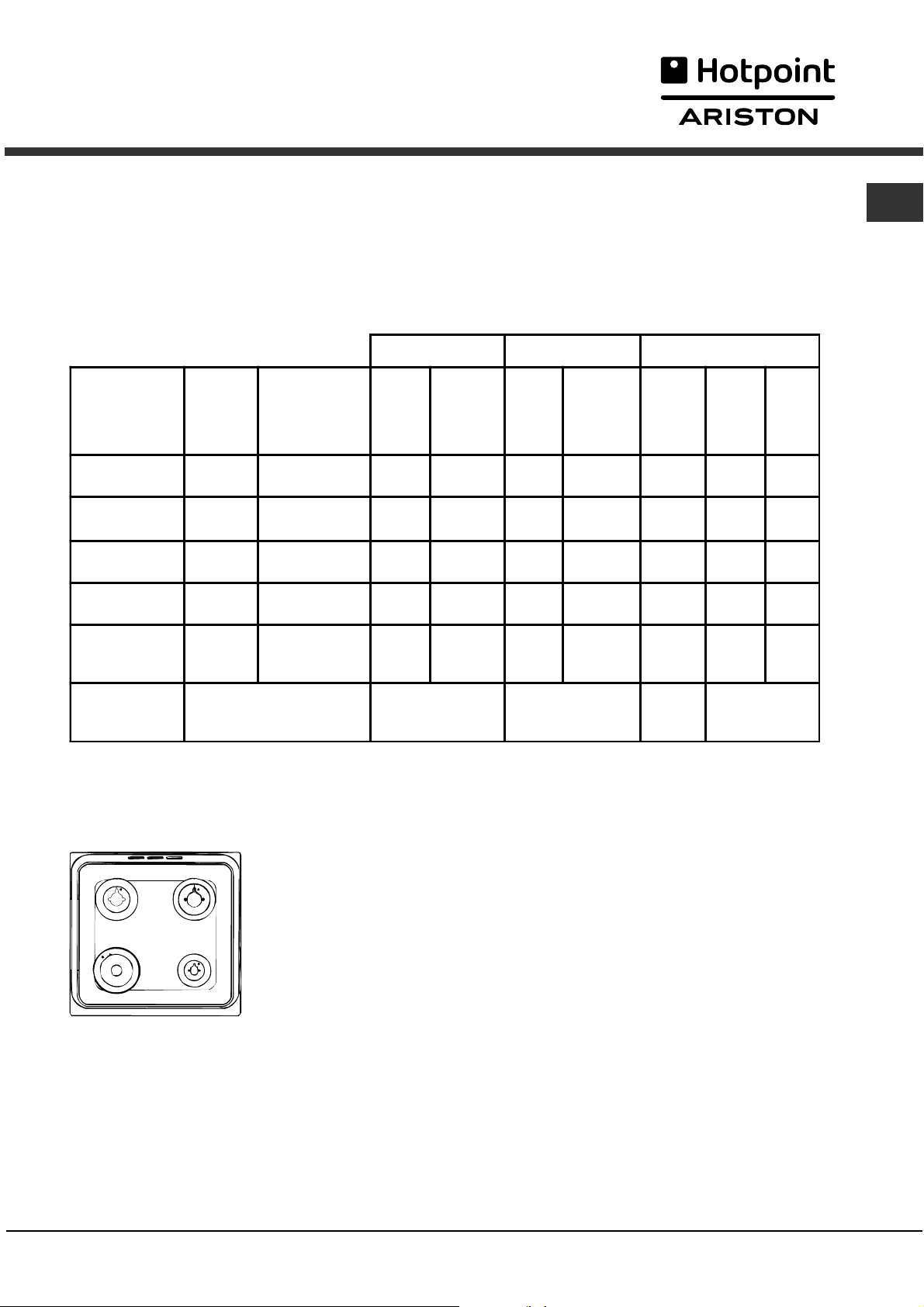
Table of burner and nozzle specifications
GB
Table 1
Burner Diameter
(mm)
Fast
(Large)(R)
Semi Fast
(Medium)(S)
Auxiliary
(Small)(A)
Double flame
(DCDR internal)
100 2,70 116 285 183 398 2,70 86 225
75 1,70 106 180 143 251 1,70 70 142
55 0,90 79 95 106 133 0,90 50 75
30 0,80 74 85 102 118 0,70 44 67
Double flame
(DCDR external)
130 3,50 110 370 165 516 4,10 70 292
2 nozzle
Supply
Pressures
Nominal (mb ar)
Minimum (mbar)
Maximum (mbar)
* A 0°C e 1013 mbar-dry
GZ 50 p.c.i. 35.9 MJ/m³
GZ 35 p.c.i. 25.8 MJ/m³
GPB-B p.c.i. 123.6 MJ/m³
Natural Gas GZ 50 Natural Gas GZ 35 GPB-B
Thermal power
(p.c.i.*)
Nozzle
1/100
Flow*
l/h
Nozzle
1/100
Flow*
l/h
Thermal
(p.c.i.*)
kW (mm) (mm) kW (mm)
16
20
25
10
13
16
gas
power
Nozzle
1/100
Flow*
g/h
29
36
44
S
R
DC
A
CX66SP6 U /HA
CX66SP6 X U /HA
5
Page 6
Description
of the appliance
GB
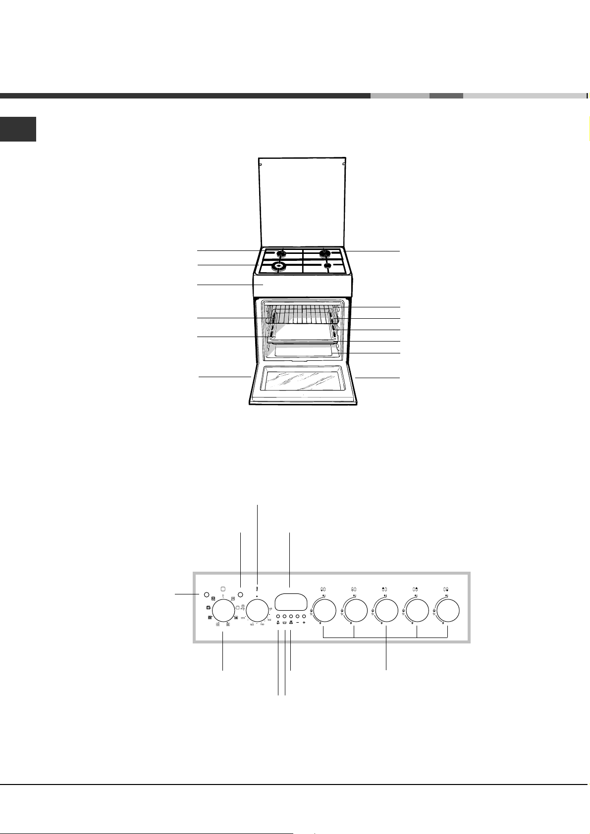
Overall view
DRIPPING PAN rack
Gas burner
Hob grid
Control panel
GRILL rack
Adjustable foot
Containment surface
for spills
GUIDE RAILS
for the sliding racks
position 5
position 4
position 3
position 2
position 1
Adjustable foot
Control panel
OPERATION
indicator light
THERMOSTAT
OVEN
SELECTOR
indicator light
knob
THERMOSTAT
knob
TIMER
button
Electronic
cooking
programmer
COOKING END
TIME button
COOKING TIME
button
Hob BURNER
control knobs
6
Page 7
Start-up and use
Using the hob
Lighting the burners
For each BURNER knob there is a complete ring
showing the strength of the flame for the relevant burner.
To light one of the burners on the hob:
1. Bring a flame or gas lighter close to the burner.
2. Press the BURNER knob and turn it in an
anticlockwise direction so that it is pointing to the
maximum flame setting E.
3. Adjust the intensity of the flame to the desired level
by turning the BURNER knob in an anticlockwise
direction. This may be the minimum setting C, the
maximum setting E or any position in between the two.
If the appliance is fitted with
an electronic lighting device*
(see figure), press the
BURNER knob and turn it in
an anticlockwise direction,
towards the maximum flame
setting, until the burner is lit.
The burner may be
extinguished when the knob is released. If this
occurs, repeat the operation, holding the knob down
for a longer period of time.
If the flame is accidentally extinguished, switch off
the burner and wait for at least 1 minute before
attempting to relight it.
If the appliance is equipped with a flame failure
safety device*, press and hold the BURNER knob
for approximately 2-3 seconds to keep the flame
alight and to activate the device.
The knob marked by the symbol
external burner;
The knob marked by the symbol
internal burner.
To turn on one of the rings, press the relative knob in
all the way and turn it anti-clockwise to the high
setting E. The burner is fitted with an electronic
igniter that automatically starts when the knob is
pressed in.
Since the burner is equipped with a safety device,
after lighting the burner keep the knob pressed in for
about 2-3 seconds to allow the device which keeps
the flame lit automatically to heat up.
The selected burner can be regulated using the
corresponding knob, as follows:
Off
E Maximum
C Minimum
To switch off the burner, turn the knob in a clockwise
direction until it stops (when reaches the position).
Practical advice on using the burners
For the burners to work in the most efficient way
possible and to save on the amount of gas
consumed, it is recommended that only pans that
have a lid and a flat base are used. They should
also be suited to the size of the burner:
Burner ø Cookware diameter (cm)
Rapid (R) 24 - 26
Semi-Rapid (S) 16 - 20
operates the
operates the
GB
To switch the burner off, turn the knob until it
reaches the stop position .
The separate double flame burner*
This burner consists of two concentric burners which
can operate either together or separately.
Use of the double flame on the maximum setting
gives a very high power which reduces cooking
times with respect to conventional burners.
Moreover the double flame crown provides a more
uniform distribution of heat on the bottom of the pan,
when using both burners on minimum.
To ensure
its full potential, never set the inside ring to
minimum and the outside ring to maximum
same time.
Pots and pans of all sizes can be used. In the case
of the smaller pots and pans we recommend the use
of only the internal burner.
There is a separate control knob for each of the
separate double flame burners.
that the double-flame burner is used to
at the
Auxilliary (A) 10 - 14
Double flame (DCDR
internal)
Double flame (DCDR
external)
To identify the type of burner, please refer to the
diagrams contained in the Burner and nozzle
specifications.
For models equipped with a reducer grid, the latter
must be used only for the auxiliary burner, when
pans with a diameter of less than 12 cm are used.
On the models supplied with a reducer shelf,
remember that this should be used only for the
Double flame internal (DCDR internal) burner when
you use casserole dishes with a diameter under 12
cm.
Only available in certain models.
*
10 -14
26 - 28
7
Page 8
GB
Using the oven
The first time you use your appliance, heat the empty
oven with its door closed at its maximum temperature
for at least half an hour. Ensure that the room is well
ventilated before switching the oven off and opening
the oven door. The appliance may emit a slightly
unpleasant odour caused by protective substances
used during the manufacturing process burning away.
Before operating the product, remove all plastic film
from the sides of the appliance.
Never put objects directly on the bottom of the oven;
this will avoid the enamel coating being damaged.
Should the appliance be equipped with an
electronic programmer, to use the electric oven, just
press buttons
symbol will appear on the display) before selecting
the desired cooking function.
1. Select the desired cooking mode by turning the
SELECTOR knob.
2. Select the recommended temperature for the
cooking mode or the desired temperature by turning
the THERMOSTAT knob.
A list detailing cooking modes and suggested
cooking temperatures can be found in the relevant
table (see Oven cooking advice table).
During cooking it is always possible to:
Change the cooking mode by turning the
SELECTOR knob.
Change the temperature by turning the
THERMOSTAT knob.
Stop cooking by turning the SELECTOR knob to
the 0 position.
Always place cookware on the rack(s) provided.
THERMOSTAT indicator light
When this is illuminated, the oven is generating
heat. It switches off when the inside of the oven
reaches the selected temperature. At this point the
light illuminates and switches off alternately,
indicating that the thermostat is working and is
maintaining the temperature at a constant level.
and at the same time (the
Oven light
This is switched on by turning the SELECTOR knob
to any position other than 0. It remains lit as long as
the oven is operating. By selecting
the light is switched on without any of the heating
elements being activated.
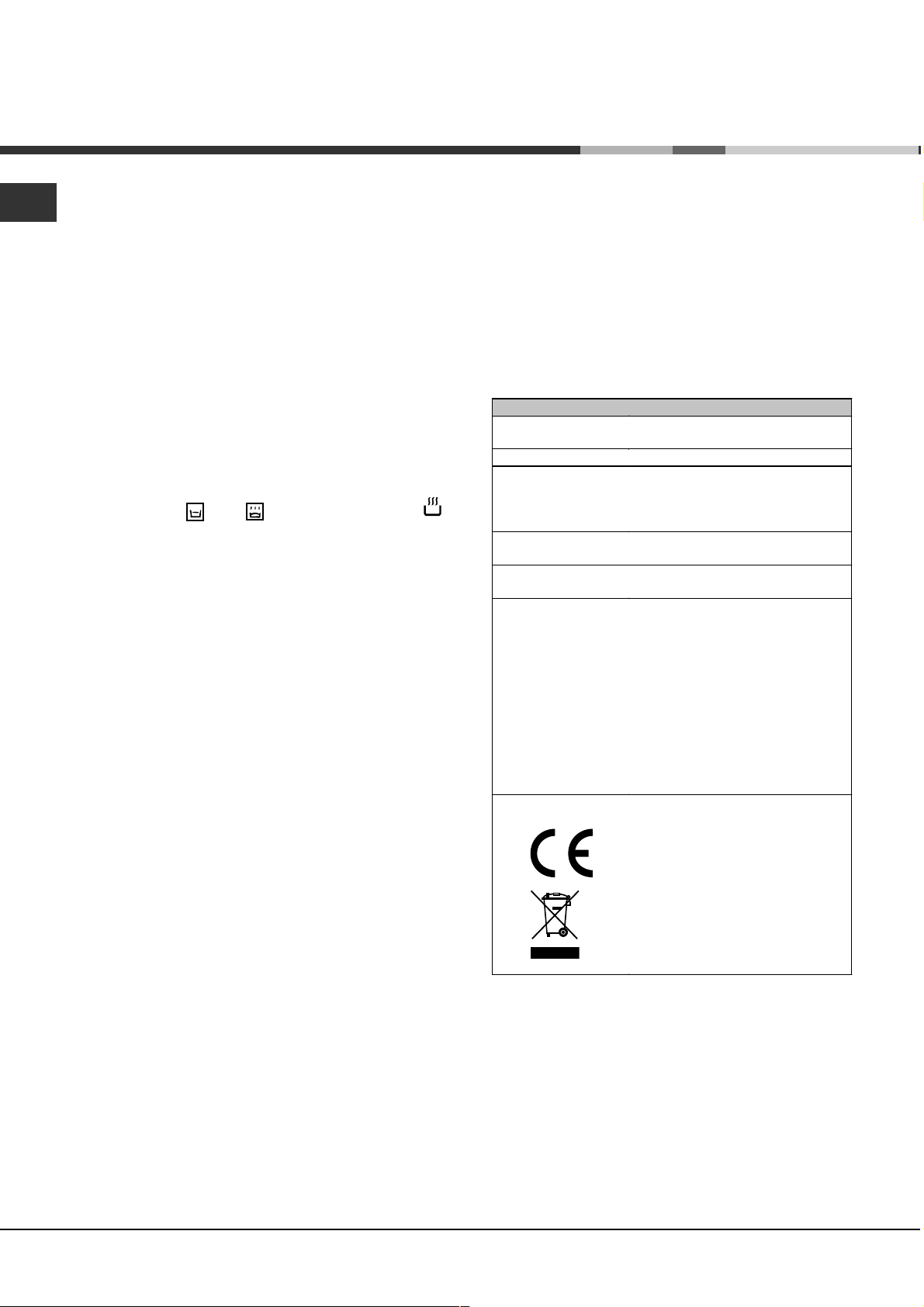
TECHNICAL DATA
Oven dimensions
(HxWxD)
Volume
Usef ul
measurements
relating to the oven
compartment
Burners
Voltage and
frequency
ENERGY LABEL
32x43.5x40 cm
56 l
width 42 cm
depth 44 cm
height 8.5 cm
may be adapted for use with any
type of gas shown on the data plate
see data plate
Directive 2002/40/EC on the label
of electric ovens.
Regulation EN 50304
Energy consumption for Natural
convection heating mode:
X
Traditional mode;
Declared energy consumption for
Forced convection Class
heating mode:
EC Directives: 73/23/EEC dated
19/02/73 (Low Voltage) and
subsequent amendments -
89/336/EEC dated 03/05/89
(Electromagnetic Compatibility)
and subsequent amendments -
90/369/EEC dated 29/06/90 (Gas)
and subsequent amendments -
93/68/EEC dated 22/07/93 and
subsequent amendments
2002/96/EC.
with the knob,
8
u
Baking.
-
OPERATION indicator light
When this is illuminated, the oven is generating
heat.
8
Page 9
Cooking modes
! A temperature value can be set for all cooking
modes between 50°C and Max, except for
more than one rack simultaneously, switch the
position of the dishes halfway through the cooking
process.
GB
BARBECUE (recommended: set only to MAX
power level);
GRATIN (recommended: do not exceed 200°C).
TRADITIONAL OVEN mode
Both the top and bottom heating elements will come
on. With this traditional cooking mode, it is best to
use one cooking rack only: if more than one rack is
used, the heat distribution will be uneven.
BAKING mode
The rear heating element and the fan come on,
guaranteeing the distribution of heat delicately and
uniformly throughout the oven. This mode is ideal for
baking and cooking temperature sensitive foods
such as cakes that need to rise and to prepare
certain tartlets on 3 shelves simultaneously.
FAST COOKING mode
The heating elements and the fan come on,
guaranteeing the distribution of heat consistently
and uniformly throughout the oven.
Pre-heating is not necessary for this cooking mode.
This mode is especially recommended for cooking
pre-packed food quickly (frozen or pre-cooked). The
best results are obtained if you use one cooking
rack only.
BARBECUE mode
The top heating element and the rotisserie (where
present) come on. The high and direct temperature of
the grill is recommended for food that requires high
surface temperature.
GRATIN mode
The top heating element as well as the fan and the
rotisserie (where present) come on. This combination
of features increases the effectiveness of the
unidirectional thermal radiation of the heating
elements through forced circulation of the air
throughout the oven.
This helps prevent food from burning on the surface,
allowing the heat to penetrate right into the food.
! In the BARBECUE and GRATIN cooking modes
with the oven door closed.
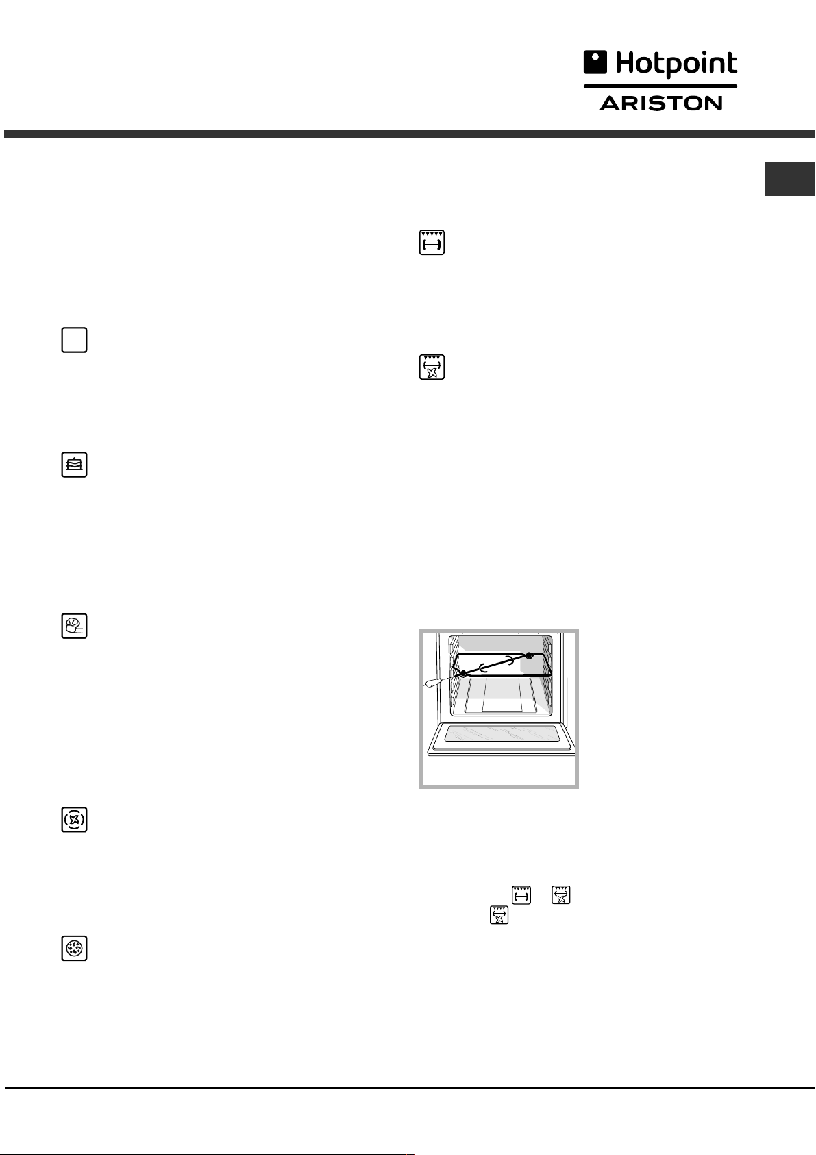
Spit roast (only available in certain models)
To operate the spit roast
function (see diagram)
proceed as follows:
MULTI-COOKING mode
All the heating elements (top, bottom and circular),
as well as the fan, will come on. Since the heat
remains constant throughout the oven, the air cooks
and browns food uniformly. A maximum of two racks
may be used at the same time.
PIZZA mode
The heating elements (bottom and circular) and the
fan come on. This combination heats the oven
rapidly by producing a considerable amount of heat,
particularly from the bottom element. If you use
1. Place the dripping pan in position 1.
2. Place the rotisserie support in position 3 and insert
the spit in the hole provided on the back panel of
the oven.
3. Start the rotisserie using the SELECTOR knob to
select mode
! When the
the door is opened.
or .
mode is activated, the spit will stop if
9
Page 10

GB
Practical cooking advice
! Do not place racks in position 1 and 5 during fan-
assisted cooking. Excessive direct heat can burn
temperature sensitive foods.
! In the BARBECUE and GRATIN cooking modes,
particularly when using the rotisserie, place the
dripping pan in position 1 to collect cooking
residues (fat and/or grease).
MULTI-COOKING
Use position 2 and 4, placing the food that
requires more heat on 2.
Place the dripping pan on the bottom and the rack
on top.
BARBECUE
Insert the rack in position 3 or 4. Place the food in
the centre of the rack.
We recommend that you set the maximum power
level. The top heating element is regulated by a
thermostat and may not always be on.
PIZZA MODE
Use a light aluminium pizza pan. Place it on the
rack provided.
For a crispy crust, do not use the dripping pan
(prevents crust from forming by extending
cooking time).
To set the timer proceed as follows:
1. press the TIMER button
H. The display shows:
N.
2. Press the * and ) buttons to set the desired
time.
3. When the buttons are released the timer begins
counting down and the current time appears on the
display.
R
4. After the time has elapsed a buzzer will sound,
and this can be switched off by pressing any button
(except the
switch off.
The timer does not switch the oven on or off.
Adjusting the volume of the buzzer
After selecting and confirming the clock settings, use the
button to adjust the volume of the alarm buzzer.
)
Setting the cooking time with a delayed start
First decide which cooking mode you wish to use and set
a suitable temperature using the SELECTOR and
THERMOSTAT knobs on the oven.
At this point it is possible to set the cooking time:
1. Press the COOKING TIME button
2. Within 4 seconds of having pressed this button, set the
desired amount of time by pressing the
If, for example, you wish to set a cooking time of 30
minutes, the display will show:
and ) buttons). The symbol
*
.
$
*
will
H
and ) buttons.
If the pizza has a lot of toppings, we recommend
adding the mozzarella cheese on top of the pizza
halfway through the cooking process.
Planning cooking with the electronic
programmer
Setting the clock
After the appliance has been connected to the power
supply, or after a blackout, the display will automatically
reset to 0:00 and begin to blink. To set the time:
1. Press the COOKING TIME button
COOKING END TIME
2. Within 4 seconds of having pressed these buttons, set
the exact time by pressing the
button advances the hours and the ) button decreases
the hours.
Once the time has been set, the programmer
automatically switches to manual mode.
Setting the timer
The timer enables a countdown to be set, when the time
has elapsed a buzzer sounds.
simultaneously.
%
*
and the
$
and ) buttons. The
*
N.
3. 4 seconds after the buttons are released, the
current time (for example 10.00) reappears on the
display with the symbol
Next the desired cooking end time must be set:
4. Press the END COOKING TIME button
5. Within 4 seconds of having pressed this button,
adjust the cooking end time by pressing the
buttons. If, for example, you want cooking to end
)
at 13.00, the display shows:
and the letter A (AUTO).
m
%
.
and
*
O
6. 4 seconds after the buttons are released, the
current time (for example 10.00) reappears on the
display with the letter A (AUTO).
P
At this point, the oven is programmed to switch on
automatically at 12:30 and switch off after 30
minutes, at 13.00.
10
Page 11

Setting the cooking time with an immediate start
Follow the above procedure for setting the cooking time
(points 1-3).
When the letter A appears, this indicates that both the
cooking time and the end cooking time have been
programmed in AUTO mode. To restore the oven to
manual operation, after each AUTO cooking mode press
the COOKING TIME
buttons simultaneously.
The symbol
the entire duration of the cooking programme.
The set cooking duration can be displayed at any time by
pressing the COOKING TIME button
cooking end time may be displayed by pressing the END
COOKING TIME button
elapsed a buzzer sounds. To stop it, press any button
apart from the
m
*
and END COOKING TIME
$
will remain lit, along with the oven, for
, and the
$>$
. When the cooking time has
%
and ) buttons.
%
Cancelling a previously set cooking programme
Press the COOKING TIME button
COOKING END TIME
Correcting or cancelling previously set data
The data entered can be changed at any time by
pressing the corresponding button (TIMER, COOKING
TIME or COOKING END TIME) and the
When the cooking time data is cancelled, the cooking end
time data is also cancelled automatically, and vice versa.
If the oven has already been programmed, it will not
accept cooking end times which are before the start of the
programmed cooking process.
simultaneously.
%
and the
$
or ) button.
*
GB
11
Page 12

GB
Oven cooking advice table
Cooking
modes
Traditional
Oven
Baking
Mode
Fast
cooking
Multi-
cooking
Pizza Mode
Barbecue
Gratin
Foods Weight
Duck
Roast veal or beef
Pork roast
Biscuits (short pastry)
Tarts
Tarts
Fruit cakes
Plum cake
Sponge cake
Stuffed pancakes (on 2 racks)
Small cakes (on 2 racks)
Cheese puffs (on 2 racks)
Cream puffs (on 3 racks)
Biscuits (on 3 racks)
Meringues (on 3 racks )
Frozen food
Pizza
Courgette and prawn pie
Country style spinach pie
Turnovers
Lasagne
Golden Rolls
Chicken morsels
Pre-cook ed food
Golden chicken wings
Fresh Food
Biscuits (short pastry)
Plum cake
Cheese puffs
Pizza (on 2 racks)
Lasagne
Lamb
Roast chicken + potatoes
Mackerel
Plum cake
Cream puffs (on 2 racks)
Biscuits (on 2 racks)
Sponge cake (on 1 rack)
Sponge cake (on 2 racks)
Savoury pies
Pizza
Roast veal or beef
Chicken
Soles and cuttlefish
Squid and prawn kebabs
Cuttlefish
Cod filet
Grilled vegetables
Veal steak
Sausages
Hamburgers
Mackerels
Toasted sandwiches (or toast)
Wit h rotisserie
Veal on the spit
Chicken on the spit
Lamb on the spit
Grilled chicken
Cuttlefish
With rotisserie
Veal on the spit
Lamb on the spit
Chicken (on the spit) +
potatoes (roasted)
(where present)
(where present)
(in kg)
1
1
1
-
1
0.5
1
0.7
0.5
1.2
0.6
0.4
0.7
0.7
0.5
0.3
0.4
0.5
0.3
0.5
0.4
0.4
0.4
0.3
0.6
0.2
1
1
1
1+1
1
1
0.5
0.5
0.5
1
1.5
0.5
1
1
0.7
0.6
0.6
0.8
0.4
0.8
0.6
0.6
1
4 and 6
1.0
1.5
1.0
1.5
1.5
1.5
1.5
1.5
-
Rack Position Pre-heating
time
(minutes)
3
3
3
3
3
3
2 or 3
3
3
2 and 4
2 and 4
2 and 4
1 and 3 and 5
1 and 3 and 5
1 and 3 and 5
2
2
2
2
2
2
2
2
2
2
2
2 and 4
3
2
and 4
2
2
2
2 and 4
2 and 4
2
2 and 4
3
3
2
2 or 3
4
4
4
4
3 or 4
4
4
4
4
4
-
-
2
2
2
2
2
15
15
15
15
15
15
15
15
15
15
15
15
15
15
15
-
-
-
-
-
-
-
-
-
-
15
10
10
15
10
10
10
10
10
10
15
15
10
10
-
-
-
-
-
-
-
-
-
-
5
5
5
10
10
5
5
5
5
Recommended
temperature
200
200
200
180
180
180
180
180
160
200
190
210
180
180
90
250
200
220
200
200
180
220
200
200
180
210
230
180
180
200
180
170
190
180
170
170
200
220
220
180
Max
Max
Max
Max
Max
Max
Max
Max
Max
Max
Max
Max
Max
200
200
200
200
200
200
Cooking
time
(minutes)
65-75
70-75
70-80
15-20
30-35
20-30
40-45
40-50
25-30
30-35
20-25
15-20
20-25
20-25
180
12
20
30-35
25
35
25-30
15-20
20-25
15-18
45
10-12
15-20
30-35
40-45
60-70
30-35
40-50
20-25
10-15
15-20
20-25
25-30
15-20
25-30
60-70
10-12
8-10
10-15
10-15
15-20
15-20
15-20
10-12
15-20
3-5
80-90
70-80
70-80
55-60
30-35
70-80
70-80
70-75
70-75
12
Page 13

Precautions and tips
This appliance has been designed and manufactured
in compliance with international safety standards.
The following warnings are provided for safety
reasons and must be read carefully.
General safety
The appliance was designed for domestic use
inside the home and is not intended for
commercial or industrial use.
The appliance must not be installed outdoors, even
in covered areas. It is extremely dangerous to
leave the appliance exposed to rain and storms.
Do not touch the appliance with bare feet or with
wet or damp hands and feet.
The appliance must be used by adults only for the
preparation of food, in accordance with the
instructions provided in this booklet.
The instruction booklet accompanies a class 1
(insulated) or class 2 - subclass 1 (recessed
between 2 cupboards) appliance.
Do not touch the heating elements or certain
parts of the oven door when the appliance is in
use;
these parts become extremely hot. Keep
children well away from the appliance.
Make sure that the power supply cables of other
electrical appliances do not come into contact
with the hot parts of the oven.
The openings used for the ventilation and
dispersion of heat must never be covered.
Always use oven gloves when placing cookware
in the oven or when removing it.
Do not use flammable liquids (alcohol, petrol,
etc...) near the appliance while it is in use.
Never perform any cleaning or maintenance work
without having disconnected the appliance from
the electricity mains.
If the appliance breaks down, under no
circumstances should you attempt to perform the
repairs yourself. Repairs carried out by
inexperienced persons may cause injury or further
malfunctioning of the appliance. Contact
Assistance.
Do not rest heavy objects on the open oven door.
Disposal
When disposing of packaging material: observe
local legislation so that the packaging may be
reused.
The European Directive 2002/96/EC relating to
Waste Electrical and Electronic Equipment
(WEEE) states that household appliances should
not be disposed of using the normal solid urban
waste cycle. Exhausted appliances should be
collected separately in order to optimise the cost
of re-using and recycling the materials inside the
machine, while preventing potential damage to
the atmosphere and to public health. The
crossed-out dustbin is marked on all products to
remind the owner of their obligations regarding
separated waste collection.
For further information relating to the correct
disposal of exhausted household appliances,
owners may contact the public service provided
or their local dealer.
Respecting and conserving the
environment
GB
Do not place flammable material in the lower
storage compartment or in the oven itself. if the
appliance is switched on accidentally, they could
catch fire.
The internal surfaces of the compartment (where
present) may become hot.
Always make sure the knobs are in the
when the appliance is not in use.
When unplugging the appliance, always pull the
plug from the mains socket; do not pull on the
cable.
position
You can help to reduce the peak load of the
electricity supply network companies by using the
oven in the hours between late afternoon and the
early hours of the morning.
Always keep the oven door closed when using the
BARBECUE and GRATIN modes: to attain best
results and to save energy (approximately 10%).
Check the door seals regularly and wipe them
clean to ensure they are free of debris so that
they adhere properly to the door, thus avoiding
heat dispersion.
13
Page 14

Care and maintenance
GB
Switching the appliance off
Disconnect your appliance from the electricity
supply before carrying out any work on it.
Cleaning the appliance
Never use steam cleaners or pressure cleaners on
the appliance.
The stainless steel or enamel-coated external
parts and the rubber seals may be cleaned using
a sponge that has been soaked in lukewarm water
and neutral soap. Use specialised products for
the removal of stubborn stains. After cleaning,
rinse well and dry thoroughly. Do not use abrasive
powders or corrosive substances.
The hob grids, burner caps, flame spreader rings
and burners may be removed to make cleaning
easier; wash them in hot water and non-abrasive
detergent, making sure all burnt-on residue is
removed before drying them thoroughly.
Inspecting the oven seals
Check the door seals around the oven regularly. If
the seals are damaged, please contact your nearest
Authorised After-sales Service Centre. We
recommend that the oven is not used until the seals
have been replaced.
Replacing the oven light bulb
1. After disconnecting the oven
from the electricity mains,
remove the glass lid covering
the lamp socket (see figure).
2. Remove the light bulb and
replace it with a similar one:
voltage 230 V, wattage 25 W,
cap E 14.
3. Replace the lid and reconnect the oven to the
electricity supply.
Gas tap maintenance
Clean the terminal part of the flame failure safety
devices* frequently.
The inside of the oven should ideally be cleaned
after each use, while it is still lukewarm. Use hot
water and detergent, then rinse well and dry with
a soft cloth. Do not use abrasive products.
Clean the glass part of the oven door using a
sponge and a non-abrasive cleaning product,
then dry thoroughly with a soft cloth. Do not use
rough abrasive material or sharp metal scrapers
as these could scratch the surface and cause the
glass to crack.
The accessories can be washed like everyday
crockery, and are even dishwasher safe.
Do not close the cover when the burners are alight
or when they are still hot.
Over time, the taps may become jammed or difficult
to turn. If this occurs, the tap must be replaced.
This procedure must be performed by a
qualified technician authorised by the
manufacturer.
Assistance
Never use the services of an unauthorised
technician.
Please have the following information to hand:
The type of problem encountered.
The appliance model (Mod.).
The serial number (S/N).
The latter two pieces of information can be found on
the data plate located on the appliance.
14
Only available in certain models.
*
Page 15

Instrukcja obs³ugi
GB
English,1
CX66SP6 U /HA
CX66SP6 U /HA
PL
Polski, 15
KUCHENKA I PIEKARNIK
PL
Spis treci
Instalacja, 16-19
Ustawienie i wypoziomowanie
Pod³¹czenie do sieci elektrycznej
Pod³¹czenie gazu
Dostosowanie do ró¿nych rodzajów gazu
Tabela charakterystyk palników i dysz
Tabela charakterystyk
Opis urz¹dzenia, 20
Widok ogólny
Panel kontrolny
Uruchomienie i u¿ytkowanie, 21-26
U¿ytkowanie p³yty grzejnej
U¿ytkowanie piekarnika
Programy pieczenia
Praktyczne porady dotycz¹ce pieczenia
Tabela pieczenia w piekarniku
Zalecenia i rodki ostro¿noci, 27
Ogólne zasady bezpieczeñstwa
Zalecenia dotycz¹ce odpadów
Oszczêdnoæ i ochrona rodowiska
Konserwacja i utrzymanie, 28
Od³¹czenie pr¹du elektrycznego
Czyszczenie urz¹dzenia
Wymiana ¿arówki owietleniowej w piekarniku
Konserwacja kurków gazowych
Serwis Techniczny
15
Page 16

Instalacja
PL
Nale¿y zachowaæ niniejsz¹ instrukcjê, aby móc z
niej korzystaæ w ka¿dej chwili. W przypadku
sprzeda¿y, odst¹pienia lub przeniesienia urz¹dzenia
nale¿y upewniæ siê, czy instrukcja zosta³a
przekazana wraz z nim.
Nale¿y uwa¿nie przeczytaæ instrukcjê: zawiera ona
wa¿ne informacje dotycz¹ce instalacji, u¿ytkowania i
bezpieczeñstwa.
Instalacja urz¹dzenia powinna zostaæ wykonana
zgodnie z niniejszymi instrukcjami i przez
wykwalifikowany personel.
Wszelkie dzia³ania w zakresie regulacji lub
konserwacji musz¹ byæ wykonywane przy kuchence
od³¹czonej od zasilania elektrycznego.
Wentylacja pomieszczeñ
Urz¹dzenie mo¿e zostaæ zainstalowane wy³¹cznie w
pomieszczeniach ze sta³¹ wentylacj¹, zgodnie z
obowi¹zuj¹cymi normami krajowymi. W
pomieszczeniu, w którym jest instalowane
urz¹dzenie, musi byæ zapewniony taki dop³yw
powietrza, jaki jest niezbêdny dla prawid³owego
spalania gazu (natê¿enie przep³ywu powietrza nie
powinno byæ ni¿sze od 2 m
mocy). Wloty powietrza, zabezpieczone przez kratki,
powinny mieæ przewód o przekroju u¿ytkowym co
najmniej 100 cm
tak, aby nie mog³y ulec nawet czêciowemu zatkaniu
(patrz rysunek A).
Wymiar tych wlotów powinien zostaæ zwiêkszony o
100% do minimum 200 cm
urz¹dzenia nie posiada urz¹dzenia
zabezpieczaj¹cego przed brakiem p³omienia i kiedy
dop³yw powietrza nastêpuje w sposób poredni z
przyleg³ych pomieszczeñ (patrz rysunek B) o ile
nie s¹ one czêciami wspólnymi budynku,
pomieszczeniami zagro¿onymi po¿arem lub
sypialniami wyposa¿onych w przewód
wentylacyjny z wyjciem na zewn¹trz, jak opisano
powy¿ej.
A Pomieszczenie przyleg³e B Pomieszczenie do wentylacji
2
i powinny zostaæ rozmieszczone
3
/h na kW zainstalowanej
2
jeli p³yta robocza
Odprowadzanie spalin
Odprowadzanie spalin musi byæ zapewnione przez
okap po³¹czony z kominem o ci¹gu naturalnym i o
sprawnym dzia³aniu, lub przez wentylator
elektryczny, który w³¹cza siê automatycznie przy
ka¿dym uruchomieniu urz¹dzenia (patrz rysunki).
Odprowadzanie
bezporednio na
zewn¹trz
Skroplone gazy pochodne ropy naftowej, ciê¿sze od
powietrza, opadaj¹ w dó³, dlatego pomieszczenia, w
których znajduj¹ siê butle LPG, powinny byæ
wyposa¿one w otwory wychodz¹ce na zewn¹trz,
umo¿liwiaj¹ce odp³yw ewentualnych wycieków gazu
do³em.
Butle LPG - niezale¿nie od tego, czy s¹ puste, czy
czêciowo nape³nione - nie powinny byæ instalowane
ani sk³adowane w pomieszczeniach lub wnêkach
po³o¿onych poni¿ej poziomu pod³ogi (piwnice, itp.).
W pomieszczeniu nale¿y przechowywaæ jedynie
aktualnie u¿ytkowan¹ butlê, z dala od róde³ ciep³a
(piece, kominki, piecyki), mog¹cych doprowadziæ do
wzrostu jej temperatury powy¿ej 50°C.
Odprowadzanie przez komin
lub rozga³êziony kana³
dymowy (wy³¹cznie do
urz¹dzeñ kuchennych)
Ustawienie i wypoziomowanie
Istnieje mo¿liwoæ zainstalowania urz¹dzenia obok
mebli, których wysokoæ nie przekracza wysokoci
p³yty roboczej.
A
Otwarcie wentylacji dla
powietrza do spalania
Po d³u¿szym u¿ytkowaniu urz¹dzenia zaleca siê
otwarcie okna lub zwiêkszenie prêdkoci
ewentualnych wentylatorów.
16
Zwiêkszenie szczeliny
pomiêdzy drzwiami a
pod³og¹
Nale¿y upewniæ siê, czy ciana stykaj¹ca siê z
ty³em urz¹dzenia wykonana jest z materia³u
niepalnego i odpornego na ciep³o (T 90°C).
W celu zapewnienia prawid³owej instalacji:
ustawiæ urz¹dzenie w kuchni, w jadalni lub w
innym pomieszczeniu (nie w ³azience);
jeli p³aszczyzna kuchenki jest wy¿sza w
stosunku do p³aszczyzny mebli, powinny one
zostaæ umieszczone w odleg³oci co najmniej 600
mm od urz¹dzenia;
Page 17

jeli kuchenka jest
HOOD
instalowana pod szafk¹
wisz¹c¹, powinna ona
Min. mm.
mm.
420
Min.
600
420
Min. mm.
znajdowaæ siê w
odleg³oci minimum
420 mm od p³yty
kuchenki. Odleg³oæ ta
700 mm. without hood
min. 650 mm. with hood
min.
powinna wynosiæ 700
mm, jeli szafki
wisz¹ce s¹ ³atwopalne
(patrz rysunek);
nie umieszczaæ zas³on za kuchenk¹ ani w
odleg³oci mniejszej ni¿ 200 mm od jej krawêdzi;
ewentualne okapy powinny zostaæ zainstalowane
wed³ug zaleceñ odpowiedniej instrukcji.
Wypoziomowanie
Jeli konieczne jest
wypoziomowanie urz¹dzenia,
nale¿y przykrêciæ nó¿ki
regulacyjne, dostarczone jako
wyposa¿enie dodatkowe, w
odpowiednich gniazdach
umieszczonych w rogach
podstawy kuchenki (patrz
rysunek).
Nó¿ki mocowane s¹ w
otworach pod podstaw¹
kuchenki.
Pod³¹czenie do sieci elektrycznej
Zamocowaæ na przewodzie znormalizowan¹ wtyczkê,
dostosowan¹ do obci¹¿eñ wskazanych na tabliczce
znamionowej umieszczonej na urz¹dzeniu (patrz
tabela Dane techniczne). W przypadku
bezporedniego pod³¹czenia do sieci konieczne jest
zainstalowanie pomiêdzy urz¹dzeniem a sieci¹
wy³¹cznika wielobiegunowego z minimalnym
otwarciem pomiêdzy stykami wynosz¹cym 3 mm,
dostosowanego do obci¹¿eñ i odpowiadaj¹cego
obowi¹zuj¹cym normom krajowym (przewód
uziemienia nie powinien byæ przerwany przez
wy³¹cznik). Przewód zasilania powinien byæ
umieszczony tak, aby w ¿adnym punkcie jego
temperatura nie przekracza³a temperatury otoczenia
o 50°C.
Przed wykonaniem pod³¹czenia nale¿y upewniæ siê,
czy:
gniazdko posiada odpowiednie uziemienie i jest
zgodne z obowi¹zuj¹cymi przepisami;
gniazdko jest w stanie wytrzymaæ maksymalne
obci¹¿enie mocy urz¹dzenia, wskazane na
tabliczce znamionowej;
napiêcie zasilania odpowiada wartociom
podanym na tabliczce znamionowej;
gniazdko jest kompatybilne z wtyczk¹ urz¹dzenia.
Jeli gniazdko nie jest kompatybilne, nale¿y
wymieniæ gniazdko lub wtyczkê; nie stosowaæ
przed³u¿aczy ani rozga³êników.
Po zainstalowaniu urz¹dzenia przewód elektryczny
i gniazdko pr¹du powinny byæ ³atwo dostêpne.
Przewód nie powinien byæ powyginany ani
zgnieciony.
Przewód musi byæ okresowo sprawdzany i
wymieniany wy³¹cznie przez autoryzowany personel
techniczny.
Producent nie ponosi ¿adnej
odpowiedzialnoci za skutki wynik³e z nie
przestrzegania powy¿szych zasad.
Pod³¹czenie gazu
Pod³¹czenie do sieci gazowej lub do butli gazowej
mo¿e byæ wykonane przy pomocy przewodu
giêtkiego gumowego lub stalowego, zgodnie z
obowi¹zuj¹cymi normami krajowymi, oraz po
upewnieniu siê, czy urz¹dzenie jest wyregulowane
odpowiednio dla typu gazu, którym bêdzie zasilane
(patrz etykieta kalibracyjna na pokrywie: w
przeciwnym razie patrz ni¿ej). W przypadku
zasilania p³ynnym gazem z butli nale¿y stosowaæ
regulatory cinienia zgodne z obowi¹zuj¹cymi
normami krajowymi. Dla u³atwienia pod³¹czenia
zasilanie gazem mo¿e byæ skierowane bocznie*:
zast¹piæ z³¹czkê przewodu giêtkiego zatyczk¹ i
wymieniæ uszczelkê, dostarczon¹ jako wyposa¿enie
dodatkowe.
W celu zapewnienia bezpieczeñstwa pracy,
odpowiedniego zu¿ycia energii i zwiêkszenia
trwa³oci urz¹dzenia, nale¿y siê upewniæ, czy
cinienie zasilania mieci siê w granicach
wskazanych w tabeli Charakterystyka palników i
dysz (patrz ni¿ej).
Pod³¹czenie gazu przy pomocy przewodu
gumowego
Sprawdziæ, czy przewód odpowiada obowi¹zuj¹cym
normom krajowym. Wewnêtrzna rednica przewodu
powinna wynosiæ: 8 mm przy zasilaniu gazem
p³ynnym; 13 mm przy zasilaniu metanem.
Po wykonaniu pod³¹czenia nale¿y upewniæ siê, czy
przewód:
nie styka siê w ¿adnym punkcie z czêciami,
które osi¹gaj¹ temperatury przekraczaj¹ce 50°C;
nie jest nara¿ony na naci¹gniêcie ani poskrêcanie
i nie ma na nim zagiêæ lub przewê¿eñ;
nie ma stycznoci z przedmiotami tn¹cymi,
ostrymi krawêdziami, ruchomymi czêciami, i nie
jest przygnieciony;
PL
17
Page 18

PL
jest ³atwo dostêpny na ca³ej d³ugoci, co
umo¿liwia wykonywanie kontroli jego stanu;
jego d³ugoæ wynosi mniej ni¿ 1500 mm;
jest dobrze umocowany na dwóch koñcach za
pomoc¹ odpowiednich zacisków mocuj¹cych,
zgodnych z obowi¹zuj¹cymi normami krajowymi.
Jeli nie mo¿e byæ spe³niony jeden lub kilka tych
warunków, albo jeli kuchenka jest instalowana
zgodnie z warunkami klasy 2 - podklasy 1
(urz¹dzenie umiejscowione pomiêdzy dwoma
meblami), nale¿y zastosowaæ przewód giêtki stalowy
(patrz ni¿ej).
Pod³¹czenie gazu przy pomocy przewodu
giêtkiego ze stali nierdzewnej o pe³nych
ciankach z gwintowanymi z³¹czami.
Sprawdziæ, czy przewód i uszczelki odpowiadaj¹
obowi¹zuj¹cym normom krajowym.
Aby zamontowaæ przewód, nale¿y usun¹æ z³¹czkê
przewodu giêtkiego, znajduj¹c¹ siê na urz¹dzeniu
(z³¹cze wejciowe gazu do urz¹dzenia jest
gwintowane gwintem gazowym 1/2 walcowym
mêskim).
Wykonaæ pod³¹czenie tak, aby ca³kowita d³ugoæ
przewodów nie przekracza³a 2 metrów, oraz upewniæ
siê, czy przewód nie styka siê z ruchomymi
czêciami i nie jest przygnieciony.
Wymiana dysz w palniku dwup³omieniowym z
niezale¿nymi p³omieniami
1. zdj¹æ kratki i wykrêciæ palniki z gniazd; palnik sk³ada siê
z dwóch oddzielnych czêci (patrz rysunki);
2. odkrêciæ dysze, pos³uguj¹c siê kluczem rurowym 7
mm. Palnik wewnêtrzny ma jedn¹ dyszê, palnik
zewnêtrzny ma dwie dysze (tej samej wielkoci).
Wymieniæ dysze na dostosowane do nowego rodzaju
gazu (patrz tabela 1).
3. przywróciæ na swoje miejsce wszystkie komponenty,
wykonuj¹c czynnoci w kolejnoci odwrotnej w
stosunku do powy¿szej sekwencji.
Regulacja minimum palników p³yty:
1. ustawiæ kurek w po³o¿eniu minimum;
2. zdj¹æ pokrêt³o i krêciæ rub¹ regulacyjn¹
znajduj¹c¹ siê wewn¹trz lub obok osi kurka a¿ do
uzyskania ma³ego regularnego p³omienia.
W przypadku gazów p³ynnych ruba regulacyjna
powinna byæ dokrêcona do koñca;
Kontrola szczelnoci
Po zakoñczeniu instalacji sprawdziæ szczelnoæ
wszystkich z³¹cz, stosuj¹c w tym celu roztwór
mydlany, nigdy p³omieñ.
Dostosowanie do ró¿nych rodzajów
gazu
Urz¹dzenie mo¿e byæ dostosowane do innego
rodzaju gazu ni¿ ten, którym jest aktualnie zasilane
(wskazany na etykiecie kalibracyjnej na pokrywie).
Dostosowanie p³yty grzejnej
Wymiana dysz palników p³yty:
1. zdj¹æ kratki i wykrêciæ palniki z gniazd;
2. odkrêciæ dysze, pos³uguj¹c siê kluczem rurowym
7 mm (patrz rysunek), i
wymieniæ je na te, które s¹
przystosowane do nowego
rodzaju gazu (patrz tabela
Charakterystyka palników i
dysz);
3. przywróciæ na swoje
miejsce wszystkie
komponenty, wykonuj¹c
czynnoci w kolejnoci odwrotnej w stosunku do
powy¿szej sekwencji.
3. sprawdziæ, czy podczas szybkiego obracania
pokrêt³em z po³o¿enia maksymalnego do
minimalnego nie nastêpuje ganiêcie palników.
Palniki p³yty nie wymagaj¹ regulacji powietrza
pierwotnego.
Po wykonaniu regulacji dla gazu innego ni¿
oryginalnie przewidziany nale¿y wymieniæ poprzedni¹
etykietê kalibracyjn¹ na etykietê odpowiadaj¹c¹
nowemu gazowi, dostêpn¹ w naszych
Autoryzowanych Centrach Obs³ugi Technicznej.
W sytuacji, gdy cinienie gazu jest inne (lub
zmienne) od przewidzianego, konieczne jest
zainstalowanie regulatora cinienia na przewodach
doprowadzaj¹cych, zgodnie z obowi¹zuj¹c¹ norm¹
krajow¹ dotycz¹c¹ kana³owych regulatorów gazu.
18
Page 19

Tabela „Charakterystyka palników i dysz”
(
PL
rednica
(w mm)
30 0,80 74 85 102 118 0,70 44 67
130 3,50 110 370 165 516 4,10 70 292
minimalne (mbar)
nominalne (mbar)
maksymalne (mbar)
Moc cieplna
(p.c.i.*)
kW
G20 (GZ50)
Dysza
1/100
(w mm)
Tabela 1 (dla Polski)
Palnik
Du¿y (R) 100 2.70 116 285 183 398 2,70 86 225
Pó³szybki (redni) (S) 75 1,70 106 180 143 251 1,70 70 142
Pomocniczy (ma³y) (A) 55 0,90 79 95 106 133 0,90 50 75
Podwójna korona
(DCDR wewn.)
Podwójna korona
(DCDR zewn.)
Cinienia zasilania
* A 0°C e 1013 mbar – gaz suchy
G20 (GZ50) p.c.i. = 35.9 MJ/m³
GZ350 (GZ35) p.c.i. = 25.8 MJ/m³
GPB) p.c.i. = 123.6 MJ/m³
G30
Przep³yw*
l/godz
16
20
25
(w mm)
GZ350 (GZ35)
Dysza
1/100
10
13
16
DANE TECHNICZNE
Przep³yw*
l/godz
Moc cieplna
(p.c.i.*)
kW
G30 (GPB)
Dysza
1/100
(w mm)
29
36
44
Przep³yw*
g/godz
Wymiary
piekarnika W x D
39x41x34 cm
x G
S
DC
R
A
Objêtoæ
Wymiary
u¿ytkowe
szuflady do
podgrzewania
(l) 56
szerokoæ (cm) 42
g³êbokoæ (cm) 44
wysokoæ (cm) 8,5
potraw
mog¹ byæ dostosowane do
wszystkich rodzajów gazu
wskazanych na tabliczce
znamionowej
patrz tabliczka znamionowa
CX66SP6 U /HA
CX66SP6 X U /HA
Palniki
Napiêcie i
czêstotliwoæ
zasilania
elektrycznego
Dyrektywa 2002/40/W E na
etykiecie piekarników elektrycznych
Norma EN 50304 Zu¿ycie energii
ENERGY LABEL
konwekcja naturalna — funkcja
ogrzewania: Tradycyjne;
Zu¿ycie energii deklaracja Klasa
konwekcji wymuszona — funkcja
u
ogrzewania:
Piekarnictwo
Dyrektywy unijne: 73/23/CEE z dnia
19/02/73 (niskie napiêcie) z
póniejszymi zmianami -
89/336/CEE z dnia 3/05/89
(zgodnoæ elektromagnetyczna) z
póniejszymi zmianami -
93/68/CEE z dnia 22/07/93 z
póniejszymi zmianami,
90/369/CEE z dnia 29/06/90 (gaz)
z póniejszymi zmianami, 93/68/CEE z dnia 22/07/93 z
póniejszymi zmianami, 2002/96/EC.
19
Page 20

Opis urz¹dzenia
PL
Widok ogólny
Palnik gazowy
Kratka płyty grzejnej
Panel kontrolny
Poziom RUSZT
Poziom BRYTFANNA
Nóżka regulowana
Płyta zatrzymywania
ewentualnych wycieków
PROWADNICE
przesuwania półek
pozycja 5
pozycja 4
pozycja 3
pozycja 2
pozycja 1
Nóżka regulowana
Panel kontrolny
Lampka kontrolna
FUNKCJONOWANIE
PIEKARNIKA
Lampka kontrolna
TERMOSTAT
Pokrętło
PROGRAMY
MINUTNIK
Pokrętło
TERMOSTAT
Przycisk
Elektroniczny
programator
pieczenia
Przycisk
KONIEC PIECZENIA
Przycisk
CZAS TRWANIA PIECZENIA
Pokrętła PALNIKI
płyty grzejnej
20
Page 21

Uruchomienie i
u¿ytkowanie
U¿ytkowanie p³yty grzejnej
W³¹czanie palników
Dla ka¿dego pokrêt³a PALNIKA odpowiadaj¹cy mu
palnik jest wskazany wype³nionym kó³kiem.
W celu w³¹czenia palnika na p³ycie grzejnej:
1. zbli¿yæ do palnika p³omieñ lub zapalarkê;
2. nacisn¹æ i równoczenie przekrêciæ pokrêt³o
PALNIK w kierunku przeciwnym do ruchu wskazówek
zegara na symbol maksymalnego p³omienia E.
3. ustawiæ ¿¹dany p³omieñ, obracaj¹c pokrêt³em
PALNIK w kierunku przeciwnym do ruchu wskazówek
zegara: na minimum C, na maksimum E lub na
pozycjê poredni¹.
Jeli urz¹dzenie jest
wyposa¿one w zap³on
elektroniczny* (patrz rysunek),
wystarczy nacisn¹æ i
równoczenie przekrêciæ
pokrêt³o PALNIK w kierunku
przeciwnym do ruchu
wskazówek zegara na symbol
minimalnego p³omienia, a¿ do zapalenia siê palnika.
Mo¿e siê zdarzyæ, ¿e palnik zganie w chwili
zwolnienia pokrêt³a. W takim przypadku powtórzyæ
czynnoæ, trzymaj¹c pokrêt³o naciniête przez
d³u¿sz¹ chwilê.
W razie przypadkowego zganiêcia p³omienia
nale¿y wy³¹czyæ palnik i odczekaæ przynajmniej 1
minutê przed ponowieniem próby jego zapalenia.
Jeli palnik wyposa¿ony jest w urz¹dzenie
zabezpieczaj¹ce* przed brakiem p³omienia, nale¿y
przytrzymaæ naciniête pokrêt³o PALNIKA przez
oko³o 2-3 sekundy, aby utrzymaæ zapalony p³omieñ i
uruchomiæ urz¹dzenie.
W celu wy³¹czenia palnika przekrêciæ pokrêt³o a¿ do
zatrzymania .
Palnik z dwoma niezale¿nymi p³omieniami *
Ten palnik gazowy sk³ada siê z dwóch
koncentrycznych p³omieni, które mog¹ funkcjonowaæ
³¹cznie lub w sposób niezale¿ny od siebie.
Jednoczesne u¿ycie dwóch p³omieni ustawionych na
maksimum umo¿liwia znaczne zwiêkszenie mocy,
co ogranicza czas gotowania w stosunku do
tradycyjnych palników. Ponadto podwójna korona
p³omieni sprawia, ¿e rozk³ad ciep³a na dnie naczynia
jest bardziej równomierny, zw³aszcza gdy obydwa
palniki s¹ ustawione na minimum.
W celu jak najlepszego wykorzystania palnika z
podwójnym pomieniem ni
ustawiaæ jednoczenie wewnêtrznej korony na
minimum i zewnêtrznej na maksimum.
Mo¿na stosowaæ naczynia dowolnej wielkoci, w tym
przypadku dla ma³ych naczyñ wystarczy zapaliæ
jedynie wewnêtrzny palnik. Ka¿da pojedyncza
korona, która wchodzi w sk³ad palnika o dwóch
gdy nie nale¿y
niezale¿nych p³omieniach, posiada w³asne pokrêt³o
regulacyjne.
pokrêt³o oznaczone symbolem
zewnêtrzn¹;
pokrêt³o oznaczone symbolem
wewnêtrzn¹.
W celu zapalenia wybranej korony nale¿y wcisn¹æ
odpowiednie pokrêt³o do koñca i obróciæ w kierunku
przeciwnym do wskazówek zegara, a¿ do
maksymalnego po³o¿enia E. Palnik wyposa¿ony jest
w zap³on elektroniczny, który uruchamia siê
automatycznie po naciniêciu pokrêt³a.
Poniewa¿ palnik wyposa¿ony jest w urzdzenie
zabezpieczajce, konieczne jest przytrzymanie
wciniêtego pokrêt³a przez oko³o 2-3 sekundy, a¿
nagrzeje siê urz¹dzenie automatycznie
podtrzymuj¹ce zapalony p³omieñ.
Wybrany palnik mo¿e byæ regulowany odpowiednim
pokrêt³em w nastêpuj¹cy sposób:
Wy³¹czony
E Maksimum
C Minimum
Aby zgasiæ palnik, nale¿y obróciæ pokrêt³o zgodnie z
ruchem zegara a¿ do zatrzymania (odpowiadaj¹cego
symbolowi ).
Praktyczne rady w zakresie u¿ytkowania
palników
W celu uzyskania lepszej wydajnoci palników oraz
zminimalizowania zu¿ycia gazu nale¿y stosowaæ
naczynia o p³askim dnie, wyposa¿one w pokrywkê i
o rozmiarach proporcjonalnych w stosunku do
rozmiarów palnika:
steruje koron¹
steruje koron¹
Palnik ¸ Úrednica naczyñ (cm)
Szybki (R) 24 – 26
rednio szybki (S) 16 – 20
Pomocniczy (A) 10 – 14
Podwójny p³omieñ
10 – 14
(DCDR wewnêtrzny)
Podwójny p³omieñ
26 – 28
(DCDR zewnêtrzny)
W celu zidentyfikowania rodzaju palnika nale¿y
zapoznaæ siê z rysunkami znajduj¹cymi siê w czêci
Charakterystyki palników i dysz.
W modelach wyposa¿onych w siatkê redukcyjn¹
powinna ona byæ stosowana wy³¹cznie dla palnika
pomocniczego, gdy u¿ywane s¹ naczynia o rednicy
mniejszej ni¿ 12 cm.
Znajduje siê tylko w niektórych modelach.
*
PL
21
Page 22

PL
W kuchenkach z palnikiem DCDR siatka redukcyjna
powinna byæ stosowana wy³¹cznie na wewnêtrznej
koronie palnika dwup³omieniowego (DCDR
wewnêtrzny), gdy u¿ywane s¹ naczynia o rednicy
mniejszej ni¿ 12 cm.
U¿ytkowanie piekarnika
Podczas pieczenia mo¿na zawsze:
zmieniæ program pieczenia, pos³uguj¹c siê
pokrêt³em PROGRAMY;
zmieniæ temperaturê, pos³uguj¹c siê pokrêt³em
TERMOSTAT;
przerwaæ pieczenie, obracaj¹c pokrêt³o
PROGRAMY na pozycjê 0.
Przy pierwszym w³¹czeniu nale¿y uruchomiæ pusty
piekarnik na przynajmniej jedn¹ godzinê, z
termostatem ustawionym na maksimum i z
zamkniêtymi drzwiczkami. Nastêpnie nale¿y
wy³¹czyæ urz¹dzenie, otworzyæ drzwiczki piekarnika i
przewietrzyæ pomieszczenie. Wyczuwalny zapach
jest skutkiem parowania substancji stosowanych w
celu zabezpieczenia piekarnika.
Nie stawiaæ nigdy ¿adnych przedmiotów na dnie
piekarnika, gdy¿ grozi to uszkodzeniem emalii.
Aby uruchomiæ piekarnik elektryczny w
urz¹dzeniach wyposa¿onych w programator
elektroniczny, nale¿y nacisn¹æ równoczenie
przyciski
wówczas symbol
funkcjê pieczenia.
1. Wybraæ ¿¹dany program pieczenia, obracaj¹c
pokrêt³em PROGRAMY.
2. Wybraæ zalecan¹ temperaturê dla danego
programu lub inna ¿¹dan¹ temperaturê, obracaj¹c
pokrêt³em TERMOSTAT.
Wykaz potraw wraz z zalecanymi dla nich
temperaturami znajduje siê w odpowiedniej tabeli
(patrz Tabela pieczenia w piekarniku).
i (na wywietlaczu pojawia siê
), a nastêpnie wybraæ ¿¹dan¹
Naczynia do pieczenia nale¿y stawiaæ zawsze na
ruszcie znajduj¹cym siê na wyposa¿eniu piekarnika.
Lampka kontrolna TERMOSTAT
Jej zawiecenie siê sygnalizuje, ¿e piekarnik
wytwarza ciep³o. Ganie, kiedy nastawiona
temperatura zostanie osi¹gniêta wewn¹trz
piekarnika. W tym momencie lampka kontrolna
zapala siê i ganie naprzemiennie, wskazuj¹c, ¿e
termostat pracuje i utrzymuje sta³¹ temperaturê.
Lampka kontrolna FUNKCJONOWANIE
PIEKARNIKA
Jej zawiecenie siê sygnalizuje, ¿e piekarnik
funkcjonuje.
Owietlenie piekarnika
W³¹cza siê przy obróceniu pokrêt³a PROGRAMY w
dowolne po³o¿enie, inne ni¿ 0, i pozostaje
w³¹czone, dopóki piekarnik pracuje. Po wybraniu
przy pomocy pokrêt³a wiat³o zapala siê bez
w³¹czenia jakiegokolwiek elementu grzejnego.
8
22
Page 23

Programy pieczenia
Dla wszystkich programów istnieje mo¿liwoæ
ustawienia temperatury w zakresie od 50°C do MAX,
z wyj¹tkiem:
GRILL (zaleca siê ustawienie tylko na MAX);
ciep³a, zw³aszcza od do³u. W przypadku, gdy
wykorzystuje siê kilka poziomów równoczenie,
konieczna jest zamiana ich pozycji w po³owie
pieczenia.
Program GRILL
PL
ZAPIEKANKA (zaleca siê, aby nie przekraczaæ
temperatury 200°C).
Program PIEKARNIK TRADYCYJNY
Uruchamiane s¹ dwa elementy grzejne: dolny i górny.
Przy tym tradycyjnym sposobie pieczenia lepiej jest
wykorzystywaæ tylko jeden poziom: przy wiêkszej
liczbie poziomów wystêpuje niekorzystny rozk³ad
temperatur.
Program PIEKARNIK DO WYPIEKU CIAST
W³¹cza siê tylny element grzejny oraz uruchamia siê
wentylator, zapewniaj¹c delikatne i jednorodne
rozprowadzenie ciep³a wewn¹trz piekarnika. Ten
program jest zalecany do pieczenia delikatnych
potraw (na przyk³ad ciast dro¿d¿owych) i do
przygotowywania filetów mignon na trzech
poziomach jednoczenie.
Program FAST COOKING
W³¹czaj¹ siê elementy grzejne oraz uruchamia siê
wentylator, zapewniaj¹c utrzymanie sta³ej i jednolitej
temperatury.
Program nie wymaga wstêpnego nagrzewania.
Program ten jest szczególnie zalecany do szybkiego
pieczenia potraw ju¿ wstêpnie przygotowanych
(mro¿onych lub podgotowanych). Najlepsze rezultaty
uzyskuje siê przy wykorzystaniu tylko jednego
poziomu.
Uruchamia siê centralna czêæ górnego elementu
grzejnego oraz ro¿en (jeli wystêpuje w danym
modelu). Wysoka i bezporednio przekazywana
temperatura grilla jest zalecana dla potraw
wymagaj¹cych dzia³ania wysokiej temperatury na
powierzchni (befsztyki cielêce i wo³owe, polêdwica,
antrykot). Jest to program o umiarkowanym zu¿yciu
gazu, idealny do pieczenia potraw o niewielkiej
objêtoci. Nale¿y umieciæ potrawê na rodku rusztu,
poniewa¿ w naro¿nych czêciach nie zosta³aby
upieczona.
Program ZAPIEKANKA
W³¹cza siê górny element grzejny i uruchamiaj¹ siê
wentylator oraz ro¿en (jeli wystêpuje w danym
modelu). £¹czy jednokierunkowe promieniowanie
cieplne z wymuszon¹ cyrkulacj¹ powietrza wewn¹trz
piekarnika. Zapobiega to przypaleniu powierzchni
potraw, zwiêkszaj¹c moc penetracji cieplnej.
Programy pieczenia GRILL oraz ZAPIEKANKA
powinny byæ wykonywane przy zamkniêtych
drzwiczkach.
Ro¿en (tylko w niektórych modelach).
Aby uruchomiæ ro¿en
(patrz rysunek), nale¿y
postêpowaæ w nastêpuj¹cy
sposób:
Program MULTIPIECZENIE
Uruchamiane s¹ wszystkie elementy grzejne (górny,
dolny i obiegowy) oraz w³¹cza siê wentylator.
Poniewa¿ temperatura jest sta³a w ca³ym piekarniku,
powietrze piecze i przyrumienia ¿ywnoæ w sposób
równomierny. Równoczenie mo¿na u¿ywaæ
maksymalnie dwóch poziomów.
Program PIEKARNIK DO PIZZY
W³¹cza siê dolny i obiegowy element grzejny oraz
uruchamia siê wentylator. Takie po³¹czenie umo¿liwia
szybkie nagrzanie piekarnika, z silnym dop³ywem
1. umieciæ brytfannê w pozycji 1;
2. umieciæ uchwyt ro¿na w pozycji 3, a nastêpnie
umieciæ ro¿en w odpowiednim otworze,
znajduj¹cym siê w tylnej ciance piekarnika;
3. uruchomiæ ro¿en, wybieraj¹c pokrêt³em
PROGRAMY
! Przy uruchomionym programie
siê po otwarciu drzwiczek.
lub ;
ro¿en zatrzymuje
23
Page 24

PL
Praktyczne porady dotycz¹ce pieczenia
Podczas pieczenia przy uruchomionym
wentylatorze nie u¿ywaæ poziomów 1 i 5: gor¹ce
powietrza uderza w nie bezporednio, co mog³oby
spowodowaæ przypalenie delikatnych potraw.
MULTIPIECZENIE
Wykorzystywaæ poziomy 2 i 4, a na poziomie 2
ustawiaæ potrawy wymagaj¹ce wy¿szej
temperatury.
Ustawiaæ brytfannê na dole, a ruszt na górze.
GRILL
W programie pieczenia GRILL nale¿y ustawiæ
ruszt w pozycji 5, a brytfannê w pozycji 1, aby
umo¿liwiæ zebranie pozosta³oci po pieczeniu
(sosy i/lub t³uszcze). W programie pieczenia
ZAPIEKANKA nale¿y ustawiæ ruszt w po³o¿eniu 2
lub 3, a brytfannê w po³o¿eniu 1, aby umo¿liwiæ
zebranie pozosta³oci po pieczeniu.
Zaleca siê ustawienie poziomu energii na wartoæ
maksymaln¹. Nie nale¿y siê niepokoiæ, jeli górny
grzejnik nie bêdzie stale w³¹czony: jego prac¹
steruje termostat.
PIEKARNIK DO PIZZY
Nale¿y stosowaæ blachê z lekkiego aluminium,
stawiaj¹c j¹ na ruszcie znajduj¹cym siê w
wyposa¿eniu kuchenki. W przypadku brytfanny
wyd³u¿a siê czas pieczenia, a pizza rzadko jest
chrupi¹ca.
W przypadku pizzy z wieloma dodatkami zaleca
siê dodanie mozzarelli dopiero w po³owie
pieczenia.
Planowanie pieczenia przy ykorzystaniu
programatora elektronicznego
Ustawiæ zegar
Po pod³¹czeniu do sieci elektrycznej lub po black-out
na wywietlaczu pojawiaj¹ siê migaj¹ce cyfry 0.00.
W celu ustawienia godziny:
1. nacisn¹æ jednoczenie przyciski CZAS TRWANIA
PIECZENIA
2. w ci¹gu 4 sekund ustawiæ dok³adny czas,
naciskaj¹c przyciski
przycisku
przycisku
Po ustawieniu czasu programator przechodzi
automatycznie w tryb rêczny.
Ustawiæ minutnik.
Przy pomocy minutnika mo¿na ustawiæ odliczanie
wsteczne, po zakoñczeniu którego emitowany jest
sygna³ akustyczny.
oraz KONIEC PIECZENIA %;
$
oraz ) Przy pomocy
czas jest zwiêkszany, przy pomocy
*
czas jest zmniejszany.
)
*
W celu ustawienia minutnika:
1. nacisn¹æ przycisk MINUTNIK
pojawia siê:
. Na wywietlaczu
H
N
2. wcisn¹æ przyciski * oraz ) w celu ustawienia
¿¹danego czasu;
3. po zwolnieniu przycisków rozpoczyna siê
odliczanie wstecz, a na wywietlaczu pojawia siê
bie¿¹ca godzina:
R
4. po up³ywie ustawionego czasu emitowany jest
sygna³ akustyczny, który mo¿na wy³¹czyæ,
wciskaj¹c dowolny przycisk (z wyj¹tkiem przycisków
oraz ) ): symbol H wy³¹cza siê.
*
Minutnik nie kontroluje w³¹czania i wy³¹czania
piekarnika.
Regulacja g³onoci sygna³u akustycznego
Po dokonaniu wyboru i zatwierdzeniu ustawieñ
zegara przy pomocy przycisku
wyregulowaæ g³onoæ sygna³u akustycznego.
Planowanie czasu trwania pieczenia z opónionym
rozpoczêciem
Przede wszystkim nale¿y wybraæ ¿¹dany program
pieczenia oraz temperaturê, pos³uguj¹c siê
pokrêt³ami PROGRAMY i TERMOSTAT piekarnika.
Teraz mo¿na ustawiæ czas trwania pieczenia:
1.nacisn¹æ przycisk CZAS TRWANIA PIECZENIA
2. w ci¹gu 4 sekund ustawiæ ¿¹dany czas trwania
pieczenia, naciskaj¹c przyciski
przyk³adowo ustawi siê czas pieczenia 30 minut, na
wywietlaczu pojawi siê:
mo¿na
)
oraz ). Jeli
*
$
N
3. po zwolnieniu przycisków i po up³ywie 4 sekund na
wywietlaczu ponownie pojawia siê aktualny czas
(na przyk³ad 10:00) wraz z symbolem
A (AUTO):
Nastêpnie nale¿y ustawiæ godzinê zakoñczenia
pieczenia:
4. nacisn¹æ przycisk KONIEC PIECZENIA
5. w ci¹gu 4 sekund ustawiæ ¿¹dan¹ godzinê
zakoñczenia pieczenia, naciskaj¹c przyciski
. Jeli przyk³adowo zamierza siê zakoñczyæ
)
pieczenie o godzinie 13:00, na wywietlaczu pojawia
siê:
m
oraz liter¹
;
%
e
*
O
6. po zwolnieniu przycisków i po up³ywie 4 sekund na
wywietlaczu ponownie pojawia siê aktualny czas
(na przyk³ad 10:00) wraz z liter¹ A (AUTO):
P
W zaproponowanym przyk³adzie piekarnik w³¹czy siê
automatycznie o godzinie 12:30 i zakoñczy pracê po
30 minutach, do godziny 13:00.
;
24
Page 25

Ustawianie czasu trwania pieczenia z
natychmiastowym rozpoczêciem
Postêpowaæ wed³ug procedury ustawiania czasu
pieczenia opisanej powy¿ej (punkty 1 3).
W³¹czona litera A przypomina o dokonanym
zaprogramowaniu czasu trwania oraz zakoñczenia
pieczenia w trybie AUTO. W celu przywrócenia pracy
piekarnika w trybie rêcznym po ka¿dym pieczeniu
AUTO nale¿y nacisn¹æ jednoczenie przyciski
CZAS TRWANIA PIECZENIA
PIECZENIA
Symbol
piekarnikiem przez ca³y czas trwania pieczenia.
W ka¿dej chwili istnieje mo¿liwoæ wywietlenia
ustawionego czasu trwania pieczenia poprzez
naciniêcie przycisku CZAS TRWANIA PIECZENIA
, oraz wywietlenia godziny zakoñczenia
$
pieczenia poprzez naciniêcie przycisku KONIEC
PIECZENIA
siê sygna³ akustyczny. W celu jego przerwania
nale¿y nacisn¹æ dowolny przycisk, z wyj¹tkiem
przycisków
.
%
pozostaje w³¹czony wraz z
m
. Po zakoñczeniu pieczenia w³¹cza
%
oraz ).
*
oraz KONIEC
$
Anulowanie zaprogramowanego pieczenia
Nacisn¹æ jednoczenie przyciski CZAS TRWANIA
PIECZENIA
Poprawiæ lub skasowaæ wprowadzone dane
Raz wprowadzone dane mog¹ byæ zmieniane w
dowolnym momencie poprzez naciniêcie
odpowiedniego przycisku (MINUTNIK, CZAS
TRWANIA PIECZENIA lub KONIEC PIECZENIA) oraz
przycisku
Skasowanie czasu trwania pieczenia powoduje
automatyczne skasowanie czasu zakoñczenia
pieczenia i odwrotnie.
Podczas programowania dzia³ania urz¹dzenia nie
mo¿na wprowadziæ wczeniejszego czasu
zakoñczenia pieczenia ni¿ czas rozpoczêcia
pieczenia, proponowany przez samo urz¹dzenie.
oraz KONIEC PIECZENIA %.
$
lub ).
*
PL
25
Page 26

PL
Tabela pieczenia w piekarniku
Programy Potrawy Waga
Kaczka
Piekarnik
tradycyjny
Pieczeñ cielêca lub wo³owa
Pieczeñ wieprzowa
Herbatniki (z kruchego ciasta)
Kruche ciasta
Kruche ciasta
Tort z owocami
Ciasto liwkowe
Ciasto biszkoptowe
Piekarnik do
wypieku ciast
Naleniki nadziewane
Ma³e ciastka
(na 2 pó³kach)
S³one ciastka francuskie z serem
(na 3 pó³kach)
Ptysie
Herbatniki
Bezy
(na 3 pó³kach)
(na 3 rusztach)
(na 2 pó³kach)
(na 2 pó³kach)
Mro¿on ki
Pizza
Cukinie i raki w lanym ciecie
Tort wiejski ze szpinakiem
Panzerotti
Lasagne
Fast cooking
Rumiane bu³eczki
Kawa³ki kurczaka
Potrawy podgotowane
Zrumienione skrzyde³ka z kurczaka
wie¿e potrawy
Herbatniki (z kruchego ciasta)
Ciasto liwkowe
S³one ciastka francuskie z serem
Pizza
(na 2 pó³kach)
Lasagne
Jagniêcina
Kurczak pieczony + ziemniaki
Makrela
Multipieczenie
Ciasto liwkowe
(na 2 pó³kach)
Ptysie
Herbatniki
(na 2 pó³kach)
Ciasto biszkoptowe (na 1 pó³ce)
Ciasto biszkoptowe (
na 2 pó³kach)
S³one ciasta
Piekarnik do
pizzy
Pizza
Pieczeñ cielêca lub wo³owa
Kurczak
Sole i m¹twy
Szasz³yki z kalmarów i raków
M¹twy
Filet z dorsza
Warzywa z rusztu
Befsztyk cielêcy
Grill
Kie³baski
Hamburgery
Makrele
Tosty (lub chleb tostowany)
Na ro¿nie
(jeli jest)
Cielêcina z ro¿na
Kurczak z ro¿na
Jagniêcina z ro¿na
Kurczak z rusztu
M¹twy
Zapiekanki
Na ro¿nie
Cielêcina z ro¿na
(jeli jest)
Jagniêcina z ro¿na
Kurczak (z ro¿na)
+ ziemniaki (na brytfannie)
(kg)
1
1
1
-
1
0,5
1
0,7
0,5
1,2
0,6
0,4
0,7
0,7
0,5
0,3
0,4
0,5
0,3
0,5
0,4
0,4
0,4
0,3
0,6
0,2
1
1
1
1+1
1
1
0,5
0,5
0,5
1
1,5
0,5
1
1
0,7
0,6
0,6
0,8
0,4
0,8
0,6
0,6
1
4 i 6
1,0
1,5
1,0
1,5
1,5
1,5
1,5
1,5
-
Pozycja
pó³ek
3
3
3
3
3
3
2 lub 3
3
3
2 i 4
2 i 4
2 i 4
1 i 3 i 5
1 i 3 i 5
1 i 3 i 5
2
2
2
2
2
2
2
2
2
2
2
2 i 4
3
2
2 i 4
2
2
2 i 4
2 i 4
2
2 i 4
3
3
2
2 lub 3
4
4
4
4
3 lub 4
4
4
4
4
4
-
-
2
2
2
2
2
Wstêpne
podgrzewanie
(minuty)
15
15
15
15
15
15
15
15
15
15
15
15
15
15
15
-
-
-
-
-
-
-
-
-
-
-
15
10
10
15
10
10
10
10
10
10
15
15
10
10
-
-
-
-
-
-
-
-
-
-
5
5
5
10
10
5
5
5
5
Zalecana
temperatura
200
200
200
180
180
180
180
180
160
200
190
210
180
180
90
250
200
220
200
200
180
220
200
200
180
210
230
180
180
200
180
170
190
180
170
170
200
220
220
180
Max
Max
Max
Max
Max
Max
Max
Max
Max
Max
Max
Max
Max
200
200
200
200
200
200
Czas trwania
gotowania
(minuty)
65-75
70-75
70-80
15-20
30-35
20-30
40-45
40-50
25-30
30-35
20-25
15-20
20-25
20-25
180
12
20
30-35
25
35
25-30
15-20
20-25
15-18
45
10-12
15-20
30-35
40-45
60-70
30-35
40-50
20-25
10-15
15-20
20-25
25-30
15-20
25-30
60-70
10-12
8-10
10-15
10-15
15-20
15-20
15-20
10-12
15-20
3-5
80-90
70-80
70-80
55-60
30-35
70-80
70-80
70-75
70-75
26
Page 27

Zalecenia i rodki
ostro¿noci
Urz¹dzenie zosta³o zaprojektowane i
wyprodukowane zgodnie z miêdzynarodowymi
przepisami bezpieczeñstwa.
Poni¿sze zalecenia dotycz¹ zasad bezpieczeñstwa i
nale¿y je uwa¿nie przeczytaæ.
Ogólne zasady bezpieczeñstwa
Urz¹dzenie przeznaczone jest do u¿ytku
domowego.
Nie nale¿y instalowaæ urz¹dzenia poza
pomieszczeniem zamkniêtym, nawet w miejscu
zadaszonym, poniewa¿ wystawianie go na
dzia³anie deszczu i burz jest bardzo
niebezpieczne.
Nie dotykaæ urz¹dzenia, stoj¹c przy nim boso, lub
gdy rêce czy stopy s¹ mokre lub wilgotne.
Urz¹dzenie s³u¿y do przygotowywania potraw i
powinno byæ u¿ywane wy³¹cznie przez osoby
doros³e, zgodnie z zaleceniami zawartymi w
instrukcji.
Instrukcja dotyczy urz¹dzenia klasy 1
(wolnostoj¹cego) lub klasy 2 podklasa 1
(zabudowanego pomiêdzy dwoma meblami).
Podczas u¿ytkowania urz¹dzenia elementy
grzejne oraz niektóre czêci drzwi piekarnika
mocno siê nagrzewaj¹. Nale¿y uwa¿aæ, aby
nie dotkn¹æ tych czêci, oraz
dzieci nie zbli¿a³y siê do piekarnika.
Unikaæ sytuacji, gdy przewody zasilaj¹ce
pozosta³e urz¹dzenia domowe stykaj¹ siê z
rozgrzanymi elementami urz¹dzenia.
Nie zas³aniaæ otworów wentylacyjnych i
odprowadzaj¹cych ciep³o.
Do wyjmowania i wk³adania naczyñ do/z
piekarnika nale¿y zawsze u¿ywaæ rêkawic
ochronnych.
Nie stosowaæ p³ynów ³atwopalnych (alkohol,
benzyna itp.) w pobli¿u dzia³aj¹cego urz¹dzenia.
Nie umieszczaæ materia³ów ³atwopalnych w dolnej
komorze depozytowej lub w piekarniku; jeli
urz¹dzenie zosta³oby niespodziewanie
uruchomione, mog³oby siê zapaliæ.
Wewnêtrzne powierzchnie szuflady (jeli
wystêpuje w danym modelu) mog¹ siê nagrzewaæ.
Kiedy urz¹dzenie nie jest u¿ywane, nale¿y siê
zawsze upewniæ, czy pokrêt³a znajduj¹ siê w
pozycji
,
dbaæ o to, by
Nie nale¿y wyci¹gaæ wtyczki z gniazdka, ci¹gn¹c
za kabel: zaleca siê przytrzymanie wtyczki.
Nie czyciæ ani nie wykonywaæ czynnoci
konserwacyjnych bez uprzedniego od³¹czenia
wtyczki od sieci elektrycznej.
W razie awarii nie nale¿y w ¿adnym wypadku
ingerowaæ w wewnêtrzne mechanizmy urz¹dzenia,
próbuj¹c je naprawiæ. Nale¿y skontaktowaæ siê z
Serwisem.
Nie stawiaæ ciê¿kich przedmiotów na otwartych
drzwiczkach piekarnika.
Zalecenia dotycz¹ce odpadów
Usuwanie opakowania: stosowaæ siê do lokalnych
przepisów, dziêki temu opakowania bêd¹ mog³y
zostaæ zutylizowane.
Dyrektywa europejska 2002/96/CE w sprawie
odpadów w postaci urz¹dzeñ elektrycznych oraz
elektronicznych (RAEE) przewiduje, ¿e domowe
urz¹dzenia elektryczne nie mog¹ byæ podlegaæ
zwyk³emu cyklowi eliminacji sta³ych odpadów
miejskich. Wycofane z u¿ytku urz¹dzenia powinny
byæ gromadzone oddzielnie w celu optymalizacji
stopnia odzysku i recyklingu materia³ów, z których
s¹ wykonane, oraz w celu zapobiegania
potencjalnym szkodom dla zdrowia osób i dla
rodowiska naturalnego. Symbol przekrelonego
kosza, umieszczony na wszystkich produktac,h
przypomina o obowi¹zku ich selektywnego
gromadzenia. W celu uzyskania bli¿szych
informacji dotycz¹cych prawid³owego z³omowania
sprzêtu domowego u¿ytkownicy mog¹ siê zwróciæ
do w³aciwych s³u¿b miejskich lub do skupuj¹cych
go sprzedawców.
Oszczêdnoæ i ochrona rodowiska
Korzystaj¹c z piekarnika w godzinach od pónego
popo³udnia do pierwszych godzin porannych,
mo¿na przyczyniæ siê do zmniejszenia obci¹¿enia
zak³adów energetycznych.
Przy programach GRILL i ZAPIEKANKA zaleca
siê pieczenie przy zamkniêtych drzwiczkach: w
ten sposób mo¿na uzyskaæ zarówno lepsze wyniki
pieczenia, jak i znaczn¹ oszczêdnoæ energii
elektrycznej (oko³o 10%).
Nale¿y utrzymywaæ uszczelki w stanie sprawnym i
czystym, tak aby dok³adnie przylega³y do
drzwiczek i nie powodowa³y utraty ciep³a.
PL
27
Page 28

Konserwacja i utrzymanie
04/2007 - 195061838.00
PL
Od³¹czenie pr¹du elektrycznego
Przed ka¿d¹ operacj¹ nale¿y od³¹czyæ urz¹dzenie od
sieci zasilania elektrycznego.
Czyszczenie urz¹dzenia
Do czyszczenia urz¹dzenia nie wolno u¿ywaæ
oczyszczaczy parowych lub wysokocinieniowych.
Czêci zewnêtrzne emaliowane lub ze stali inox
oraz uszczelki gumowe mog¹ byæ czyszczone
przy pomocy g¹bki nas¹czonej letni¹ wod¹ i
neutralnym myd³em. Jeli plamy s¹ trudne do
usuniêcia, nale¿y stosowaæ specjalne produkty
przeznaczone do tego typu urz¹dzeñ. Zaleca siê
obfite sp³ukanie i dok³adne osuszenie urz¹dzenia
po umyciu. Nie nale¿y stosowaæ proszków
ciernych ani substancji wywo³uj¹cych korozjê.
Kratki, pokrywki, separatory p³omienia oraz palniki
p³yty grzejnej mog¹ byæ zdejmowane, co u³atwia
ich czyszczenie; nale¿y je myæ w ciep³ej wodzie z
dodatkiem proszku, który nie powoduje cierania
powierzchni, usuwaj¹c z nich wszelkie osady, a
nastêpnie dok³adnie je susz¹c.
Sprawdzaæ uszczelki piekarnika
Nale¿y okresowo kontrolowaæ stan uszczelek wokó³
drzwiczek piekarnika. Gdyby okaza³o siê, ¿e
uszczelka jest uszkodzona, nale¿y zwróciæ siê do
najbli¿szego Autoryzowanego Centrum
Serwisowego. Nie nale¿y u¿ywaæ piekarnika do
chwili wykonania jego naprawy.
Wymiana ¿arówki owietleniowej w
piekarniku
1. Po od³¹czeniu piekarnika od
sieci elektrycznej zdj¹æ
szklan¹ pokrywê obudowy
¿arówki (patrz rysunek)..
2. Wykrêciæ ¿arówkê i
wymieniæ j¹ na podobn¹:
napiêcie 230V, moc 25 W,
z³¹cze E 14.
3. Ponownie za³o¿yæ pokrywê i pod³¹czyæ piekarnik
do sieci elektrycznej.
Konserwacja kurków gazowych
Nale¿y czêsto czyciæ koñcówki urz¹dzeñ
zabezpieczaj¹cych* przed brakiem p³omienia
Wnêtrze piekarnika powinno byæ czyszczone -
najlepiej po ka¿dym u¿yciu - kiedy jest jeszcze
ciep³e. Nale¿y u¿yæ do tego celu ciep³ej wody i
rodka czyszcz¹cego, sp³ukaæ i osuszyæ miêkk¹
szmatk¹. Unikaæ rodków ciernych.
Szybê drzwiczek nale¿y czyciæ przy pomocy
g¹bki i rodków nie powoduj¹cych cierania, a
nastêpnie osuszyæ j¹ miêkk¹ szmatk¹; nie nale¿y
u¿ywaæ szorstkich materia³ów ciernych lub
ostrych, metalowych skrobaków, które mog¹
zarysowaæ powierzchniê i spowodowaæ pêkniêcie
szyby.
Akcesoria mog¹ byæ myte jak zwyk³e sztuæce,
tak¿e w zmywarkach.
Unikaæ zamykania pokrywy, dopóki palniki s¹
w³¹czone lub jeszcze ciep³e.
Z czasem mo¿e siê zdarzyæ, ¿e pokrêt³o kurka gazu
ulegnie zablokowaniu lub jego obracanie bêdzie
utrudnione. W takim przypadku nale¿y wymieniæ to
pokrêt³o.
Czynnoæ ta powinna byæ wykonywana przez
technika posiadaj¹cego autoryzacjê producenta.
Serwis Techniczny
Nigdy nie nale¿y siê zwracaæ do
nieautoryzowanych punktów serwisowych.
Nale¿y podaæ:
Rodzaj nieprawid³owoci;
Model urz¹dzenia (Mod.);
Numer seryjny (S/N).
Te ostatnie informacje mo¿na znaleæ na tabliczce
znamionowej umieszczonej na urz¹dzeniu.
28
Znajduje siê tylko w niektórych modelach.
*
 Loading...