

Page 1
CP 059 MD (X) AUS S
CP 859 MT (X) AUS S
English
Operating Instructions
COOKER AND OVEN
Contents
Operating Instructions,1
Warnings,2
Assistance,2
Description of the appliance,3
Description of the appliance,3
Installation,4
Start-up and use,8
Timer (Electric oven),10
Troubleshooting,11
Precautions and tips,13
Maintenance and care,13
Page 2
Warnings
ARISTON
PRIORITY SERVICE
If you are not completely satisfied with your appliance
or require service call:
Australia
Phone: 1300 815 589
New Zealand
Phone: (09) 306 1020
AUSTRALIA
ARISIT PTY LIMITED
40-44 Mark Anthony Drive, Dandenong South,
VIC 3175, Australia
Fax: Service & Sales (03) 9768 0838
Email: consumer.care@arisit.com
GENUINE ACCESSORIES
& SPARE PARTS
A wide range of genuine
accessories are available for your appliance call:
Australia
Phone: 03 9768 0888
New Zealand
Phone: (09) 306 1020
NEW ZEALAND
ARISIT PTY LIMITED
PO Box 68-140 Newton, Auckland
1145, New Zealand
Fax: (09) 302 0077
Email: sales@aristonappliances.co.nz
WARNING: The appliance and its
accessible parts become hot during use.
Care should be taken to avoid touching
heating elements. Children less than 8
years of age shall be kept away unless
continuously supervised. This appliance
can be used by children aged from 8 years
and above and persons with reduced
physical, sensory or mental capabilities or
lack of experience and knowledge if they
have been given supervision or instruction
concerning use of the appliance in a safe
way and understand the hazards involved.
Children shall not play with the appliance.
Cleaning and user maintenance shall not
be made by children without supervision.
WARNING: Unattended cooking on a hob
with fat or oil can be dangerous and may
result in re.
WARNING: Ensure that the appliance is
switched off before replacing the lamp to
avoid the possibility of electric shock.
CAUTION: the use of inappropriate hob
guards can cause accidents.
! When you place the rack inside, make
sure that the stop is directed upwards and
in the back of the cavity.
Assistance
! Never use the services of an unauthorised technician.
Please have the following information to hand:
• The type of problem encountered.
• The appliance model (Mod.).
• The serial number (S/N).
The latter two pieces of information can be found on the
data plate located on the appliance.
NEVER try to extinguish a re with water,
but switch off the appliance and then
cover ame e.g. with a lid or a re blanket.
Do not use harsh abrasive cleaners or
sharp metal scrapers to clean the oven door
glass since they can scratch the surface,
which may result in shattering of the glass.
The internal surfaces of the compartment
(where present) may become hot.
Never use steam cleaners or pressure
cleaners on the appliance.
“Remove any liquid from the lid before
opening it.
Do not close the glass cover (if present)
when the gas burners or electric hotplates
are still hot.”
2
Page 3
Description of the appliance
Description of the appliance
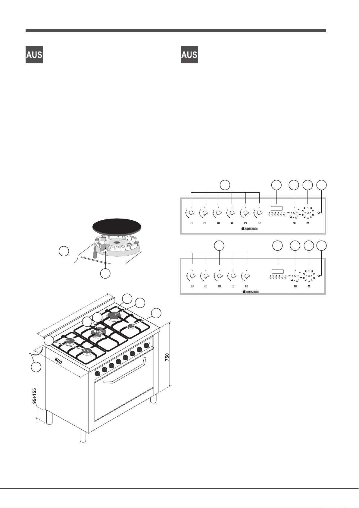
Overall view
1 AUXLIARY gas burner
2 SEMI-RAPID gas burner
3 RAPID gas burner
4 TRIPLE RING gas burner
5 DC-DR gas burner
6 Hob grid
7 STABILING CHAIN (30 cm long)
8 SAFETY DEVICE - Activates if the ame accidentally
goes out (spills, drafts, etc.), interrupting the supply of
gas to the burner.
9 IGNITOR for Gas BURNERS
8
Control panel
10 Control knobs for GAS BURNERS
11 TIMER
12 ELECTRIC OVEN THERMOSTAT KNOB
(temperature selection)
13 ELECTRIC OVEN SELECTOR KNOB
(cooking mode selection)
14 Electric heating element INDICATOR LIGHT
10
CP 059 MD (X) AUS S
10
11111212131314
14
9
6
3
800-900
2
7
5
4
1
CP 859 MT (X) AUS S
3
Page 4
AUS
Installation
! Before placing your new appliance into operation please
read these operating instructions carefully. It contains
important information concerning the safe installation and
operation of the appliance.
! Please keep these operating instructions for future
reference. Make sure that the instructions are kept with the
appliance if it is sold, given away or moved.
! The appliance must be installed by a qualied professional
in accordance with the instructions provided.
! Any necessary adjustment or maintenance must be
performed after the cooker has been disconnected from
the electricity supply.
Room ventilation
The appliance may only be installed in permanentlyventilated rooms, according to current national legislation.
The room in which the appliance is installed must be
ventilated adequately in order to provide as much air as is
needed by the normal gas combustion process (the ow of
air must not be lower than 2 m3/h per kW of installed power).
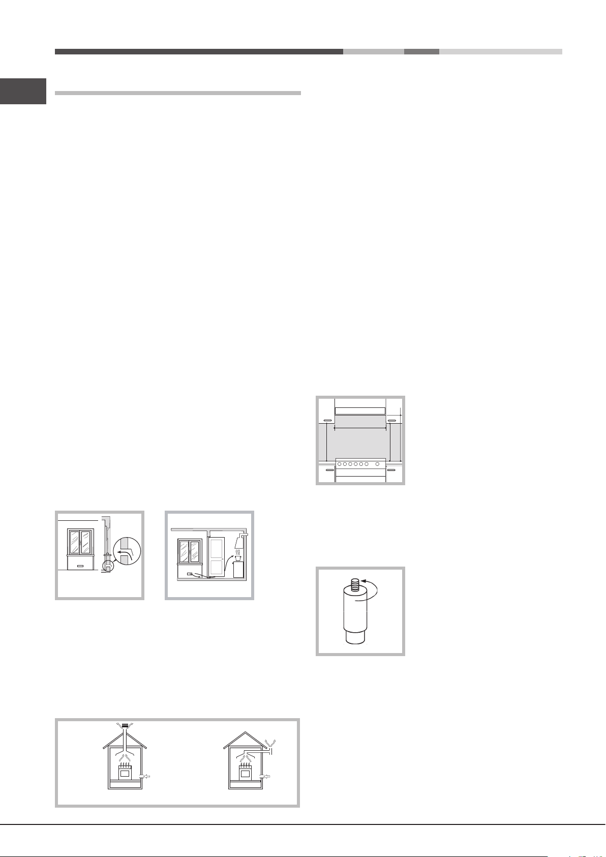
The air inlets, protected by grilles, should have a duct
with an inner cross section of at least 100 cm2 and should
be positioned so that they are not liable to even partial
obstruction (see gure A).
These inlets should be enlarged by 100% - with a minimum of
200 cm2 - whenever the surface of the hob is not equipped with
a ame failure safety device. When the ow of air is provided in
an indirect manner from adjacent rooms (see gure B), provided
that these are not communal parts of a building, areas with
increased re hazards or bedrooms, the inlets should be tted
with a ventilation duct leading outside as described above.
Adjacent
Room
Room to be
Vented
! The liqueed petroleum gases are heavier than air and
collect by the oor, therefore all rooms containing LPG
cylinders must have openings leading outside so that any
leaked gas can escape easily.
LPG cylinders, therefore, whether partially or completely full,
must not be installed or stored in rooms or storage areas
which are below ground level (cellars, etc.). Only the cylinder
being used should be stored in the room; this should also
be kept well away from sources of heat (ovens, chimneys,
stoves) which may cause the temperature of the cylinder
to rise above 50°C.
Positioning and levelling
! The appliance may be installed alongside any cupboards
whose height does not exceed that of the hob surface.
! Make sure that the wall in contact with the back of the
appliance is made from a non-ammable, heat-resistant
material (T 90°C).
To install the appliance correctly:
• Place it in the kitchen, the dining room or the studio at
(not in the bathroom).
• If the top of the hob is higher than the cupboards, the
appliance must be installed at least 500 mm away from
them.
• If the cooker is installed
HOOD
Min. mm.
600
mm.
420
Min.
• Do not position blinds behind the cooker or less than 200
mm away from its sides.
• Any hoods must be installed in accordance with the
instructions listed in the relevant operating manual.
underneath a wall cabinet, there
must be a minimum distance of 420
mm between this cabinet and the
top of the hob.
420
700 mm. without hood
Min. mm.
This distance should be increased
min. 650 mm. with hood
min.
to 700 mm if the wall cabinets are
ammable (see gure).
A
Examples of
ventilation holes
for comburant air.
Enlarging the ventilation slot
between window and floor.
A B
! After prolonged use of the appliance, it is advisable to open
a window or increase the speed of any fans used.
Disposing of combustion fumes
The efcient disposal of combustion fumes should be
guaranteed using a hood which is connected to a safe
and efcient natural suction chimney, or using an electric
fan which begins to operate automatically every time the
appliance is switched on (see gure).
In a chimney stack or branched flue.
(exclusively for cooking appliances)
Directly to
the Outside
4
Levelling
If it is necessary to level the
appliance, screw the adjustable
feet into the places provided on
each corner of the base of the
cooker (see gure).
Electrical connection
THE APPLIANCE MUST BE EARTHED
The hob is designed to work with alternating current
at the supply voltage and frequency indicated on the
rating plate (situated under the hob or at the end of the
instruction booklet). Make sure that the local supply voltage
corresponds to the voltage indicated on the rating plate.
Page 5
Connecting the supply cable to the mains electricity
supply
For models supplied without a plug, t a standard plug,
suitable for the load indicated on the rating plate, onto the
cable and connect to a suitable socket.
To connect directly to the mains supply, a double-pole
switch with a contact separation of at least 3 mm suitable
for the load and complying with current standards and
regulations, must be tted between the appliance and the
mains supply outlet. The yellow-green earth wire must not
be interrupted by the switch. The supply cable must be in
such a position that no part of it can reach a temperature
of 50 °C above room temperature. For installation above a
built-under oven, the hob and the oven must be connected
separately to the electricity supply both for safety reasons
and for easy removal of the oven if necessary. Do not use
adapters or shunts as they could cause heating or burning.
Before connecting to the power supply, make sure that:
• the limiter valve and the domestic system can withstand
the load from the appliance (see rating plate);
• the supply system is efciently earthed according to
standards and laws in force;
• the socket or double-pole switch are easily accessible
when the appliance is installed.
Important: the wires in the mains lead are coloured in
accordance with the following code:
Green & Yellow - Earth
Blue - Neutral
Brown - Live
! Make sure that the gas supply pressure is consistent
with the values indicated in the Table of burner and nozzle
specifications (see below). This will ensure the safe
operation and durability of your appliance while maintaining
efcient energy consumption.
Gas connection using a exible rubber hose
Make sure that the hose complies with current national
legislation. The internal diameter of the hose must measure: 8
mm for a liquid gas supply;13 mm for a methane gas supply.
Once the connection has been performed, make sure that
the hose:
• Does not come into contact with any parts which reach
temperatures of over 50°C.
• Is not subject to any pulling or twisting forces and that it
is not kinked or bent.
• Does not come into contact with blades, sharp corners
or moving parts and that it is not compressed.
• Is easy to inspect along its whole length so that its
condition may be checked.
• Is shorter than 1500 mm.
• Fits rmly into place at both ends, where it will be xed
using clamps which comply with current regulations.
! If one or more of these conditions is not fullled or if the
cooker must be installed according to the conditions listed
for class 2 - subclass 1 appliances (installed between two
cupboards), the exible steel hose must be used instead
(see below).
AUS
As the colours of the wires in the mains lead may not
correspond with the coloured markings identifying the
terminals in your plug, proceed as follows:
Connect the Green & Yellow wire to terminal marked “E”
or or coloured Green or Green & Yellow.
Connect the Brown wire to the terminal marked “L” or
coloured Red.
Connect the Blue wire to the terminal marked “N” or coloured
Black.
FAILURE TO OBSERVE THE ACCIDENT-PREVENTION
REGULATIONS RELIEVES THE MANUFACTURER OF
ALL LIABILITY.
Replacing the cable
Use a rubber cable of the type H05VV-F with a cross section
of 3 x 1.5 mm².
The yellow-green earth wire must be 2 ÷ 3 cm longer than
the other wires.
Gas connection
Connection to the gas network or to the gas cylinder may be
carried out using a exible rubber or steel hose, in accordance
with current national legislation and after making sure that the
appliance is suited to the type of gas with which it will be supplied
(see the rating sticker on the cover: if this is not the case see
below). When using liquid gas from a cylinder, install a pressure
regulator which complies with current national regulations.
Connecting a exible jointless stainless steel pipe to
a threaded attachment
Make sure that the hose and gaskets comply with current
national legislation.
To begin using the hose, remove the hose holder on
the appliance (the gas supply inlet on the appliance is a
cylindrical threaded 1/2 gas male attachment).
! Perform the connection in such a way that the hose length
does not exceed a maximum of 2 metres, making sure that
the hose is not compressed and does not come into contact
with moving parts.
Checking the connection for leaks
When the installation process is complete, check the hose
ttings for leaks using a soapy solution. Never use a ame.
Adapting to different types of gas
It is possible to adapt the appliance to a type of gas other
than the default type (this is indicated on the rating label
on the cover).
Adapting the hob
Replacing the nozzles for the hob
burners:
1. Remove the hob grids and slide
the burners off their seats.
2. Unscrew the nozzles using a 7
mm socket spanner (see gure), and
replace them with nozzles suited to
the new type of gas (see Burner and
nozzle specications table).
5
Page 6

AUS
3. Replace all the components by following the above
instructions in reverse.
Replacing the nozzles on separate “double ame “
burners
1. remove the grids and slide the burners from their
housings. The burner consists of 2 separate parts (see
gure);
2. unscrew the burers with a 7 mm wrench spanner. The
internal burner has a nozzle, the external burner has
two (of the same size). Replace the nozzle with models
suited to the new type of gas (see “Table of burner and
nozzle specications”).
3. replace all the components by repeating the steps in
reverse order.
Safety Chain
! In order to prevent the appliance from overturning
accidentally, for example in case of a child climbing onto
the oven door, the safety chains MUST be installed!
The cooker is provided with safety chains that must be xed
with a screw (not supplied as accessory) on the wall behind
the appliance, at the same height as the xing point on the
appliance.
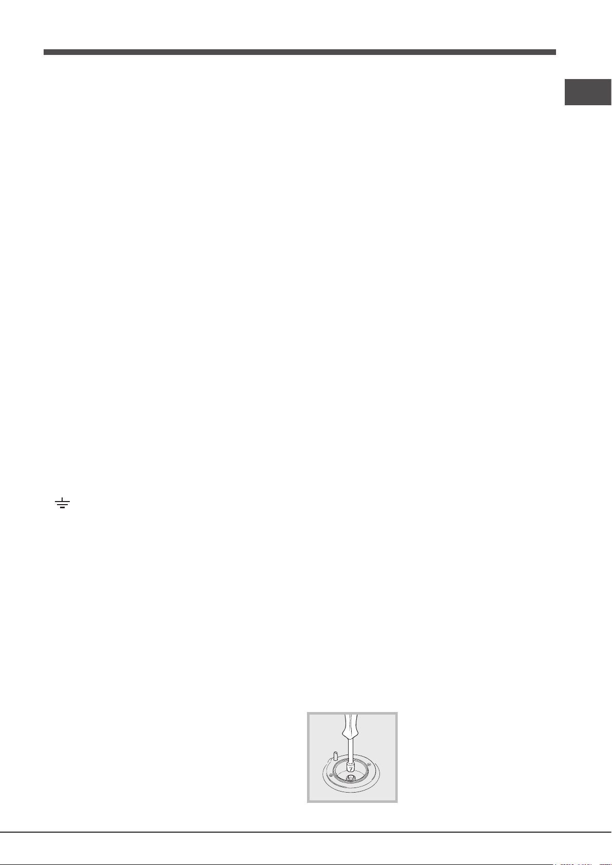
Adjusting the hob burners’ minimum setting:
1. Turn the tap to the minimum position.
2. Remove the knob and adjust the regulatory screw, which
is positioned inside or next to the tap pin, until the ame is
small but steady.
! If the appliance is connected to a liquid gas supply, the
regulatory screw must be fastened as tightly as possible.
3. While the burner is alight, quickly change the position of
the knob from minimum to maximum and vice versa several
times, checking that the ame is not extinguished.
! The hob burners do not require primary air adjustment.
! After adjusting the appliance so it may be used with a
different type of gas, replace the old rating label with a new
one which corresponds to the new type of gas (these labels
are available from Authorised Technical Assistance Centres).
! Should the gas pressure used be different (or vary slightly)
from the recommended pressure, a suitable pressure regulator
must be tted to the inlet hose in accordance with current
national regulations relating to “regulators for channelled gas”.
Make sure that the chains are xed in the back of the
cooker, as shown in the drawing, in such way to be tight
and parallel to the oor.
! When the installation process is complete, the chains must
be kept in tension!
TABLE OF CHARACTERISTICS
Oven
dimensions
HxLxP
Volume
Voltage and
frequency
Burners
ENERGY
LABEL
32,9 x 59,5 x 39,4 cm
lt. 78
230-240V~ 50Hz (see data plate)
Power supply Max 2850-3150 W
may be adapted for use with any type
of gas shown on the data plate.
Directive 2002/40/EC on the label of
electric ovens.
Standard EN 50304-60350
Energy consumption for Natural
convection – heating mode:
Convection mode
Declared energy consumption for
Forced convection Class – heating
mode:
Fan assisted.
This appliance conforms to the following
European Economic Community directives:
- 2006/95/EEC dated 12/12/06 (Low
Voltage) and subsequent amendments
- 2004/108/EEC dated 15/12/04
Electromagnetic Compatibility) and
subsequent amendments
- 93/68/EEC dated 22/07/93 and
subsequent amendments.
- 2009/142/EEC dated 30/11/09 (Gas) and
subsequent amendments.
- 2012/19/EEC and subsequent
amendments.
6
Page 7

Table of burner and nozzle specications
AUS
NATURAL PROPANE
Injector
Diameter
MJ/H Gas
Pressure
Injector
Diameter
MJ/H Gas
Pressure
57.20.5157.0x20.15.5152.1x2renruB koW retuO
57.25.305.00.13.308.0renruB koW rennI
57.20.5150.10.10.5157.1renrub sag gnir elpirT
57.20.908.00.13.892.1renruB egraL
57.25.546.00.10.601.1renruB muideM
57.25.305.00.13.308.0renruB llamS
0.244.24)SUA DM 950 PC rof ylno( CGHN latoT
5.836.83)SUA TM 958 PC rof ylno( CGHN latoT
* At 15°C and 1013 mbar - dry gas
Propane G31 H.s. = 50.37 MJ/Kg
Butane G30 H.s. = 49.47 MJ/Kg
Methane G20 H.s. = 37.78 MJ/m
3
7
Page 8

AUS
Start-up and use
Using the hob
Lighting the burners
For each BURNER knob there is a complete ring showing
the strength of the ame for the relevant burner.
To light one of the burners on the hob:
1. Bring a ame or gas lighter close to the burner.
2. Press the BURNER knob and turn it in an anticlockwise
direction so that it is pointing to the maximum ame setting
.
3. Adjust the intensity of the ame to the desired level by
turning the BURNER knob in an anticlockwise direction.
This may be the minimum setting , the maximum setting
or any position in between the two.
If the appliance is tted with an
electronic lighting device* (see
gure), press the BURNER knob
and turn it in an anticlockwise
direction, towards the minimum
ame setting, until the burner is lit.
The burner might be extinguished
when the knob is released. If this
occurs, repeat the process, holding
the knob down for a longer period of time.
! If the ame is accidentally extinguished, switch off the burner
and wait for at least 1 minute before attempting to relight it.
If the appliance is equipped with a ame failure safety device*,
press and hold the BURNER knob for approximately 2-3
seconds to keep the ame alight and to activate the device.
To switch the burner off, turn the knob until it reaches the
stop position ●.
The “separate double ame” burner*
This burner consists of two concentric burners which can
operate either together or separately.
Use of the double ame on the maximum setting gives a
very high power which reduces cooking times with respect
to conventional burners.
Moreover the double ame crown provides a more uniform
distribution of heat on the bottom of the pan, when using
both burners on minimum.
To ensure that the double-ame burner is used to its
full potential, never set the inside ring to minimum and
the outside ring to maximum at the same time.
Pots and pans of all sizes can be used. In the case of the
smaller pots and pans we recommend the use of only the
internal burner.
There is a separate control knob for each of the “separate
double ame” burners.
The knob marked by the symbol operates the external
burner;
The knob marked by the symbol operates the internal
burner.
To turn on one of the rings, press the relative knob in all the
way and turn it anti-clockwise to the high setting .
The burner is fitted with an electronic igniter that
automatically starts when the knob is pressed in.
Since the burner is equipped with a safety device, after
lighting the burner keep the knob pressed in for about
2-3 seconds to allow the device which keeps the ame lit
automatically to heat up.
The selected burner can be regulated using the corresponding
knob, as follows:
● Off
Maximum
Minimum
To switch off the burner, turn the knob in a clockwise
direction until it stops (when reaches the “●” position).
Practical advice on using the burners
For the burners to work in the most efcient way possible and
to save on the amount of gas consumed, it is recommended
that only pans which have a lid and a at base are used.
They should also be suited to the size of the burner.
Burner
Rapid (R)
Semi-rapid (S)
Auxiliary (A)
Triple.ring (TC)
Double flame (DCDR internal)
Double flame (DCDR external)
The hob is tted with reducing pan stands, which should only
be used on auxiliary burner “A” and on the DC-DR (inner) “B”.
A B
For the best performance of your burners, keep the following
in mind: All types of pans can be used on the burners. The
important thing is that the bottom should be completely even.
WARNING! The glass lid can
break in if it is heated up. Turn
off all the burners and the electric
plates before closing the lid.
Applies to the models with glass
cover only.
Ø Cookware Diameter (cm)
24 - 26
16 - 22
10 - 14
24 - 26
10 - 14
26 - 28
* Only available in certain models.
8
Page 9

Using the oven
WARNING ! The oven is
provided with a stop system
to extract the racks and
prevent them from coming
out of the oven (1).
As shown in the drawing,
to extract them completely,
simply lift the racks, holding
them on the front part, and
pull (2).
! Before operating the product, remove all plastic lm from
the sides of the appliance.
! The rst time you use your appliance, heat the empty
oven with its door closed at its maximum temperature for
at least half an hour. Ensure that the room is well ventilated
before switching the oven off and opening the oven door.
The appliance may emit a slightly unpleasant odour caused
by protective substances used during the manufacturing
process burning away.
MULTI-FUNCTION OVEN
The oven gives nine different heating element combinations;
so the most suitable type of cooking for each dish can
therefore be chosen, with convincing results.
By turning the selector knob “13” marked with the symbol
, different cooking functions are obtained, as shown in
the table on the right.
After having selected the cooking function, set the
thermostat knob “12” marked with the symbol to the
temperature required.
• For traditional cooking (roasts, biscuits, etc.) in
conventional mode use the function (hot above +
below). Only put the food to be cooked into the oven when
it has reached the selected temperature and preferably
use just one shelf for cooking.
FunctionSymbol Power
0) Off
1) Oven light
2) Top + Bottom heating elements
3) Bottom heating element
—
50 W
2350 W
1300 W
To provide heat only to the bottom or the top part of the
dishes, turn the selector to the position (hot below), or
(hot above).
• With the function (hot above and below + fan
assistance) traditional-type cooking (hot above and
below) is combined with fan assistancce.
• With this function “fan assisted” heat is transmitted
to the foods through pre-heated air made to circulate
inside the oven by a fan. The oven heats up very quickly
so the food to be cooked may be put into the oven as it
is switched on. Cooking is also possible simultaneously
on both shelves.
• The “fast defrosting“ function uses no heating
elements, just the oven light and the fan.
• Grill operation: a high heat output is used for grilling, so
that the surface of the food is immediately browned; this
is particularly indicated for meats which should remain
tender on the inside. To grill, turn the selector knob “13”
to the position (grill), (grill + fan).
During grilling, do not set the thermostat knob to
over 200 °C and keep the oven door closed (not even
in the monigrill mode).
Oven light
The oven light comes on automatically when the selector
knob is turned to any of its positions.
Indicator light “14”
It indicates that the oven is heating up. When the light goes
out, the required temperature has been reached inside the
oven.
When the light alternately comes on and goes out, it means
that the thermostat is working properly to maintain the oven
temperature constant.
Spit - Rotisserie
This accessory is to be used exclusively when grilling food.
Proceed as follows: insert the meat to be cooked along the
length of the spit rod, securing it with the special adjustable
forks.
Introduce the supports “A” and “B” into the holes in the drip
tray “E”, rest the rod groove on the seat “C” and insert the
oven rack into the lowest guide of the oven; now insert the spit
rod into the relative hole, moving the groove forward into seat
“D”. Start the grill and the rotisserie by turning the thermostat
knob “13” to the position with the or symbol.
AUS
4) Minigrill heating element
5) Grill heating element
6) Grill heating element + fan
7) Top + Bottom heating elements+fan
8) Rear round heating element + fan
9) Fast defrosting
1050 W
2000 W
2050 W
2400 W
2850 W
50 W
9
Page 10

AUS
Timer (Electric oven)
The programmer makes it possible to preset the oven and
the grill in terms of:
• delay start with a preset length of time for cooking;
• immediate start with a preset length of time for cooking;
• timer.
Button functions:
: Timer with hour and minutes;
: Length of cooking time;
: End cooking time;
: Manual change;
: Change time (backwards);
: Change time (forwards).
How to Reset the Digital Clock
After the appliance has been connected to the power source
or following a power outage, the clock display will begin to
blink and read: 0:00
• Press the buttons at the same time. Then use
(within 4 seconds) the and buttons to set the exact
time.
Use the button to move the time forwards.
Use the button to move the time backwards.
The time can also be changed in the following two ways:
1. Repeat all of the foregoing steps.
2. Press the button, and then use the and buttons
to reset the time.
Manual Operation Mode for the Oven
After the time has been set, the programmer is automatically
set to manual mode.
Note: Press the button to return the oven to manual
mode after every “Automatic” cooking session.
Delayed Start Time with Preset Cooking Length
The length and the end cooking times must be set. Let us
suppose that the display shows 10:00.
1. Turn the oven control knob to the cooking setting and
temperature desired (example: convection oven at 200°C).
2. Press the and the use (within 4 seconds) the and
buttons to set the length of the cooking time. Let us
suppose that 30 minutes was set for the length of the
cooking time. In this case, the display will show:
When “auto” is lighted, it indicates that the length and end
cooking time have been preset to operate in automatic
mode. At this point, the oven will turn on automatically
at 12:30 in order to nish the cooking session within 30
minutes. When the oven is on, the symbol (cooking
pot) will appear on the display for the entire length of the
cooking process. The button can be pressed at any
time to display the setting for the length of the cooking
time, while the button can be pressed to display the
end cooking time.
At the end of the cooking time, an acoustic signal will
sound. Press any button it turn it off (except the and
buttons).
Immediate Start Time with Preset Cooking Length
When only the length of the cooking time is set (points 1 and
2 of the paragraph entitled, “Delayed Start Time with Preset
Cooking Length”), the cooking session starts immediately.
Cancelling a Preset Cooking Time
Press the button, and use the button to set the time to:
Then press the manual cooking mode button .
Timer Feature
The timer can be used to count down from a given length
of time. This feature does not control when the oven comes
on or turns off, but, rather, it only emits an acoustic signal
when the preset time has run out.
Press the button, and the display will read:
Then use the and buttons to set the desired time.
Release the button, and the timer will start at that second.
The display will show the current time.
At the end of the preset time, an acoustic signal will sound,
which can be turned off by pressing any button (except the
and buttons), and the symbol will turn off.
Release the button, and within 4 seconds, the current time
will reappear with the symbol and “auto.”
3. Press the button, and then use the and buttons
to set the end cooking time. Let us suppose that it is 13:00
4. Release the button and the display will show the current
time within 4 seconds:
10
Changing and Cancelling Settings
• The settings can be changed at any time by pressing the
corresponding button and using the or button.
• When the length setting for the cooking time is cancelled,
the end cooking time setting is also cancelled, and vice
versa.
• When in automatic cooking mode, the appliance will not
accept end cooking times prior to the start cooking time
proposed by the appliance itself.
Buzzer volume control
Once you have made and conrmed the clock settings, use
button to adjust the volume of the alarm buzzer.
Page 11

Troubleshooting
CONVENTIONAL oven cooking
GRILLING
It may occur that the appliance does not function or does
not function properly. Before calling customer services for
assistance, let’s see what can be done.
First of all, check to see that there are no interruptions in
the gas and electrical supplies, and, in particular, that the
gas valves for the mains are open.
The burner does not light or the ame is not uniform
around the burner.
Check to make sure that:
• The gas holes on the burner are not clogged;
• All the removable parts that make up the burner are
mounted correctly;
• There are no draughts around the cooking surface.
The ame does not stay on
Check to make sure that:
• You press the knob all the way in;
• You keep the knob pressed in long enough to activate
the safety device.
• The gas holes are not clogged in the area corresponding
to the safety device.
The burner does not remain on when set to “Low”.
Check to make sure that:
• The gas holes are not clogged.
• There are no draughts near the cooking surface.
• The minimum has been adjusted correctly (see the
section entitled, “Adjusting the low ame”).
The cookware is not stable.
Check to make sure that:
• The bottom of the cookware is perfectly at.
• The cookware is centered correctly on the burner.
AUS
Type of dish
Pastries and cakes
Fruit pie
Meringues
Sponge cake
Angel cake
Madeira cake
Chocolate cake
Flat sweet loaf
Puffs
Flaky pastry biscuits
Mille feuilles
Short crust pastry
Temperature
°C
130
130
150
160
160
170
170
200
200
200
200
Type of dish
Chops (0.5 kg)
Saussages
Grilled chicken (1 kg)
Veal on the spit (0.6 kg)
Chicken on the spit (1 kg)
Cooking time
(minutes)
60-70
30-40
20-30
40-50
40-50
30-40
40-50
15-20
15-20
15-20
15-20
Cooking time
(minutes)
60
15
60
60
60
Type of dish
Meat
Turkey (4-8 kg)
Goose (4-5 kg)
Duck (2-4 kg)
Capon (2½-3 kg)
Braised beef (1-1½ kg)
Leg of lamb
Roast hare (2 kg)
Roast pheasant
Chicken (1-1½ kg)
Fish
Position of shelf
3rd guide rail
2nd guide rail
2st guide rail
-
-
Temperature
Cooking time
°C
160
160
170
170
160
160
160
160
170
200
15-25 minutes
The 1st guide rail is
understood as being
the lowest position.
(hours)
3-4½
4-4½
1½-2½
2-2½
3-3½
1-1½
1-1½
1-1½
1-1½
11
Page 12

AUS
FAN ASSISTED cooking
Type of dish
Cakes
* With beaten mix, in mould
* With beaten mix, without mould
Short pastry, flan base
Short pastry with wet filling
Short pastry with dry filling
* With natural leavened mix
Small cakes
Meat
Roasts under the grill
Veal
Beef
English roast beef
Pork
Chicken
Roasts on a tray
Veal
Beef
Pork
Chicken
Turkey slices
Duck
Casseroles
Beef casserole
Veal casserole
Fish
Fillets, steaks, cod, hake, sole
Mackerel, turbot, salmon
Oysters
Guide rail no.
from bottom
1-3
1-3-4
1-3-4
1-3
1-3-4
1-3
1-3-4
2
2
2
2
2
1-3
1-3
1-3
1-3
1-3
1-3
1
1
1-3
1.3
1-3
Quantity
kg.
1
1
0.5
1.5
1
1
0.5
1
1
1
1
1-1.5
1
1
1
1-1.5
1.5
1-1.5
1
1
1
1
Temperature
°C
175
175
175
175
175
175
160
180
180
220
180
200
160
160
160
180
180
180
175
175
180
180
180
Time
(minutes)
60
50
30
70
45
50
30
60
70
50
70
70
80
90
90
90
120
120
120
110
30
45
20
Timbales
Baked pasta dish
Vegetable pudding
* Sweet and savoury soufflés
* Pizzas and savoury rolls
Toasted sandwiches
Defrosting
Ready-to-eat meals
Meat
Meat
Meat
1-3
1-3
1-3
1-3-4
1-3-4
1-3
1-3
1-3
1-3
2
2
0.75
0.5
0.5
1
0.5
0.75
1
185
185
180
200
190
200
50
50
50
60
50
50
30
15
45
50
70
110
Cooking times may vary according to the nature of the foods, their homogeneity and their volume. When cooking a certain
food for the rst time, it is advisable to choose the lowest values in the cooking time range given in the table and then
increase them if necessary.
Notes:
1) Cooking times do not include oven pre-heating, except for those marked with an asterisk.
2) The indication given in the table for the guide rails is the one that should preferably be used in the event of cooking
on more than one level.
3) The indicated times refer to cooking on one shelf only; for cooking on more than one level, increase the time by 5 ÷
10 minutes.
4) For roast beef, veal, pork and turkey, on the bone or rolled, increase the times by 20 minutes.
12
Page 13

Precautions and tips
! This appliance has been designed and manufactured
in compliance with international safety standards. The
following warnings are provided for safety reasons and
must be read carefully.
General safety
• The instruction booklet accompanies a class
1(insulated) or class 2 - subclass 1 (recessed
between2 cupboards) appliance.
• These instructions are only valid for the countries
whose symbols appear in the manual and on the
serial number plate.
• The appliance was designed for domestic use inside the
home and is not intended for commercial or industrial use.
• The appliance must not be installed outdoors, even in
covered areas. It is extremely dangerous to leave the
appliance exposed to rain and storms.
• When moving or positioning the appliance, always use
the handles provided on the sides of the oven.
• Do not touch the appliance while barefoot or with wet or
damp hands and feet.
• The appliance must be used by adults only for
the preparation of food, in accordance with the
instructions provided in this booklet. Any other
use of the appliance (e.g. for heating the room)
constitutes improper use and is dangerous. The
manufacturer may not be held responsible for any
damage caused as a result of improper, incorrect
and unreasonable use of the appliance.
• Do not touch the heating elements or certain parts
of the oven door when the appliance is in use; these
parts become extremely hot. Keep children well away
from the appliance.
• Make sure that the power supply cables of other electrical
appliances do not come into contact with the hot parts of
the oven.
• The ventilation and heat dispersal openings must never
be obstructed.
• Always grip the oven door handle in the centre: the ends
may be hot.
• Always use oven gloves when placing cookware in the
oven or when removing it.
• Do not use aluminium foil to line the bottom of the oven.
• Do not place ammable materials in the oven: if the appliance
is switched on accidentally, the materials could catch re.
• Always make sure the knobs are in the “●”/“○” position
when the appliance is not in use.
• When unplugging the appliance, always pull the plug
from the mains socket; do not pull on the cable.
• Do not perform any cleaning or maintenance work without
having disconnected the appliance from the electricity mains.
• If the event of malfunctions, under no circumstances
should you attempt to perform the repairs yourself.
Contact an authorised Service Centre (see Assistance).
• Do not rest objects on the open oven door.
• Do not let children play with the appliance.
• If the cooker is placed on a pedestal, take the necessary
precautions to prevent the cooker from sliding off the
pedestal itself.
• The appliance should not be operated by people (including
children) with reduced physical, sensory or mental
capacities, by inexperienced individuals or by anyone
who is not familiar with the product. These individuals
should, at the very least, be supervised by someone who
assumes responsibility for their safety or receive preliminary
instructions relating to the operation of the appliance.
• Do not let children play with the appliance.
• The appliance is not intended to be operated by means
of an external timer or separate remote-control system.
Disposal
• When disposing of packaging material: observe local
legislation so that the packaging may be reused.
• The European Directive 2012/19/EEC on Waste
Electrical and Electronic Equipment (WEEE), requires
that old household electrical appliances must not
be disposed of in the normal unsorted municipal
waste stream. Old appliances must be collected
separately in order to optimise the recovery and
recycling of the materials they contain and reduce
the impact on human health and the environment.
The crossed out “wheeled bin” symbol on the product
reminds you of your obligation, that when you dispose
of the appliance it must be separately collected.
Consumers should contact their local authority or retailer
for information concerning the correct disposal of their
old appliance.
Respecting and conserving the environment
• You can help to reduce the peak load of the electricity
supply network companies by using the oven in the hours
between late afternoon and the early hours of the morning.
The cooking mode programming options, the “delayed
cooking” mode (see Cooking modes) and “delayed
automatic cleaning” mode (see Care and Maintenance) in
particular, enable the user to organise their time efciently.
• Always keep the oven door closed when using the
BARBECUE and GRATIN modes: This will achieve
improved results while saving energy (approximately 10%).
• Regularly check the door seals and wipe clean to ensure
they are free of debris so that they stick properly to the
door and do not allow heat to disperse.
Maintenance and care
Important: The appliance should be disconnected from
the mains supply before starting cleaning operations.
To ensure a long life cycle for the appliance, it is essential
to carry out a thorough general clean frequently, while
observing the following instructions:
Inside the oven door:
Clean the surface with a cloth moistened with hot water and
non abrasive liquid detergent, then rinse and dry thoroughly.
AUS
13
Page 14

AUS
Inside the oven: *
• The inside of your oven is coated with a special self-
cleaning microporous enamel glaze which, at a normal
cooking temperature of between 200 and 300°C, oxidises
and completely eliminates all grease spots or other
substances that inevitably attack the inner walls of the
oven. This way, cleaning is kept right down to a minimum:
as a matter of fact, you just need to rub the surfaces of the
oven with a wet cloth regularly, after cooking, to remove
the thin layer of ash that may have been deposited during
cooking, in order to maintain the self-cleaning property
of the oven intact.
• After cooking where liquid has overowed or when the dirt
has not been eliminated completely (for example when
grilling food, and the temperatures reached are not high
enough for the full self-cleaning action of the enamel to
be performed), we recommend you leave the oven on
at maximum temperature so that all grease residue and
the like are eliminated.
• If, after long-term use, you nd evident grease stains
deposited on the self-cleaning oven walls, probably due to
your failing to follow the above maintenance advice, clean
the surfaces thoroughly with hot water and a soft cloth (do
not use any detergents), then rinse and dry thoroughly.
• Do not remove any dry caked-on grease using sharp
objects, as these could etch the self-cleaning coating.
• If the self-cleaning surfaces inside the oven are damaged
or worn, due to incorrect or poor maintenance or after
many years of use, you can request a kit of self-cleaning
panels to line the inside of the oven. To order these, just
contact an authorised Service Centre.
Greasing the taps
As time passes, a tap may lock or become difcult to turn.
In this case it will be necessary to clean inside and replace
the grease. This procedure must be performed by a
technician authorized by the manufacturer.
Disassembling/assembling the oven door
To make it easier to clean the inside of your oven, the oven
door can be removed, by proceeding as follows:
• Open the door completely and lift the 2 levers “B”;
• Now, shutting the door slightly, you can lift it out by pulling
out the hooks “A” as shown in gure.
To reassemble the door:
• With the door in a vertical position, insert the two hooks
“A” into the slots;
• Ensure that seat “D” is hooked perfectly onto the edge of the
slot (move the oven door backwards and forward slightly);
• Keep the oven door open fully, unhook the 2 levers “B”
downwards and then shut the door again.
Oven exterior:
• Only clean the appliance when the oven is cold.
• The steel parts and especially the areas with the screen-
printed symbols should not be cleaned with solvents or
abrasive detergents. It is advisable to use only a damp
cloth with lukewarm water and washing up liquid.
Stainless steel may remain stained if in long-term contact
with very calcareous water or aggressive detergents
(containing phosphorus).
It is therefore always necessary to rinse and dry all
surfaces thoroughly after cleaning.
Important: cleaning operations must be made
horizontally, in the direction of the steel glazing.
• After cleaning, any treatments to polish the surfaces may
be performed: only use specic products for stainless steel.
Important: do not use abrasive powders, aggressive
detergents or acidic substances for cleaning.
Hob:
• The removable parts of the burners on the hob should
be washed frequently with warm water and soap, making
sure to remove any caked-on substances. Check that the
gas outlet slits are not clogged. Dry the burners carefully
before using them again.
• Clean the end part of the automatic glow plug ignitors of
the hob and gas oven frequently.
Replacing the oven light bulb
Make sure that the appliance
is disconnected from the
electricity supply.
Unscrew the glass
protective cover from inside
the oven, unscrew the
lightbulb and replace it with
an identical one suitable for
high temperatures (300°C)
and with the following
characteristics:
- Voltage 230 V
- Wattage 15 W
- Type E 14.
! Do not use the oven lamp as/for ambient lighting.
* Only available in certain models.
14
Page 15

AUS
15
Page 16

AUS
195104088.01
11/2012 - XEROX FABRIANO
16
 Loading...