

Page 1
A
B
C
E
Congratualtions on choosing an Ariston appliance, which you will find is dependable and easy to use . W e recommend
that you read this manual for best performance and to extend the life of your appliance . Thank you.
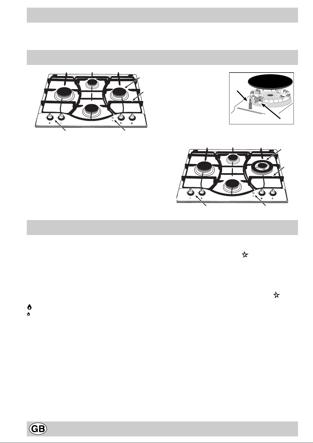
Close-up View
A
B
C
A. Gas Burners
B. Support Grid for Cookware
C. Control Knobs for Gas Burners
D. Ignitor for Gas Burners (only on certain models)
E. Ignition Button for Gas Burners (only on certain
models)
F. Safety Device (only on certain models) - Activates if
the flame accidentally goes out (spills, drafts, etc.),
interrupting the delivery of gas to the burner.
E
How T o Use Y our Appliance
F
D
The position of the corresponding gas burner or electric
hot plate (if present) is indicated on each control knob.
Gas Burners
The burners differ in size and power. Choose the most
appropriate one for the diameter of the cookware being
used.
The burner can be regulated with the corresonding control
knob by using one of the following settings:
• Off
High
Low
T o turn on one of the b urners, place a lighted match or
lighter near the burner, press the knob all the way in and
turn in the counter-clockwise direction to the "High" setting.
On those models fitted with a safety device (F), the
knob must be pressed in for about 6 seconds until the
device that keeps the flame lighted w arms up .
On those models fitted with an ignitor (D), the "E"
ignition button, identified by the symbol, must first be
pressed and then the corresponding knob pushed all the
way in and turned in the counter-clockwise direction to
the "High" setting.
Some models are equipped with an ignition switch
incorporated into the control knob. If this is the case, the
ignitor (D) is present, but not the "E" switch (the symbol
is located near each knob).
T o light a b urner, simply press the corresponding knob all
the way in and then turn it in the counter-clockwise
direction to the "High" setting, keeping it pressed in until
the burner lights.
Caution: If the burner accidently goes out, turn off the
gas with the control knob and try to light it again after
waiting at least 1 minute.
To turn off a burner, turn the knob in the clockwise
direction until it stops (it should be on the “•” setting).
2
Page 2
How to Keep Your Cooktop in Shape
Before cleaning or performing maintenance on your
appliance, disconnect it from the electrical power supply.
To extend the life of the cooktop, it is absolutely
indispensable that it be cleaned carefully and
thoroughly on a frequent basis, keeping in mind the
following:
• Do not use steam equipment to clean the appliance.
• The enameled parts and the glass top, if present, must
be washed with warm water without using abrasive
powders or corrosive substances which could ruin
them;
• The removable parts of the burners should be washed
frequently with warm water and soap, making sure to
remove caked-on substances;
• On cooktops with automatic ignition, the end of the
electronic ignition device must be cleaned carefully and
frequently, making sure that the gas holes are not
clogged;
Practical Advice
Practical Advise on Using the Burners
For best performance, f ollo w these general guidelines:
• Use the appropriate cookware for each burner (see
table) in order to prevent the flame from reaching the
sides of the pot or pan;
• Alwasy use cookware with a flat bottom and keep the
lid on;
• When the contents come to a boil, turn the knob to
"Low".
• Stainless steel can be stained if it remains in contact
with highly calcareous water or aggressive detergents
(containing phosphorous) for an extended period of
time. It is recommended that these parts be rinsed
thoroughly with water and then dried well. It is also a
good idea to clean up any spills.
Greasing the Taps
The taps may jam in time or they ma y become difficult to
turn. If so , the tap itself m ust be replaced.
N.B.: This operation m ust be performed by a technician
authorised by the manufacturer.
Burner ø Cookware Diameter (cm)
Fast (R) 24 – 26
Reduced Fast (RR) 22 – 24
Semi Fast (S) 16 – 20
Auxiliary (A) 10 – 14
Triple Crown (TC) 24 – 26
To identify the type of burner, refer to the designs in the
section entitled, "Burner and Nozzle Specifications".
3
Page 3

Is there a problem?
It may occur that the cooktop does not function or does
not function properly . Before calling customer service for
assistance, lets see what can be done.
First of all, check to see that there are no interruptions in
the gas and electrical supplies, and, in particular, that the
gas valves f or the mains are open.
The burner does not light or the flame is not uniform
around the burner.
Check to make sure that:
• The gas holes on the burner are not clogged;
• All of the movable parts that make up the burner are
mounted correctly;
• There are no draughts around the cooking surface.
The flame does not stay lighted on the model with
the safety device.
Check to make sure that:
• You press the knob all the way in;
• You keep the knob pressed in long enough to activate
the safety device .
• The gas holes are not clogged in the area
corresponding to the safety device.
The burner does not remain on when set to "Low".
Check to make sure that:
• The gas holes are not clogged.
• There are no draughts near the cooking surface.
• The minimum has been adjusted correctly (see the
section entitled, "Minimum Regulation").
The cookware is not stable.
Check to make sure that:
• The bottom of the cookware is perfectly flat.
• The cookware is centered correctly on the burner or
electric hot plate.
• The support grids have not been inverted.
If, despite all of these checks, the cooktop does not
function properly and problem persists, call the nearest
Merloni Elettrodomestici Customer Service Centre,
informing them of:
- The type of prob lem.
- The ab breviation used to identify the model (Mod. ...) as
indicated on the warranty.
Never call upon technicians not authorized by the
manufacturer, and refuse to accept spare parts that are
not original.
Safety Is a Good Habit to Get Into
To maintain the EFFICIENCY and SAFETY of this appliance, we recommend:
• call only the Service Centers authorized by the manufacturer
• always use original Spare Parts
• This manual is for a class 3 built-in cooktop.
• This appliance is designed for non-prof essional use in
the home and its features and technical characteristics
must not be modified.
• These instructions are only valid for the countries the
symbols for which appear on the manual and the serial
plate.
• The electrical system of this appliance is safe only when
it is correctly connected to an adequate earthing
system, as required by current safety standards.
Prevent children and the disabled from coming into
contact or having access to the following, as the y
are possible sources of danger:
- The controls and the appliance in general;
- The packaging (plastic bags, polystyrene, nails, etc.);
- The appliance, during and immediately after use given
the heat generated by its use;
- The appliance when no longer in installed (in this case,
all potentially dangerous parts must be made safe).
The following should be av oided:
- Touching the appliance with wet parts of the body;
- Using the appliance with bare feet;
- Pulling on the appliance or the power supply cord to
disconnect them from the electrical outlet;
- Improper and/or dangerous use;
- Obstructing the ventilation or heat dissipation slots;
- Allowing the power supply cord of small appliances to
come into contact with the hot parts of the cooktop;
- Exposure to atmospheric agents (rain, sun);
- Using flammable liquids nearby;
- Using adaptors, multiple outlet plugs and/or extensions;
- Using unstable or deformed cookware;
- Leaving the electric hobs on without cookware on top
of them;
- Closing the glass top (if present) while the gas burners
or electrical hot plates are still hot;
- Tr ying to install or repair the appliance without the
assistance of qualified personnel.
The assistance of qualified personnel must be called
upon in the following cases:
- Installation (in accordance with the manufacturer's
instructions);
- When in doubt about the operation of the appliance;
- Replacement of the electrical outlet becuase it is
incompatible with the plug.
Contact service centers authorized by the
manufacturer in the following cases:
- When in doubt about the condition of the appliance
after having removed the pac king;
- Damage to or replacement of the power supply cord;
- In the case of a breakdown or malfunction: ask for
original spare parts.
It is recommended that you follow the guidelines
below:
- Only use the appliance to cook food, avoiding all other
uses;
4
Page 4
- Check the condition of the appliance after it has been
unpacked;
- Disconnect the appliance from the power supply in the
event of malfunction and always before cleaning or
maintenance;
- When not in use, disconnect the appliance from the
power supply and turn off the gas valve (if present);
Installation Instructions for b uilt-in
- Always check to mak e sure that the control knobs are
on the “•”/”o” setting when the appliance is not in use;
- Cut the power supply cord after disconnecting it from
the electrical mains when you decide to no longer use
the appliance.
• The manufacturer will not be held liable for any
damages arising out of : incorrect installation or
improper, incorrect or unreasonable use ..
The following instructions are intended for the installer so
that the installation and maintenance procedures may be
followed in the most professional and expert manner
possible. Important: Disconnect the appliance from the
electrical supply before performing any maintenance
or regulation upkeep work.
Positioning the Cooktop
Important: this unit may be installed and used only in
permanently ventilated rooms in accordance with British
Standard Codes Of Practice: B.S. 6172 / B.S. 5440, P ar.
2 and B.S. 6891 Current Editions. The following
requirements must be observed:
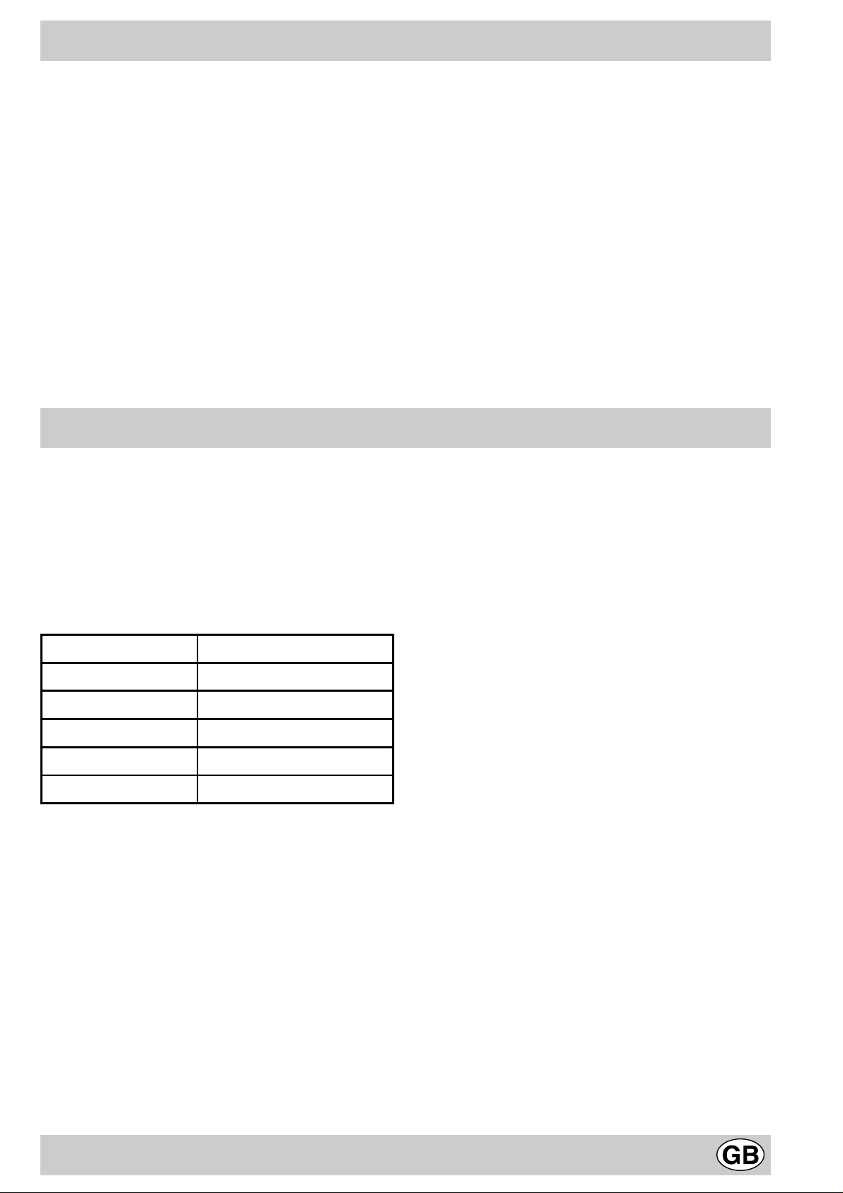
a) The room must be fitted with a ventilation system which
vents smoke and gases from combustion to the outside .
This must be done by means of a hood or electric
ventilator that turns on automatically each time the hood
is operated.
Detail A Adjacent Room to be
Room Vented
A
Examples of ventilation holes Enlarging the ventilation slot
for comburant air . between window and floor.
Fig. A Fig. B
c) Intensive and prolonged use of the appliance may ne-
cessitate supplemental ventilation, e.g. opening a window
or increasing the power of the air intake system (if
present).
d) Liquidified petroleum gases are heavier than air and, as
a result, settle downwards. Rooms in which LPG tanks
are installed must be fitted with ventilation openings to
the outside in order to allow the gas to escape in the
event of a leak. Therefore, LPG tanks, whether empty or
partially full, must not be installed or stored in rooms or
spaces below ground lev el (cellars, ect.). It is also a good
idea to keep only the tank currently being used in the
room, making sure that it is not near sources of heat
(ovens, fireplaces , stoves, etc.) that could raise the internal
temperature of the tank above 50°C .
In a chimney stack or branched flue. Directly to the Outside
(exclusively for cooking appliances)
b) The room must also allow for the influx of the air needed
for proper combustion. The flow of air for combustion
purposes must not be less than 2 m³/h per kW of installed
capacity . The supply of said air can be effected b y means
of direct influx from the outside through a duct with a
inner cross section of at least 100 cm² which must not be
able to be accidentally block ed. Those appliances which
are not fitted with a safety device to prevent the flame
from accidentally going out must have a ventilation
opening twice the size otherwise required, i.e. a minimum
of 200cm² (Fig. A). Otherwise, the room can be vented
indirectly through adjacent rooms fitted with ventilation
ducts to the outside as described above, as long as the
adjacent rooms are not shared areas, bedrooms or
present the risk of fire (Fig. B).
Installation of Built-in Cooktops
The appliance can be installed next to furniture units which
are no taller than the top of the cooker hob. The wall in
direct contact with the back panel of the cooker must be
made of non-flammable material. During operation the
back panel of the cooker could reach a temperature of
50°C above room temperature. For proper installation of
the cooker , the f ollowing precautions must be tak en:
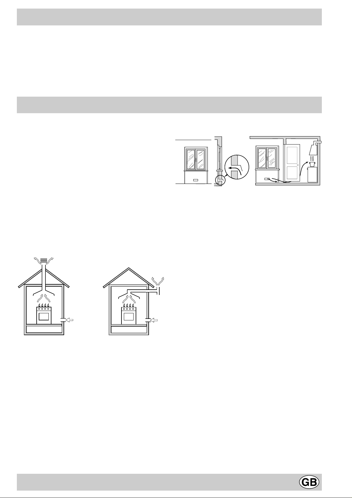
a) If the cabinet(s) located next to the cooktop are higher
than the cooktop itself, the cabinet(s) must be installed
at least 110 mm from the edge cooktop;
b) Hoods must be installed in accordance with the
instructions contained in the installation manual for the
hoods themselves, and no less than 650 mm from the
cooktop;
c) The cabinets installed next to the hood must be located
at a height of at least 420 mm from the top, (as sho wn
in Fig. C).
5
Page 5
mm.
420
Min.
HOOD
Min. mm.
600
mm. with hood
420
650
Min. mm.
min.
mm. without hood
700
min.
f) In the event the cooktop is not installed abov e a built-
in oven, a wood panel must be inserted as insulation.
This panel must be placed at least 20 mm from the
bottom of the cooktop itself.
Important: When installing the cooktop above a built-in
oven, the ov en should be placed on two wooden strips; in
the case of a joining cabinet surface, remember to leave
a space of at least 45 x 560 mm at the back.
Fig. C
d) Should the cooktop be installed directly under a
cupboard, the latter should be at least 700 mm
(millimetres) from the top, as shown in Fig. C.
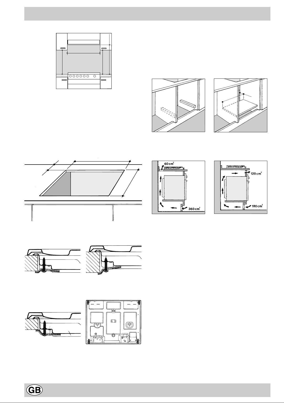
e) The dimensions of the cutout for the appliance must
be those indicated in the figure D . Clamps are pro vided
to fasten the cooktop to counters measuring from 20
to 40 mm in thickness. To fasten the cooktop securely,
it is recommended that all the clamps be used.
555 mm
55 mm
475 mm
Fig. D
Fastening Clamps - Assembly Diagram
Clamp Position f or Clamp Position f or
H=30mm top H=40mm top
Front
45 mm.
560 mm.
When installing the cooktop above a built-in ov en without
forced ventilation, ensure that there are air inlets and
outlets for ventilating the interior of the cabinet adequately .
Gas Connection for Cooktop
The cooktop should be connected to the gas supply by an
authorized installer. During installation of this product it is
essential to fit an approved gas tap to isolate the supply
from the appliance for the conv enience of any subsequent
removal or servicing. Connection of the appliance to the
gas mains or liquid gas tanks must be carried out
according to the safety standards currently in force, and
only after it is ascertained that it is suitable for the type of
gas to be used. If not, follow the instructions indicated in
the section entitled, “Adapting the Cooktop for Different
Types of Gas”. If the cooktop is to be connected to tanks
containing liquid gas, use pressure regulators that comply
with current safety standards.
Important: To insure that the appliance operates safety,
the gas is regulated correctly and your appliance lasts
over time, mak e sure that gas pressure levels comply with
the indications given in Table 1, “Nozzle and Burner
Specifications”.
Clamp Position f or
H=20mm top Back
N.B: Use the clamps contained in the "accessory kit."
Gas Connection to Non-flexible Pipe
(copper or steel)
Connection to the gas source must be done in such a way
as to not create any stress points at any part of the
appliance.
6
Page 6

The appliance is fitted with an adjustable, "L" shaped
connector and a gasket for the attachment to the gas supply .
Should this connector have to be turned, the gasket must be
replaced (supplied with the appliance).
The gas feed connector to the appliance is a threaded,
male 1/2" connector for round gas pipe.
Gas Connection to Flexible Steel Pipe
The gas feed connector to the appliance is a threaded,
male 1/2" connector for round gas pipe. Only use pipes,
tubes and gaskets that comply with current safety codes .
The maximum length of the flexible pipes must not e xceed
2000 mm. Once the connection has been made, ensure
that the flexible metal tube does not touch any moving
parts and is not crushed.
Check the Seal
Once the appliance has been installed, make sure all the
connections are properly sealed, using a soapy water
solution. Ne v er use a flame.
Electrical Connection
The cooktops fitted with a tripolar electrical supply cord
are designed to be be used with alternating current
according to the indications on the rating plate located
under the cooktop. The earthing wire can be identified by
its yellow-green colour .
In the case of installation over a b uilt-in electric oven,
the electrical connections for the cooktop and oven
should be independent, not only for safety purposes, b ut
also to facilitate removal of one or both in the future .
Electrical Connection for Gas Cooktop
Fit the supply cord with a standard plug for the demand
rate indicated on the rating plate or connect it directly to
the electrical mains. In the latter case , a single pole switch
must be placed between the appliance and the mains,
with a minimum opening between the contacts of 3 mm in
compliance with current safety codes (the earthing wire
must not be interrupted by the switch). The power supply
cord must be positioned so that it does not reach a temperature in excess of 50°C above room temperature at
any point.
Before making the actual connection, make sure that:
• The fuse and electrical system can withstand the load
required by the appliance;
• That the electrical supply system is equiped with an
efficient earth hook-up according to the norms and
regulations prescribed by law;
• That the plug or switch is easily accessible .
Important: the wires in the mains lead are coloured in
accordance with the following code:
Green & Yellow - Earth
Blue - Neutral
Brown - Live
As the colours of the wires in the mains lead may not
correspond with the coloured markings identifying the
terminals in your plug, proceed as follows:
Connect the Green & Yellow wire to the terminal marked
“E” or or coloured Green or Green & Yellow.
Connect the Brown wire to the terminal marked “L” or
coloured Red.
Connect the Blue wire to the terminal marked “N” or
coloured Black.
Adapting the Cooktop for Different Types of Gas
To adapt the cooktop to a different type of gas than that
for which it was designed, (see the sticker under the hob
or on the packaging), the burner nozzles must be changed,
as follows:
• Remove the pan supports and slide the burners out of
the cooktop.
• Unscrew the nozzles using a 7mm sock et wrench and
replace them with those for the new type of gas . (See
table 1, “Burner and Nozzle Specifications”).
• Reassemble the parts following the instructions in
reverse order.
• On completing the operation, replace the old rating label
with the one showing the new type of gas; the sticker
is availab le from our Service Centres.
If the gas pressure is different than that prescribed, a
pressure regulator must be installed at the source, in
compliance with national standards governing the use of
piped gas regulators.
Regulation of Air Supply to the Burner
The burners do not need a primary air regulator.
Minimum Regulation
Minimum regulation.
• Turn the gas valve to minimum.
• Remove the knob and turn the regulator screw
(positioned either on the side of the top or inside the
shaft) clockwise until the flame becomes small but
regular.
N.B.: In the case of liquid gas, the regulation screw must
be fully screwed in (clockwise).
• Make sure that, when the knob is turned rapidly high
to low , the flame does not go out.
• In the event of a malfunction on appliances with the
security device (thermocouple) when the gas supply
is set at minimum, increase the minimum supply lev els
using the regulator screw.
Once the adjustment has been made, apply sealing wax,
or a suitable substitute, to the old seals on the by-pass.
7
Page 7

Burners and Nozzle Specifications
Table 1 Liquid Gas Natural Gas
Burner Dia meter
(mm)
Thermal Power
kW (p.c.s.*)
Nom. Red. (1) (mm) *** ** (mm) (mm)
Fast
(Large) (R)
Reduced Fast
(RR)
Semi Fast
(Medium) (S)
Auxiliary
(Small) (A)
Triple Crown
(TC)
Supply
pressures
100 3.00 0.7 41 39 86 218 214 116 286 143 286
100 2.60 0.70 41 39 80 189 186 110 248 135 248
75 1. 65 0.4 30 28 64 120 118 96 157 105 157
55 1. 00 0.4 30 28 50 73 71 71 95 80 95
130 3.25 1.3 60 57 91 236 232 133 309 150 303
Nominal (mbar)
Minimum (mbar)
Maximum (mbar)
* At 15°C and 1013 mbar-dry gas
** Propane P.C.S. = 50.37 MJ/kg.
*** Butane P.C.S. = 49.47 MJ/kg.
By-pass
1/100
(mm)
Nozzle
1/100
Natural P.C.S. = 37.78 MJ/m
Flow*
28-30
20
35
g/h
37
25
45
Nozzle
1/100
20
17
25
Flow*
l/h
3
Nozzle
1/100
Flow*
l/h
13
6,5
18
(1) Only for appliances with the security device (Ref. F).
This appliance complies with the following European
Economic Community directives:
- 73/23/EEC of 19/02/73 (Low Voltage) and subsequent
modifications;
- 89/336/EEC of 03/05/89 (Electromagnetic
Compatibility) and subsequent modifications;
- 90/396/EEC of 29/06/90 (Gas) and subsequent
modifications;
- 93/68/EEC of 22/07/93 and subsequent modifications.
- 2002/96/EEC
The European Directive 2002/96/EC on Waste Electrical
and Electronic Equipment (WEEE), requires that old
household electrical appliances must not be disposed of
in the normal unsorted municipal waste stream. Old
appliances must be collected separately in order to
optimise the recovery and recycling of the materials they
contain and reduce the impact on human health and the
environment. The crossed out “wheeled bin” symbol on
the product reminds you of your obligation, that when y ou
dispose of the appliance it must be separately collected.
Consumers should contact their local authority or retailer
for information concerning the correct disposal of their old
appliance.
PH 640...
R
PH 640MST...
A
S
S
RR
A
TC
S
8
Page 8

Благодарим Вас за выбор изделия Ariston, надежного и простого в обращении. Для знакомства с изделием, с
A
B
порядком его оптимальной и долгосрочной эксплуатации, рекомендуем прочитать данное руководство по
эксплуатации. Благодарим за внимание
Детальный вид изделия
A
B
C
A. Газовые горелки
B. Опорные решетки для кастрюль
C. Рукоятки регуляции газовой варочной панели
D. Свеча зажигания газовый конфорок (имеется
только в некоторых моделях)
E. Кнопка зажигания газовых конфорок (имеется
только в некоторых моделях)
F. Защитное устройство (имеется только в
некоторых моделях) - Срабатывает при случайном
гашении пламени (выкипание жидкостей из
кастрюль, сквозняки и т.д.), перекрывая подачу газа
на горелку.
E
Порядок эксплуатации газовой плиты
C
F
D
E
На каждой рукоятке показано положение газовой
конфорки или электрической плиты (если имеется),
которой данная рукоятка управляет.
Газовые горелки
Конфорки имеют разную мощность и размерэ.
Выберите конфорку, наиболее соответствующую
диаметру используемой посуды.
При помощи соответствующий рукоятки можно
установить один из следующих режимов конфорки:
Выключено
Максимальный
Минимальный
Для зажигания одной из конфорок, поднесите к ней
зажженную спичку или зажигалку, нажмите до упора и
поверните против часовой стрелки соответствующую
рукоятку в положение максимального пламени.
В моделях, оснащенных устройством
безопасности F, необходимо держать рукоятку
конфорки нажатой примерно 6 секунд до тех пор, пока
не нагреется устройство, автоматически
поддерживающее горение пламени.
В моделях, оснащенных свечой зажигания D, äëÿ
зажигания нужной конфорки необходимо сначала
нажать кнопку включения E, обозначенную символом
, затем нажать до упора и повернуть против
часовой стрелки соответствующую рукоятку в
положение максимального пламени.
Некоторые модели оснащены системой зажигания,
встроенной в рукоятку. В этом случае имеется свеча
зажигания D, а не кнопка E (символ находится
рядом с каждой рукояткой).
Для включения нужной конфорки достаточно нажать
до упора соответствующую рукоятку и повернуть ее
против часовой стрелки в положение максимального
пламени, удерживая ее нажатой вплоть до зажигания
пламени.
Предупреждение: при случайном гашении пламени
конфорки поверните рукоятку управления в положение
выключено и попытайтесь вновь зажечь конфорку
только по прошествии не менее 1 минуты.
Для выключения конфорки поверните рукоятку по
часовой стрелке вплоть до гашения пламени
(положение, обозначенное символом «»).
9
Page 9

Уход за варочной панелью
Перед началом какой-либо операции по обслуживанию
или чистке отсоединить изделие от сети
электропитания.
Для длительной службы варочной панели важно
регулярно производить ее тщательную общую
чистку, учитывая следующее:
· не используйте для чистки паровые агрегаты
мойте эмалированные части и стеклянную крышку,
если имеются, теплой водой без использования
абразивных порошков и коррозийных моющих
средств, которые могут повредить такие
поверхности;
необходимо регулярно мыть съемные части
конфорок горячей водой с моющим средством,
тщательно удаляя все возможные налеты;
на варочных панелях, оснащенных автоматическим
зажиганием, следует регулярно чистить
наконечники устройств мгновенного электронного
зажигания и проверять, чтобы отверстия газовых
конфорок не были засорены;
Рекомендации по эксплуатации
на деталях из нержавеющей стали могут
образоваться пятна, если они остаются в течение
длительного времени в контакте с водой
повышенной жесткости или с агрессивными
моющими средствами (содержащими фосфор).
После чистки рекомендуется тщательно удалить
остатки моющего средства влажной тряпкой и
высушить. Кроме того следует незамедлительно
удалять возможные утечки воды.
Уход за рукоятками конфорок
Со временем рукоятки плиты могут заблокироваться
или вращаться с трудом, поэтому потребуется
произвести их внутреннюю чистку и замену всей
рукоятки.
ПРИМЕЧАНИЕ: Данная операция должна
выполняться техником, уполномоченным
производителем.
Практические советы по эксплуатации газовых
конфорок
Для максимальной отдачи следует помнить:
для каждой конфорки используйте подходящую
посуду (смотри таблицу) с тем, чтобы пламя
конфорки не выходило из-под дна посуды.
всегда используйте посуду с плоским дном и с
крышкой.
в момент закипания поверните рукоятку плиты в
положение малого пламени.
Kонфорка ш Диаметр кастрюли (см)
Быстрая
(Большая)(R)
Быстрая
сокращенная (RR)
Средняя (S) 16 20
Малая (А) 10 14
Тройная (ТС) 24 26
Для определения типа конфорки смотрите рисунки в
параграфе «Характеристики конфорок и форсунок».
24 26
22 24
10
Page 10

Что делать в случае возникновения неисправностей
Что делать, если варочная панель работает
неисправно или не работает вовсе. Перед тем как
обратиться в центр технического обслуживания,
следует самостоятельно произвести следующие
проверки.
Прежде всего следует проверить, чтобы ни в сети
электропитания, ни на газопроводе не было разрывов,
и в частности, чтобы общий газовый кран был открыт.
Конфорка не зажигается, или пламя горит
неравномерно.
Проверьте следующее:
Форсунки газовой конфорки не должны быть
засорены.
Все подвижные части конфорки дожны быть
установлены правильно.
Рядом с газовой варочной панелью не должно быть
сквозняков.
В моделях плиты, оснащенных защитным
устройством, конфорка загорается и сразу гаснет.
Проверьте следующее:
Рукоятка конфорки нажата не до упора.
Рукоятка была нажата в течение времени,
недостаточного для включения защитного
устройства.
Засорены форсунки газовой конфорки,
расположенные напротив защитного устройства.
Конфорка гаснет в положении малого пламени.
Проверьте следующее:
Засорены форсунки газовой конфорки.
Рядом с газовой варочной панелью не должно быть
сквозняков.
Неправильная регуляция малого пламени
(Смотрите параграф «Регуляция малого пламени»).
Нестабильные кастрюли
Проверьте следующее:
Дно кастрюли должно быть идеально плоским.
Кастрюля должна быть установлена по центру
газовой или электрической конфорки.
Опорные решетки на варочной панели установлены
неправильно.
Если несмотря на все проверки варочная панель не
работает, и обнаруженная неисправность не устраняется,
обратитесь в ближайший Центр технического
обслуживания Merloni Elettrodomestici, имея под рукой
следующие данные:
- описание неисправности.
- Код модели (Мод. ...) указанный в гарантийном
сертификате.
Никогда не обращайтесь к неуполномоченным
техникам и не допускайте установки неоригинальных
запасных частей.
Хорошее правило - безопасность
Для обеспечения эффективной и безопасной эксплуатации данного бытового электроприбора:
обращайтесь только в уполномоченные центры технического обслуживания
всегде требуйте установку оригинальных запасных частей
Данное техническое руководство относится к
встраиваемой варочной панели класса 3.
Данное изделие предназначается для
непрофессионального использования в домашних
условия, и его характеристики не должны изменяться.
Данные инструкции действительны только в тех странах,
обозначения которых приводятся в техническом
руководстве и на заводской табличке.
Электрическая безопасность данного изделия
гарантируется, только если оно будет правильно
подсоединено к надлежащей системе заземления в
соответствии с действующими нормативами по
безопасности.
Так как газовая варочная панель является источником
опасности, не допускать детей и инвалидов к:
- газовой варочной панели и к ее регуляциям;
- упаковочным материалам (пакетам, полистиролу,
гвоздям и т.д.);
- газовой варочной панели в процессе или сразу же после
ее эксплуатации во избежание ожегов;
- выключенной варочной панели (в данном случае
необходимо обезопасить все потенциально опасные
компоненты).
Избегайте следующих действий:
- не прикасайтесь к варочной панели мокрыми частями
òåëà:
- не пользуйтесь варочной панелью босиком;
- не тяните за провод электропитания или за саму
варочную панель для ее отсоединения от сети
электропитания;
- избегайте неуместных и опасных действий;
- не закрывайте вентиляционные отверстия или
отверстия для рассеивания тепла;
- эл. провода различных домашних электроприборов не
должны касаться горячих частей варочной панели;
- на варочную панель не должны воздействовать
атмосферные явления (дождь, солнце);
- не используйте горючие жидкости рядом с варочной
панелью;
- не используйте переходники, тройники и/или
удлинители;
- не используйте нестабильные или деформированные
кастрюли;
- не оставляйте включенными электрические конфорки
без посуды;
- не закрывайте стеклянной крышкой (если она имеется)
неостывшие газовые или электрические конфорки;
- не пытайтесь произвести установку или ремонт плиты
самостоятельно, без содействия квалифицированного
персонала.
В следующих случаях необходимо обратиться к
квалифицированному персоналу в обязательном
порядке:
- установка (в соответствии с инструкциями
производителя);
- в случае сомнений касательно исправного
функционирования варочной панели;
11
Page 11

- для замены эл. розетки в случае ее несовместимости с
эл. вилкой варочной панели.
В следующих случаях необходимо обратиться в
уполномоченные центры технического обслуживания:
- в случае сомнения касательно целостности варочной
панели после ее распаковки;
- в случае повреждения или замены провода
электропитания;
- в случае неисправности или плохого функционирования
изделия, запрашивая установку оригинальных запасных
частей.
Рекомендуемые операции:
- используйте варочную панель исключительно для
приготовления пищи, избегая ее использования в иных
целях;
- проверьте целостность варочной панели, сняв с нее
упаковку;
Монтаж встраиваемых варочных панелей
- в случае неисправного функционирования варочной
панели и перед осуществлением какой-либо операции
по ее техническому обслуживанию или чистки
необходимо отсоединить панель от сети электропитания;
- в случае простоя необходимо отсоединить варочную
панель от сети электропитания и перекрыть кран подачи
газа (если он предусмотрен);
- всегда проверяйте, чтобы рукоятки находились в
положении /o, когда изделие не используется;
- по окончании срока службы варочной панель
необходимо отрезать провод электропитания,
отсоединив его от сети электропитания.
Производитель не несет ответственность за возможный
ущерб, вызванный: неправильной установкой варочной
панель, ее ненадлежащим, неправильным или опасным
использованием.
Приведенные ниже инструкции предназначены для
квалифицированных монтажников для наиболее правильного
выполнения монтажа, регуляции и технического обслуживания с
соблюдением действующих нормативов.
Важно: перед началом какой-либо операции по регуляции,
техническому обслуживанию варочной панели и т.д. необходимо
отсоединить ее от сети электропитания.
Расположение
Важно: данное изделие может быть установлено и
использоваться только в помещениях с постоянной вентиляцией
в соответствии с положениями действующих Нормативов.
Необходимо соблюдать следующие требования:
a) В помещении должна быть предусмотрена система
дымоудаления в атмосферу в виде вытяжного зонта или
электровентилятора, автоматически включающихся каждый
раз, когда включается изделие.
В камин или в дымоход с медным покрытием
(для кухонных устройств для приготовления
ïèùè)
Непосредственно в
атмосферу
b) В помещении должна быть предусмотрена система,
обеспечивающая достаточный приток воздуха для
надлежащего горения. Расход воздуха, необходимый для
горения, должен быть не менее 2 м3/час на кВт установленной
мощности. Система притока воздуха может забирать воздух
непосредственно из атмосферы, снаружи здания через
воздуховод с проходным сечением не менее 100 см2, который
не может быть случайно засорен. Для кухонной бытовой
техники, рабочая поверхность которых не оснащена
защитным устройством на случай отсутствия пламени,
сечение вентиляционных отверстий должно быть увеличено
на 100%, с минимальным сечением 200 см2 (Рис. А). Или же
воздух для горения может поступать из прилегающих
помещений, оснащенных вентиляционным отверстием,
выходящим в атмосферу, как описано выше, при условии,
что эти помещения не являются пожароопасными или
спальнями (Рис.В).
Деталь А
A
Примеры вентиляционных
отверстий для притока воздуха
Ðèñ. À
Смежное
помещение
Увеличение расстояния между
дверью и полом.
Вентилируемое
помещение
Ðèñ. Â
c) Интенсивное, продолжительное использованием кухонной
техники может потребовать дополнительной вентиляции,
например, открытое окно или более эффективную
вентиляцию за счет повышения мощности механической
вытяжки, если она имеется.
d)Сжиженный газ пропан-бутан тяжелее воздуха и следовательно
застаивается внизу. По этой причине помещения, в которых
установлены баллоны с СНГ(сжиженным натуральным газом)
должны иметь вентиляционные отверстия, выходящие в
атмосферу, для удаления снизу возможных утечек газа.
Поэтому баллоны с СНГ должны быть опорожнены или
оставаться частично заполненными; они не должны
размещаться или храниться в помещениях или хранилищах,
расположенных в подземных помещениях(подвалах, и т.д.).
Следует держать в помещении только один рабочий баллон,
расположенный таким образом, чтобы он не подвергался
прямому воздействию источников тепла(печей, каминов и т.д.),
которые могут привести к нагреву баллона свыше50°C.
Монтаж встраиваемых варочных панелей
Варочная панель может быть установлена рядом с кухонными
элементами, высота которых не превышает рабочую поверхность
варочной панели. Стена, прилегающая к задней стенке кухонной
плиты, должна быть из невозгораемого материала. В процессе
работы кухонной плиты ее задняя стенка может достигнуть
температуры, которая на 50°C превышает температуру
помещения. Для правильного монтажа кухонной плиты необходимо
12
Page 12

соблюдать следующие меры предосторожности:
a) Кухонные элементы, расположенные рядом с кухонной
плитой, высота которых превышает уровень варочной панели,
должны находиться на расстояние не менее 110 мм от края
варочной панели.
b) Вытяжка должна быть установлена в соответствии с
руководством по эксплуатации вытяжки и в любом случае на
высоте не менее 650 мм.
c) Расположите навесные шкафы, прилегающие к вытяжке, на
высоте не менее 420 мм от рабочей поверхности кухни (Рис.
C).
HOOD
Min. mm.
600
mm.
420
Min.
420
Min. mm.
mm. with hood
650
min.
mm. without hood
700
min.
Ðèñ. Ñ
d) Если варочная панель устанавливается под навесным
шкафом, последний должен располагаться на высоте не
менее 700 мм от поверхности, как показано на Рис. С.
e) Ниша кухонного элемента должна иметь размеры, указанные
на Рис. D. Предусматриваются крепежные крюки,
позволяющие крепить варочную панель на рабочей
поверхности кухни тощиной от 20 до 40 мм. Для надежного
крепления варочной панели рекомендуется использовать все
прилагающиеся крюки.
Положение крюка для Сзади
top H=20mm
ПРИМЕЧАНИЕ: Используйте крюки из комплекта
«вспомогательные принадлежности»
f) Если варочная панель не устанавливается сверху встроенного
духового шкафа, необходимо вставить деревянную панель в
качестве изоляции. Эта панель должна быть установлена на
расстоянии не менее 20 мм от нижней части варочной панели.
Примечание: Если варочная панель устанавливается сверху
встроенного духового шкафа, рекомендуется установить духовой
шкаф на два деревянных бруска. Если в нише сплошная опорная
поверхность, в задней стенке ниши должен иметься проем не
менее 45 х 560 мм.
45 mm.
560 mm.
555 mm
55 mm
475 mm
Ðèñ. D
Схема крепления крюков
Положение крюка для Положение крюка для
рабочей поверхности рабочей поверхности H=30
ìì H=40 ìì
Спереди
Если варочная панель устанавливается сверху встроенного
духового шкафа, не оснащенного принудительной охладительной
вентиляцией, для надлежащей вентиляции внутри кухонного
элемента необходимо проделать вентиляционные отверстия для
циркуляции воздуха. Примеры возможного монтажа показаны на
рисунках ниже.
Подсоединение к газопроводу
Подсоединение изделия к газопроводу или к газовому баллону
должно осуществляться в соответствии с действующими
национальныи нормативами и только после проверки
соответствия изделия типу газа, к которому он подсоединяется.
В случае несоответствия выполните операции, описанные в
параграфе «Настройка на различные типы газа». В случае
использования сжиженного газа из баллона использовать
регуляторы давления, соответствующие действующими
национальныи нормативами .
Важно: для надежного функционирования, рационального
использования энергии и более длительного срока службы
электрического изделия проверьте, чтобы давление подачи газа
13
Page 13

соответствовало значениям, указанным в таблице1
«Характеристики газовых конфорок и форсунок».
Подсоединение при помощи твердой трубки (медной или
стальной)
Подсоединение к газопроводу не должно оказывать каких-либо
нагрузок на изделие. На подающем газопроводе изделия имеется
вращающееся колено с уплотнительной прокладкой. При
необходимости повернуть колено обязательно необходимо
заменить уплотнительную прокладку (прилагается к изделию).
Патрубок подачи газа в изделие имеет цилиндрическую наружную
резьбу 1/2 газ.
Подсоединение при помощи гибкой трубки из
нержавеющей стали со сплошными стенками с
резьбовыми соединениями.
Патрубок подачи газа в изделие имеет цилиндрическую наружную
резьбу 1/2 газ. Используйте только трубки и уплотнительные
прокладки, соответствующие действующим национальным
нормативам. Подсоединение этих трубок должно производиться
таким образом, чтобы их длина при максимальном растяжении
не превышала 2000 мм. По завершении подсоединения
проверить, чтобы металлическая гибкая трубка не касалась
подвижных частей или не была сжата.
Проверка уплотнения
по завершении подсоединения проверьте прочность уплотнения
всех патрубков при помощи мыльного раствора, но никогда не
пламенем.
Электрическое подсоединение
Варочные панели, оснащенные трехполярным проводом
электропитания, расчитаны на функционирование с переменным
током с напряжением и частотой электропитания, указанными
на заводской табличке с данными (расположенной снизу варочной
панели). Провод заземления провода электропитания
выделяется желто-зеленым цветом. В случае установки варочной
панели сверху духового шкафа, встроенного в кухонный элемент,
электрическое подсоединение варочной панели и духового
шкафа должно выполняться раздельно по причинам
безопасности, а так же для легкого съема духового шкафа.
Подсоединение провода изделия к сети электропитания
Подсоедините к проводу изделия стандартную электрическую
вилку, расчитанную на нагрузку, указанную на заводской табличке
с данными. В случае прямого подсоединения к сети
электропитания необходимо установить между электроприбором
и сетью многополюсный выключатель с минимальным
расстоянием между контактами 3 мм, расчитанный на нагрузку и
соответствующий действующим нормативам (провод заземления
не должен прерываться выключателем). Провод электропитания
должен располагаться таким образом, чтобы ни в какой точке он
не подвергался нагреванию, превышающему температуру
помещения на 50°C.
Перед осуществлением электрического подсоединения
необходимо проверить следующее:
ограничительный клапан и домашняя система должны быть
расчитаны на нагрузку изделия (смотрите заводскую табличку
с техническими данными);
Сеть электропитания должна быть оснащена надежным
заземлением согласно нормативам и указаниям
законодательства;
Электрическая розетка или многополюсный выключатель
должны быть легкодоступны без необходимости съема
варочной панели.
ПРИМЕЧАНИЕ: не используйте удлинители, переходники или
адаптеры, так как они могут вызвать перегрев или возгорание.
Подготовка к различным типам газа
Для подготовки варочной панели к типу газа, отличающемуся от
газа, на который варочная плита расчитана изначально (указан
на этикетке снизу варочной панели или на упаковке), необходимо
заменить форсунки конфорок следующим образом:
снимите с варочной панели опорные решетки и выньте
конфорки из своих гнезд.
отвинтите форсунки при помощи полого гаечного ключа 7 мм
и замените их на форсунки, расчитанные на новый тип газа
(смотрите таблицу 1 «Характеристики конфорок и форсунок»).
восстановить детали на свои места, выполняя операции в
обратном порядке.
По завершении операции замените старую этикетку
тарирования на новую, соответствующую новому типу
используемого газа. Этикетку можно заказать в наших Центрах
Технического Обслуживания.
Если давление используемого газа отличается от
предусмотренного давления (или варьирует), необходимо
установить на питающем газопроводе соответствующий
регулятор давления согласно действующим национальным
нормативам («Регуляторы для канализированных газов»).
Регуляция первичного воздуха конфорок
Конфорки не нуждаются в какой-либо регуляции первичного
воздуха.
Регуляция минимального пламени
Регуляция минимального пламени
поверните рукоятку в положение минимального пламени;
снимите рукоятку и поверните регуляционный винт,
расположенный внутри или рядом со стержнем крана, вплоть
до получения стабильного малого пламени;
ПРИМЕЧАНИЕ: в случае использования сжиженного газа
винт регуляции должен быть завинчен до упора.
проверьте, чтобы при резком повороте рукоятки из положения
максимального пламени на минимальное, конфорки не гасли.
в изделиях, оснащенных защитным устрйоством (термопара)
в случае неисправности изделия с конфорками при
минмальном повышении расхода
По завершении регуляции установите на место пломбы на
обводном газопроводе
14
Page 14

Характеристики газовых конфорок и форсунок
Таблица 1
Kонфорка Диаметр
(ìì)
Теплотворная
способность кВт
(p.c.s.*)
Байпас
1/100 (ìì)
Сжиженный газ Природный газ
Форсу-
íêà
1/100
(ìì)
Расход*
ã/÷àñ
Форсу-
íêà
1/100
(ìì)
Расход-
* ë/÷àñ
Форсу-
íêà
1/100
(ìì)
Расхо-
ä* ë/÷àñ
Номин. Сокращ. (1) *** **
Быстрая
(Большая)(R)
100 3.00 0.70 41 39 86 218 214 116 286 143 286
Быстрая
(сокращенная)
100 2.60 0.70 41 39 80 189 186 110 248 135 248
(RR)
Полубыстрая
(Средняя)(S)
75 1.65 0.40 30 28 64 120 118 96 157 105 157
Вспомогател-
ьная (Малая)
55 1.00 0.40 30 28 50 73 71 71 95 80 95
(À)
Тройная (ТС) 130 3.25 1.30 60 57 91 236 232 133 309 150 303
Давление
подачи
Номинальное (мбар)
Минимальное (мбар)
Максимальное (мбар)
28-30
20
35
37
25
45
20
17
25
13
6,5
18
* При 15°C и 1013 мбар сухой газ
** Пропан Теплотворная способность = 50,37 МДж/кг
*** Бутан Теплотворная способность = 49,47 МДж/кг
Природный газ Теплотворная способность = 37,78 МДж/м3
(1) Только для изделий, оснащенных защитным устройством против утечки газа (ссылка F).
CISPH 640... CISPH 640MST...
A
Данное изделие соответствует следующим
R
S
Директивам Европейского Сообщества:
- 73/23/CEE от 19/02/73 (Низкое напряжение) и
последующим изменениям;
S
- 89/336/CEE от 03.05.89 (Электромагнитная
совместимость) и последующим изменениям;
- 90/396/CEE от 29.06.90 (Газ) и последующим
изменениям;
- 93/68/CEE от 22.07.93 и последующим изменениям.
A
RR
TC
S
15
 Loading...