

Page 1
Operating Instructions
OVEN
GB
RS
Русский, 12English,1
CISHB 10 A.1
CISHB 10 A.1 IX
Contents
GB
Installation, 2-4
Positioning
Electrical connections
Data plate
Description of the appliance, 5
Overall view
Control panel
Start-up and use, 6
Starting the oven
Cooking modes, 7-8
Cooking modes
Practical cooking advice
Cooking advice table
Hob, 9
Type of hob
Switching on the glass ceramic hob
Practical advice on using the glass ceramic hob
Precautions and tips, 10
General safety
Disposal
Respecting and conserving the environment
Maintenance and care, 11
Switching the appliance off
Cleaning the appliance
Cleaning the oven door
Replacing the light bulb
Assistance
Page 2
543
560 mm.
45 mm.
Installation
GB
Before placing your new appliance into operation
please read these operating instructions carefully.
They contain important information for safe use, for
installation and for care of the appliance.
Please keep these operating instructions for future
reference. Pass them on to possible new owners of
the appliance.
Positioning
Keep packaging material out of the reach of
children.It can become a choking or suffocation
hazard (see Precautions and tips).
The appliance must be installed by a qualified
person in compliance with the instructions provided.
Incorrect installation may cause harm to persons,
animals or may damage property.
Fitting the appliance
Use the appropriate cabinet to ensure that the
appliance functions properly.
The panels adjacent to the oven must be made of
heat-resistant material.
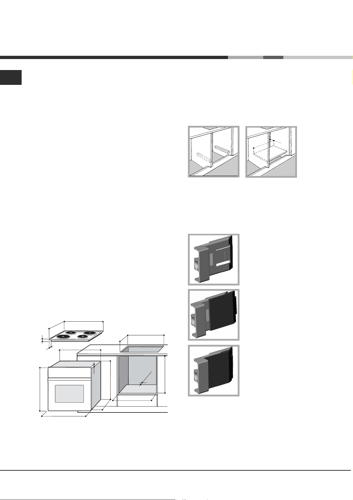
Ventilation
To ensure good ventilation, the back panel of the
cabinet must be removed. It is advisable to install the
oven so that it rests on two strips of wood, or on a
completely flat surface with an opening of at least 45 x
560 mm (see diagrams).
Centring and fastening
Position the 4 tabs on the side of the oven according
to the 4 holes of the outer frame. Adjust the tabs
according to the thickness of the cabinet side panel,
as shown below:
thickness of 20 mm: take off
the removable part of the tab
(see diagram)
Cabinets with a veneer exterior must be assembled
with glues which can withstand temperatures of up
to 100°C.
To install the oven under the counter (see
diagram) and in a kitchen unit, the cabinet must
have the following dimensions:
555
580
560
min
+4 -0
min
min
45
575-585
+4 -0
480
23
572
558
543
545
500
39
15
595
595
The appliance must not come into contact with
electrical parts once it has been installed.
The consumption indications on the data plate have
been calculated for this type of installation.
thickness of 18 mm: use the
first groove, which has already
been set in the factory (see
diagram)
thickness of 16 mm: use the
second groove (see diagram)
Secure the appliance to the cabinet by opening the
oven door and putting 4 screws into the 4 holes of the
outer frame.
All parts which ensure the safe operation of the
appliance must not be removable without the aid of a
tool.
2
Page 3
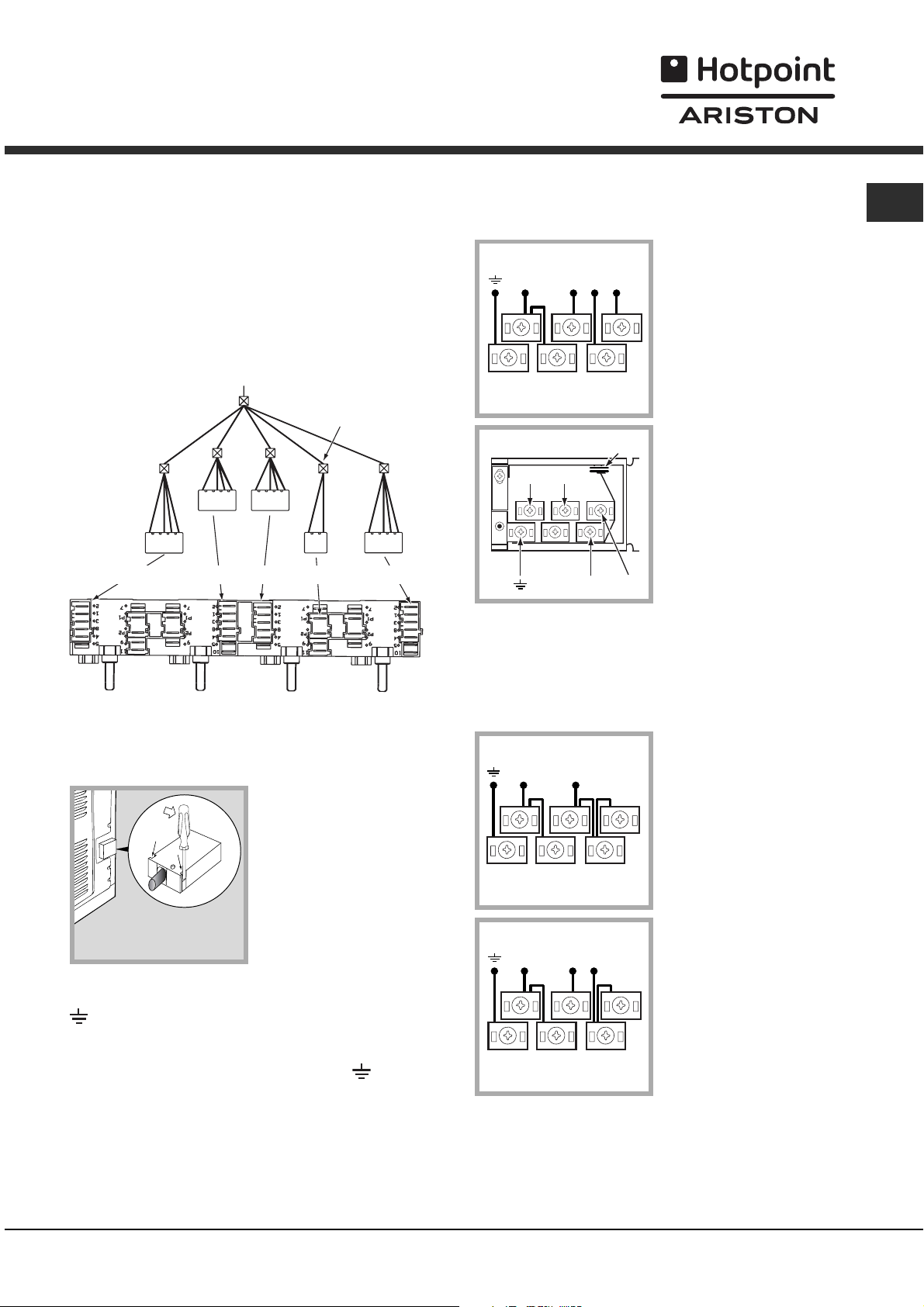
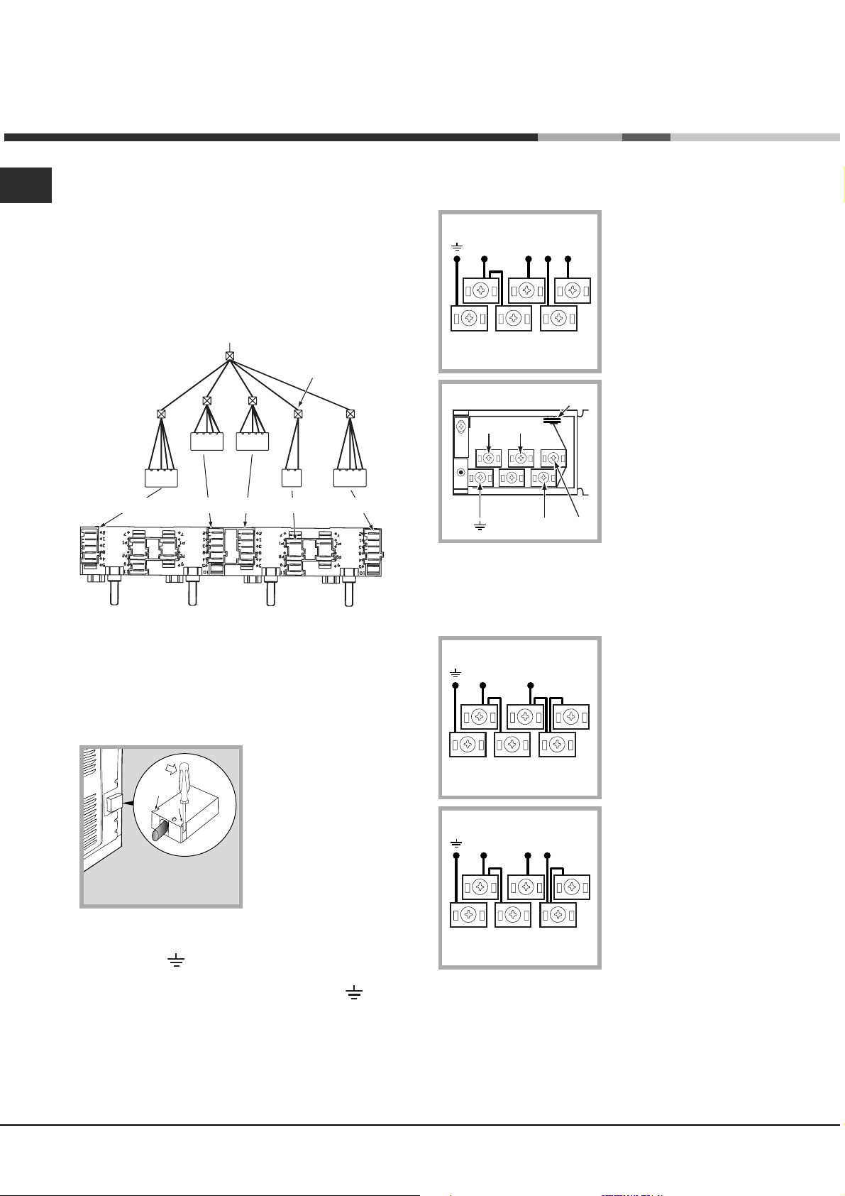
Electrical connections
NL2L3
L1
P
The cooker must be connected to the mains
electricity supply. It is designed to operate with
alternating current at the voltage and frequency
indicated on the data plate (see the following page).
The hob is connected to the cooker using a special
connector.
BUILT-IN HOB
Only on
certain models
The terminal board is designed for a 400 V threephase connection (see diagrams below).
400V 3N~H05RR-F
5x2.5 CEI-UNEL 35363
NL3L1L2
5
3
4
1
2
GB
WHITE RED
YELLOW
BLUE GREEN
BUILT-IN COOKER
Fitting the power supply cable
1. Open the terminal
board by inserting a
screwdriver into the
side tabs of the cover.
Use the screwdriver as
a lever by pushing it
down to open the cover
(see diagram).
2. Install the power supply cable by loosening the
cable clamp screw and the wire contact screws L-N-
. Connect the wires to the corresponding
terminals: the Blue wire to the terminal marked (N),
the Brown wire to the terminal marked (L) and the
Yellow Green wire to the terminal marked
.
If the electrical system has other characteristics (see
diagrams below), carry out the electrical connection
using the connection supports provided in the box
P.
230V 1N~H07RN-F 3x4
NL
5
3
4
2
CEI-UNEL 35364
1
400V 2N~H05RR-F
NL2L1
5
3
4
2
4x2.5 CEI-UNEL 35363
1
Replace the metal protection after performing all the
necessary hob connections. If the hob is removed
from its position, the red cap which was originally
protecting the red connector must be replaced.
3. Secure the power supply cable by fastening the
clamp screw.
4. Close the cover of the terminal board.
3
Page 4
GB
Connecting the supply cable to the mains
Install a standardised plug corresponding to the load
indicated on the data plate (see side).
The appliance must be directly connected to the
mains using an omnipolar circuit-breaker with a
minimum contact opening of 3 mm installed between
the appliance and the mains, suitable for the load
indicated and complying with current electrical
regulations (the earthing wire must not be interrupted
by the circuit-breaker). The supply cable must not
come into contact with surfaces with temperatures
higher than 50°C.
The installer must ensure that the correct electrical
connection has been made and that it is compliant
with safety regulations.
Before connecting to the power supply, make sure
that:
The appliance is earthed and the plug is compliant
with the law.
The socket can withstand the maximum power of
the appliance, which is indicated on the data plate
(see below).
The voltage must be in the range between the
values indicated on the data plate (see below).
The socket is compatible with the plug of the
appliance. If the socket is incompatible with the
plug, ask an authorised technician to replace it. Do
not use extension cords or multiple sockets.
Once the appliance has been installed, the power
supply cable and the electrical socket must be easily
accessible.
The cable must not be bent or compressed.
The cable must be checked regularly and replaced
by authorised technicians only (see Assistance).
The manufacturer declines any liability should
these safety meas
ures not be observed.
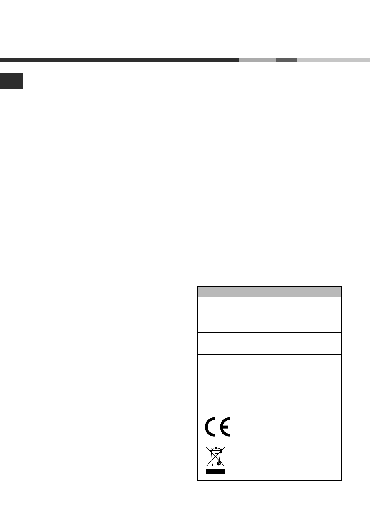
DATA PLATE
Dimensions
Volume
Electrical
connections
ENERGY LABEL
width 43.5 cm
height 32 cm
depth 43,5 cm
lt. 60
voltage: 230V/400V~ 3N 50/60Hz
maximum power absorbed 8400W
Directive 2002/40/EC on the label
of electric ovens.
Standard EN 50304
Energy consumption Class
certification Natural convection
heating mode: Traditional mode.
This appliance conforms to the
following European Economic
Community directives:
73/23/EEC of 19/02/73 (Low
Voltage) and subsequent
amendments;
- 89/336/EEC of 03/05/89
(Electromagnetic Compatibility) and
subsequent amendments;
- 93/68/EEC of 22/07/93 and
subsequent amendments.
- 2002/96/EC
4
Page 5
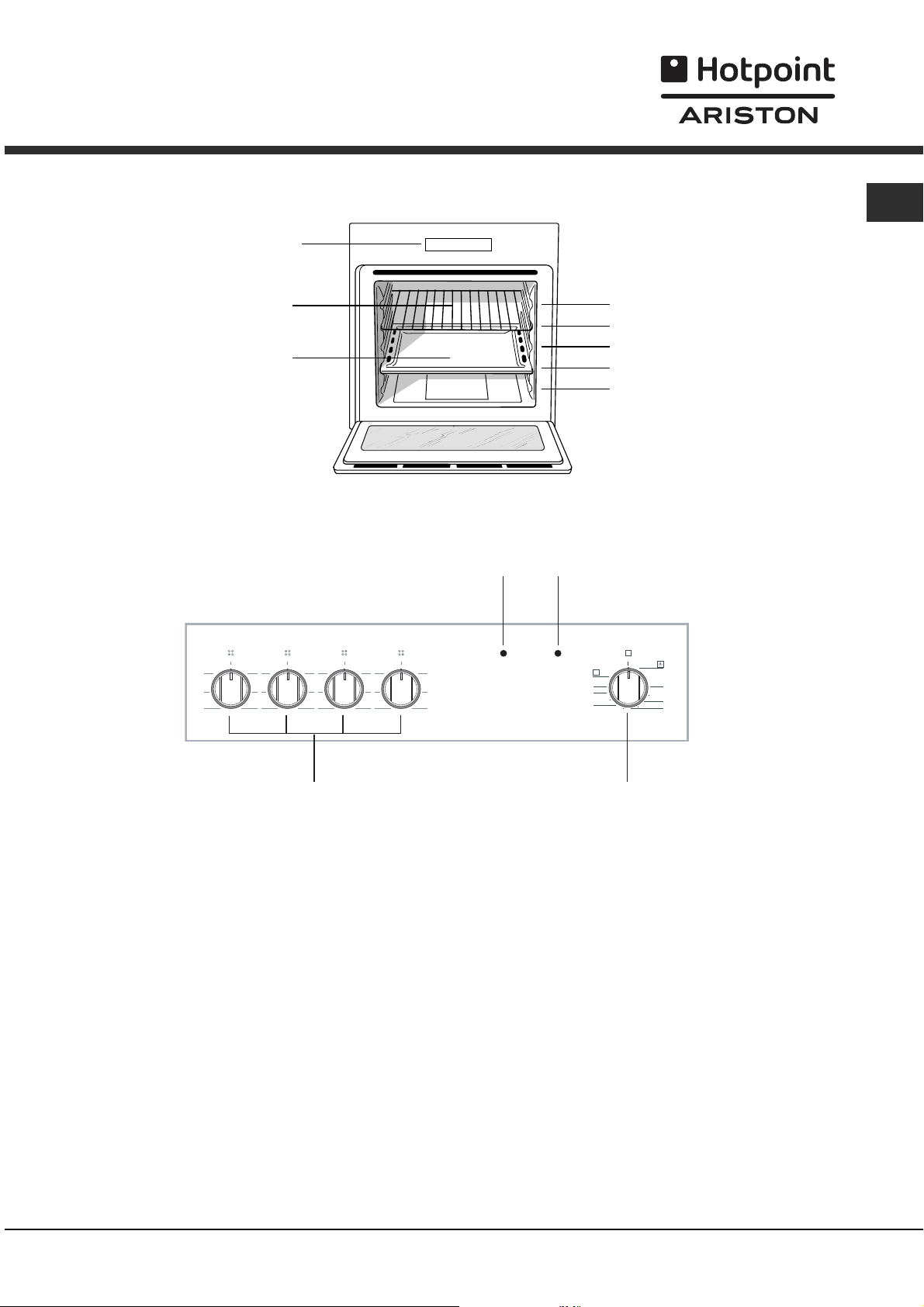
Description of the
appliance
Overall view
DRIPPING PAN
Control panel
Control panel
GRILL
HOTPLATES
indicator light
GB
GUIDES for the
sliding racks
position 5
position 4
position 3
position 2
position 1
THERMOSTAT
indicator light
0
1
25
3
0
6
1
25
3
4
0
6
1
25
3
4
6
1
25
3
4
HOTPLATES
knob
0
6
4
0
MAX
220
180
60
100
140
SELECTOR
knob
5
Page 6
Start-up and use
GB
The first time you use your appliance, heat the empty
oven with its door closed at its maximum temperature
for at least half an hour. Ensure that the room is well
ventilated before switching the oven off and opening
the oven door. The appliance may produce a slightly
unpleasant odour caused by the burning away of
protective substances used during the manufacturing
process.
Starting the oven
1. Select the desired cooking mode by turning the
SELECTOR knob.
2. See the Cooking advice table for cooking modes
and the suggested cooking temperatures (see
Cooking Modes).
3. The THERMOSTAT indicator light indicates that the
oven is heating up to the temperature set.
4. You may do the following during cooking:
- change the cooking mode by turning the SELECTOR
knob
- stop cooking by turning the SELECTOR knob to the
0 position
Cooling ventilation
In order to cool down the external temperature of the
oven, some models are fitted with a cooling fan that
blows out air between the control panel and the oven
door.
Once the cooking has been completed, the cooling
fan remains on until the oven has cooled down
sufficiently.
Oven light
When selecting
oven light goes on. It remains on when a cooking
mode is selected.
& with the SELECTOR knob the
Never put objects directly on the oven bottom to
avoid damaging the enamel coating.
Always place cookware on the rack(s) provided.
6
Page 7
Cooking modes
Cooking modes
TRADITIONAL OVEN mode
Both the top and bottom heating elements will come
on. With this traditional cooking mode, it is best to use
one cooking rack only; if more than one rack is used,
the heat will be distributed unevenly.
The oven will automatically reach the temperature set,
and the thermostat, which is controlled by the
SELECTOR knob, will keep it constant.
? TOP OVEN mode
The top heating element comes on. This mode can be
used to brown food at the end of cooking. Always
cook in this mode with the oven door closed.
Practical cooking advice
GB
In the GRILL cooking mode, place the dripping pan
in position 1 to collect cooking residues (fat and/or
grease).
GRILL
Insert the rack in position 3 or 4. Place the food in
the centre of the rack.
The top heating element is regulated by a
thermostat and may not always be on.
PIZZA
Use a light aluminium pizza pan. Place it on the
rack provided.
For a crispy crust, do not use the dripping pan
(prevents crust from forming by extending cooking
time).
If the pizza has a lot of toppings, we recommend
adding the mozzarella cheese on top of the pizza
halfway through the cooking process.
7
Page 8
GB
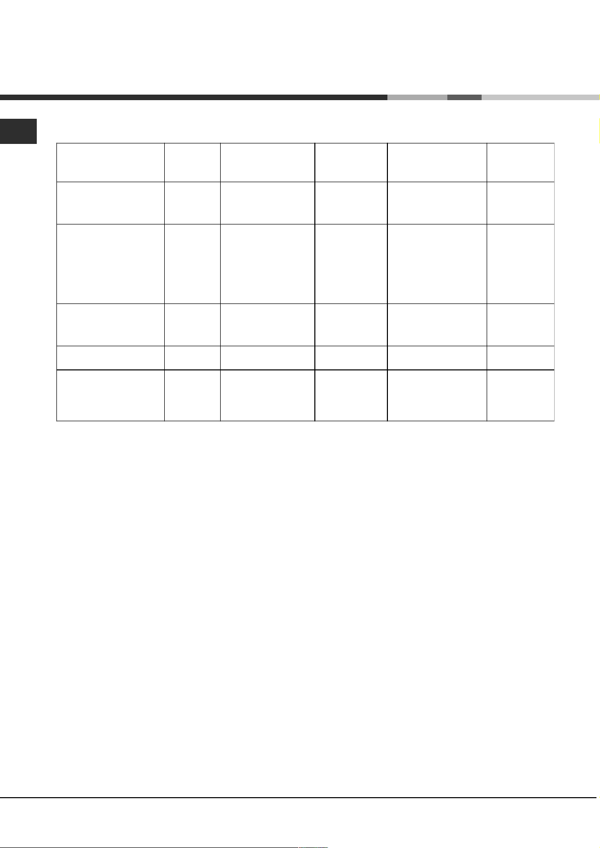
Cooking advice table
Foods
2asta
Lasagne
Cannelloni
Tagliatelle
Meat
Veal
Chicken
Turkey
Duck
Rabbit
Pork
Lamb
Fish
Mackerels
Dentex
Trout baked in foi l
2izza
Napolitan
2ies
Biscuits
Tart
Chocolate cake
Leavened cake
Weight
(in kg)
2.5
2.5
2.5
1.7
1.5
3.0
1.8
2.0
2.1
1.8
1.1
1.5
1.0
1.0 3 Max 15 30-35
0.5
1.1
1.0
1.0
Rack position
3
3
3
3
3
3
3
3
3
3
3
3
3
3
3
3
3
Pre-heating time
(min)
210
210
210
220
220
220-Max
220
220
220
220
210-230
210-230
210-230
180
180
200
200
Recommended
temperature
-
-
-
-
-
-
-
-
-
-
-
-
-
15
15
15
15
Cooking time
(minutes)
75-80
75-80
75-80
85-90
110-115
95-100
120-125
105-110
100-110
90-95
55-60
60-65
40-45
30-35
30-35
45-50
50-55
8
Page 9

Hob
Type of hob
The oven is combined with a hob that can be made up of
two types of heating elements: cast-iron electric plates
(see diagram 1) or glass ceramic hobs, which may be
traditional (see diagram 2).
A
A
C
diagram 1
A
diagram 2
A
Switching on the glass ceramic hob
Traditional cooking zones
Traditional cooking zones are made up of circular
heating elements. They turn red approximately ten
seconds after they have been turned on.
Each cooking zone is fitted with a control knob allowing
you to select from 6 different temperature settings from a
minimum of 1 to a maximum of 6.
Residual heat indicator lights (only available on
certain models)
The indicator lights (C) indicate that the temperature of
the corresponding cooking zones have exceeded 60°C,
even after the heating element has been switched off.
Recommended power levels for various types of
cooking:
Practical advice on using the glass
ceramic hob
The glue that is applied on the gaskets leaves some
traces of grease on the glass. Before using the
appliance, we recommend you eliminate these with a
special non-abrasive cleaning product. During the first
few hours of use there may be a smell of rubber which
will disappear very quickly.
To obtain the best results with your hob:
Use flat-bottomed pans to ensure that they adhere to
the cooking zone perfectly.
Always use pans with a diameter that is large enough
to cover the hotplate fully, in order to use all the
available heat.
Make sure that the bottom of the cookware is always
dry and clean to guarantee correct adherence and
long life, not only for the cooking zones but also for
the cookware itself.
Avoid using the same cookware that is used on gas
burners: the heat concentration on gas burners may
deform the base of
correctly.
the pan, causing it not to adhere
GB
Setting Normal or Fast Plate
0
Off
1
Cooking vegetables, fish
Cooking potatoes (using steam) soups,
2
chickpeas, beans.
Continuing the cooking of large quantities
3
of food, minestrone
4
For roasting (average)
5
For roasting (above average)
For browning and reaching a boil in a
6
short time.
Never leave a cooking zone on without cookware on it
because as it heats up and rapidly reaches the
maximum level, it could damage the heating
elements.
9
Page 10

Precautions and tips
GB
The appliance was designed and manufactured in
compliance with international safety standards. The
following warnings are provided for safety reasons
and must be read carefully.
General safety
The appliance was designed for domestic use
inside the home and is not intended for commercial
or industrial use.
The appliance must not be installed outdoors,
even
in covered areas. It is extremely dangerous to
leave the appliance exposed to rain and storms.
When handling the appliance, always use the
handles provided on the sides of the oven.
Do not touch the appliance with bare feet or with wet
or moist hands and feet.
The appliance must be used to cook food by adults
only and according to the instructions in this manual.
Do not touch the heating elements and parts of the
oven door when the appliance is in use; these parts
become extremely hot. Keep children well away
from the appliance.
Ensure that the power supply cable of
appliances does not come into contact with the hot
parts of the oven.
The openings used for ventilation and dispersion of
heat must never be covered.
Always grip the oven door handle in the centre: the
ends may be hot.
Always use oven gloves to place cookware in the
oven or when
Do not use aluminium foil to line the bottom of the
oven.
Do not place flammable materials in the oven: if the
appliance is switched on by mistake, it could catch fire.
Always make sure the knobs are in the l/¡
position when the appliance is not in use.
When
Never carry out any cleaning or maintenance work
In the case of a malfunction, under no circumstances
unplugging the appliance always pull the plug
from the mains socket, do not pull on the cable.
without having unplugged the plug from the mains.
should you attempt to repair the appliance yourself.
Repairs carried out by
cause injury or further malfunctioning of the
appliance. Contact a Service Centre (see
Assistance).
removing it.
inexperienced persons may
other electrical
Do not rest heavy objects on the open oven door.
The glass ceramic hob is resistant to mechanical
shocks, but it may crack (or even break) if hit with a
sharp object such as a tool.
disconnect the appliance from the electricity mains
immediately and contact a Service Centre.
Remember that the temperature of the cooking zones
remains relatively high for at least thirty minutes after
they have been switched off.
Keep any object that could melt, away from the hob,
for example plastic and aluminium objects,
products
or aluminium objects away from the hob: if you
forget them on surfaces that are still hot, they
may cause serious damage to the hob.
with a high sugar content. Keep plastic
If this happens,
or
Disposal
Observe local environmental standards when
disposing packaging material for recycling
purposes. Observe existing legislation when
disposing of the old appliance.
The European Directive 2002/96/EC on Waste
Electrical and Electronic Equipment (WEEE),
requires that old household electrical appliances
must not be disposed of in the normal unsorted
municipal waste stream. Old appliances must be
collected separately in order to optimise the
recovery and recycling of the materials they contain
and reduce the impact on human health and the
environment. The crossed out wheeled bin symbol
on the product reminds you of your obligation, that
when you dispose of the appliance it must be
separately collected.
Consumers should contact their local authority or
retailer for information concerning the correct
disposal of their old appliance.
Respecting and conserving the
environment
By using the appliance in the hours between late
afternoon and early morning, you can help reduce
the work load placed on electrical companies.
Always keep the oven door closed when using the
GRILL mode to attain best results and to save
energy (approximately 10%).
Regularly check the door seals and wipe clean to
ensure they are free of debris so that they stick
properly to the door and do not allow heat to
disperse.
10
Page 11

Maintenance and care
Switching the appliance off
Disconnect your appliance from the electricity
supply before carrying out any work on it.
Cleaning the appliance
Never use steam cleaners or pressure cleaners on
the appliance.
The stainless-steel or enamel-coated external
parts as well as the rubber seals may be cleaned
using a sponge that has been soaked in
lukewarm water and neutral soap. If these stains
are difficult to remove, use only specialised
products. After cleaning, rinse and dry
thoroughly. Do not use abrasive powders or
corrosive substances.
Ideally, the inside of the oven should be cleaned
after each use, when it is still lukewarm. Use hot
water and detergent, rinse and dry with a soft
cloth. Do not use abrasive products.
The accessories can be washed like everyday
crockery (even in your dishwasher).
3. Grip the door on the two
external sides and close it
approximately half way.
Unlock the door by pressing
on the clamps ., then pull the
F
door towards you lifting it out
of its seat (see diagram).
To replace the door, reverse
this sequence.
Inspecting the seals
Check the door seals around the oven periodically. If
the seals are damaged, please contact your nearest
After-sales Service Centre (see Assistance). We
recommend not using the oven until the seals have
been replaced.
Replacing the light bulb
To replace the oven light bulb:
GB
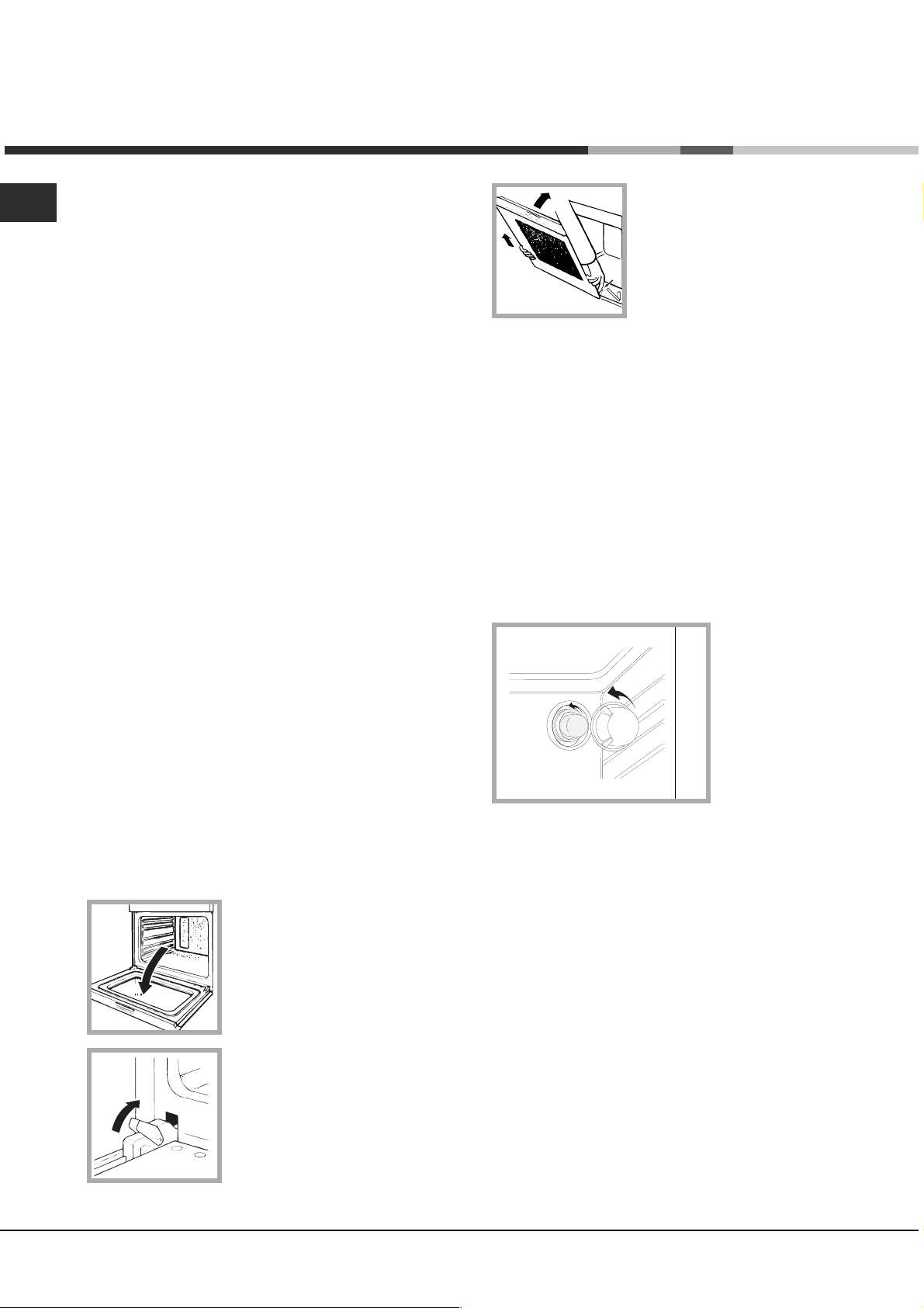
Cleaning the oven door
Clean the glass part of the oven door using a
sponge and a non-abrasive cleaning product, then
dry thoroughly with a soft cloth. Do not use rough
abrasive material or sharp metal scrapers as these
could scratch the surface and cause the glass to
crack.
To clean more thoroughly, you can remove the oven
door.
1. Open the oven door fully
(see diagram).
2. Lift up and turn the small
levers located on the two
hinges (see diagram).
1. Remove the glass cover of the lamp-holder.
2. Remove the light bulb and replace it with a similar
one: Wattage 25 W, cap E 14.
3. Replace the glass cover (see diagram).
Assistance
Never use the services of an unauthorised
technician.
Please have the following information to hand:
The type of problem encountered.
The appliance model (Mod.).
The serial number (S/N).
The latter two pieces of information can be found on
the data plate located on the appliance.
11
Page 12

Ðуково дств о ïî
экспл уатации
RS
GB
CISHB 10 A.1
CISHB 10 A.1 IX
RS
Ðусскиé, 12English,1
ДУХОВОИ ШКАФ
Содержание
Монтаж, 13-15
Ðàñположенèå
Ýëåêòðè÷åñêîå ïîäêлюченèå
Ïàñпортная таблè÷êà
Описание изделия, 16
Îáùèè âèä
Панель óправленèÿ
Включение и эксплуатация, 17
Âêлюченèå äóхового шêàôà
Программы, 18 - 19
Программы прèготовленèÿ
Ïðàêòè÷åñêèå ñоветы по прèготовленèþ
Òàáë èöà ïðèготовленèÿ
Варочная панель, 20
Моделè варочноè панелè
Âêлюченèå ñòåêëîêåðàìè÷åñêîè варочноè панелè
Ïðàêòè÷åñêèå ðåêомендацèè ïî èñпользованèþ
ñòåêëîêåðàìè÷åñêîè варочноè панелè
Предосторожности и рекомендации, 21
Îáùèе требованèÿ ê безопаñíîñòè
Óòèëèçàöèÿ
Ýêîíîìèÿ ýëåêтроэнергèè è охрана оêðóжающеè ñðåäû
Техническое обслуживание и уход, 22
Îáåñòî÷èâàíèå èçäåëèÿ
×èñòêà èçäåëèÿ
×èñòêа дверцы
Замена лампочêè
Ñåðâèñíîå îáслужиâàíèå
Page 13

543
560 mm.
45 mm.
Óñòàíîâêà
Важно сохранèть данное рóêîâîäñòâî äëÿ åãî
ïîñëåäóþùèõ êîíñóльтацèè. Â ñëóчае продажè,
передачè èçäåëèÿ èëè ïðè переезде на новое меñòî
æèòåëüñтва необходèмо проверèть, чтобы рóêîâîäñòâî
îñтавалоñü âìåñòå ñ èçäåëèем, для того чтобы его
новыè владелец мог ознаêîìèòüñÿ ñ ïðàâèëàìè
ýксплуатации è с соответствующими
ïðåäóпрежденèÿìè.
Внимательно прочèòàèòå èíñòðóêöèè: â íèх
содержатся важные сведения об установке,
эксплуатации и безопасности изделия.
Ðасположение
Не разрешаите детям èграть ñ óïàêовочнымè
матерèàëàìè. Óïàêîâêа должна быть óíèчтожена в
ñоответñòâèè ñ ïðàâèëàìè ñáîðà ìóñîðà (см.
Предосторожности и рекомендации).
Óстановêà èçäåëèÿ ïðîèçâîäèòñÿ â ñоответñòâèè ñ
даннымè èíñòðóêöèÿìè êâàëифицированнымè
ñïåöèалистамè. Неправèëüíûè монтаж èçäåëèя может
ñòàòü ïðè÷èíîè поврежденèÿ èìóùåñòâà è ïðè÷èíèòü
óщерб людям è домашнèì æèвотным.
Âстроенныи монтаж
Äëÿ îáåñпеченèÿ èñправного фóíêöèîíèрованèÿ
èçäåëèÿ êóхонныè элемент должен èìåòü
ñоответñòâóющие характеристики:
панелè êóхонных элементов, прèлегающèõ ê äóховомó
øêàôó, должны быть выполнены èз термоñòîèêого
матерèàëà;
êëåè кухонных элементов элементов иç
фанерованного дерева должен быть óñòîè÷èâûì ê
температóðå 100°C.
äëÿ âñòðàèâàíèÿ äóхового шêàôà ï
òîïîì (см. рисунок) èëè â êîëîííó íèøà êóхонного
элемента должна èìåòü ñëåäóþùèе размеры:
500
39
15
580
555
îд кухонным
560
+4 -0
480
+4 -0
Вентиëÿöèÿ
Äëÿ îáåñпеченèя надлежащеè âåíòèëÿöèè
необходèìî ñнять заднюю панель нèøè êóхонного
элемента. Ðåêомендóåòñÿ óñтановèòü äóõîâîè øêаф
на два деревянных брóñêà èëè íà ñплошное
оñнованèå ñ отверñòèåì äèаметром не менее 45 х
560 мм (см чертежи).
Öентровêà è крепление
4 êрепежных элемента ñ áîков духового шкафа
должны быть отрегóëèрованы в ñоответñòâèè ñ 4
отверñòèÿìè â ðàìå â çàâèñèìîñòè îò òîëùèíû
áîêîâîè панелè êóхонного элемента:
òîëùèна 20 мм: полноñòüþ
óäàëèòå ñúåìíóþ ÷àñòü
êрепежного элемента (ñì.
схему);
òîëùèíà 18 ìì: èñпользóèте
первыè ïàç, ñîãëàñíî óже
готовоè êîíôèãóðàöèè
ïðîèçâîäèòåëÿ (см. схему);
íà 16 ìì: èñпользóèòå
òîëùè
второè ïàç (см. схему).
RS
min
min
min
45
575-585
595
595
23
572
558
543
545
Ïîñëå âñòðàèâàíèÿ èçäåëèÿ â êóхонныè элемент
должна быть èñêлючена возможноñòü êàñàíèÿ ê
ýëåêòðè÷åñêèìè ÷àстями.
Ðàñõîä ýëåêтроэнергии, указанныè íà ïàñпортноè табли÷êå
èçäåëèя, был замерен для данного тè
па монтажа.
Äëÿ êрепленèÿ èçäåëèÿ ê êóхонномó элементó:
îòêðîèте дверцó äóхового шêàôà è çàâèíòèòå 4
øóðóпа для деревянных панелеè в 4 отверñòèÿ â
ïåðèметральноè ðàìå.
Âñå çàùèтные элементы должны быть
çàêреплены таêèм образом, чтобы èх можно было
ñíÿòü òîëüêî ïðè помощè ñïåöèального
èíñòðóмента.
Page 14
RS
NL2L3
L1
P
Электрическое подключение
Ýëåêòðè÷åñêîå ïîäñîåäèíåíèå èçäåëèÿ
выполняетьñÿ ñ êóхонноè ïëитои, расчитаннои на
переменныè òîк, с напряжением и частотои,
óêазаннымè íà ïàñпортноè òàáëè÷êе (см. следующую
страницу).
Варочная панель ñîåäèíÿåòñÿ ñ êóхонноè ïëèòîè ïðè
помощè ñïåöèального разъема.
ВСТРОЕННАЯ
ВАРОЧНАЯ ПАНЕЛЬ
Имеется только
в некоторых
моделях
Çàæèìíàÿ êîðîáêà ðàñ÷èтана на трехфазное
элеêòðîïèòàíèå 400 Â (ñì. ñõåìû íèæå).
400Â 3N~H05RR-F 5x2.5
CEI-UNEL 35363
NL3L1L2
5
3
4
1
2
БЕЛЫЙ
КРАСНЫЙ
ЖЕЛТЫЙ
СИНИЙ
ЗЕЛЕНЫЙ
ВСТРОЕННЫЙ ДУХОВОЙ ШКАФ
Ïîäсоединение ñåòåâîãî кабеля
1. Îòêðîèòå çàæèìíóþ êîðîáêó, нажав прè помощè
отвертêè íà âûñòóïû ñ áîêîâ êðûøêè: потяните и
îòêðîèòå êðûøêó (см. схему).
è ýëåêтропроводêà èìååò äðóãèå õàðàêòåðèñòèêè
Åñë
(см. схемы ниже), äëÿ ýëåêòðè÷åñêîãî ïîäñîåäèíåíèÿ
èñпользóèòå ñîåäèíèтельные перемычêè,
ðàñположенные внóòðè êîðîáêè Ð.
230Â 1N~H07RN-F 3x4 CEI-
NL
5
3
4
2
UNEL 35364
1
400Â 2N~H05RR-F 4x2.5
NL2L1
5
3
4
2
CEI-UNEL 35363
1
2. Порядоê ïîäñîåäèíåíèÿ ñетевого êабеля:
отвèíòèòå âèíò êабельного ñàëüíèêà è âèíòû
êîíòàêòîâ L-N-
è затем прèêðåïèте провода под
головêàìè âинтов, соблюдая цветовóþ ìàðêèðîâêó
Ñèíии (N) Коричневыи (L) Желто-зеленыи (
).
Óстановите на место защитную металлическую
çàãëóøêó ïîсле электричеñêого подключения
варочноè панелè. Â ñëóчае демонтажа варочноè
панелè необходèìî óñтановèòü íà ñâîå ìåñòî
êðàñíóþ çàãëóøêó íà êðàñíûè разъем.
14
3. Çàêðåïèòå ñетевоè øíóð â ñïåöèальном êабельном
ñальнике.
4. Закроите крышку зажимнои коробки.
Page 15

Ïîäсоединение ñåòåâîãî кабеля к ñåòè
ýëåêòðîïèòàíèÿ
Óñтановèòå íà ñетевоè êабель нормалèзованнóþ
øòåïñåëüíóþ âèëêó, ðàñ÷èòàííóþ íà íàãðóçêó,
óêазаннóþ íà ïàñпортноè òàáëè÷êå (см. сбоку).
 ñëóчае прямого подêлюченèÿ ê ñåòè
ýëåêòðîïèòàíèÿ ìåæäó èçäåëèåì è ñетью
необходèìî óñтановèть многополюñíûè
âûêлючатель ñ ìинимальным раññтоянием между
êîíòàêòàìè 3 ìì, ðàñ÷èтанныè íà äàííóþ íàãðóçêó è
ñоответñòâóющии деиствóþùèм нормативам
(âûêлючатель не должен размыêать провод
заземленèя). Сетевоè êабель должен быть
раñположен таêèм образом, чтобы нè â îäíîè òî÷êå
его температóра не превышала температóðó
помещенèя более чем на 50°C.
Ýëåêтромонтер неñет ответñтвенноñòü çà
ïðàâèльное подêлюченèå èçäåëèÿ ê ýëåêòðè÷åñêîè
и и за соблюдение правил безопасности.
ñåò
Перед подêлюченèåì èçäåëèÿ ê ñåòè
ýëåêòðîïèòàíèя проверьте ñëåäóþùåå:
ñетевая розетка должна быть ñîåäèíåíà ñ
заземленèåì è ñоответñтвовать норматèâàì;
ñетевая розетêа должна быть раññ÷èòàíà íà
ìàксимальнóю потребляемóю мощноñòü èçäåëèÿ,
óêазаннóþ íà ïàñпортноè òàáëè÷êå (ñì. íèæå);
напряженèå
ñåòè ýëåêòðîïèòàíèя должно
находèòüñя в пределах значенèè, óêазанных на
паñпортноè òàáëè÷êå (ñì. íèæå);
ñетевая розетêа должна быть ñîâìåñòèìà ñî
øòåïñельноè âилкои иçäåëèÿ. Â ïðîòèâíîì ñëóчае
заменèте розетêó èëè âèëêó; íå èñпользóèòå
óäëèíèòåëè èëè òðîèíèêè.
Изделèе должно быть
óñтановлено таêèм образом,
чтобы ñетевоè êабель è ñетевая розетêà áûëè ëåãêî
äîñòóïíû.
Сетевоè øíóð èçäåëèя не должен быть ñîãíóò èëè
ñæàò.
Ðåãóлярно проверяèòå ñîñòîÿíèå êабеля
ýëåêòðîïèòàíèÿ è â ñëóчае необходèìîñòè ïîðó÷èте
его заменó òîëüêî óполномоченным технèêàì (ñì.
Техническое обслуживание).
Ïðîèç
âîäèòåëü не несет ответственности çà
последствия несоблюдения перечисленных âûøå
требовании.
ПАСПОРТНАЯ ТАБЛИЧКА
Габаритные размеры
Объем
Электропитание
МАРКИРОВКА
ПОТРЕБЛЕНИЯ
ЭЛЕКТРОЭНЕРГИИ
Данное изделие
ширина 43,5 см.
высота 32 см.
глубина 43,5 см.
ë 60
напряжение 230В/400В~ 3Н
50/60Гц
макс. поглощаемая
мощность 8400 Вт
Директива 2002/40/СЕ об
этикетках электрических
духовых шкафов.
Норматив EN 50304
Расход электроэнергии
Заявление Класса
Натуральная конвекция –
режим нагрева:
Традициональная духовка.
соответствует следующим
Директивам Европейского
Сообщества: 73/23/CEE от
19/02/73 (Низкое
напряжение) с
последующими
изменениями – 89/336/СЕЕ
от 03/05/89
(Электромагнитная
совместимость) с
последующими
изменениями – 93/68/СЕЕ
от 22/07/93 с последующими
изменениями.
2002/96/CE
RS
Page 16

Îïèñàíèå èçäåëèÿ
RS
Îáùèè âèä
Ïàíåëü óïðàâëåíèÿ
Индикатор
КОНФОРОК
Индикатор
ТЕРМОСТАТА
0
1
25
3
0
6
1
25
3
4
0
6
1
25
3
4
6
1
25
3
4
Регулятор
КОНФОРОК
0
6
4
0
MAX
220
18
0
60
100
14
0
Рукоятка
ПРОГРАММЫ
16
Page 17

Âêëþ÷åíèå è
ýêñïëóàòàöèÿ
Ïðи первом вêлюченèè äóхового шêàôà
ðåêомендóåì ïðîêàëèòü åãî ïðèмерно в теченèå
÷àñà ïðè ìàксимальнои температуре с закрытои
дверцеè. Затем выêëþ÷èòå äóõîâîè øêàô, îòêðîèте
дверцó è проветрèте помещенèе. Запах, êоторыè вы
можете почóâñтвовать, вызван èñпаренèåì âåùåñòâ,
èñпользованных для предохраненèÿ äóхового шêàôà.
Включение духового øêàôà
1. Выберèòå íóæíóю программó ïðиготовления при
помощè ðóêîÿòêè ÏÐÎÃÐÀÌÌÛ.
2. Â ñïåöèальноè òàáëице приводèòñя перечень
òèïîâ ïðèготовленèÿ ñ ñоответñòâóþùèìè
ðåêомендóåìûìè температóðàìè (см. Программы).
3. Âêлюченныè èíäèêàòîð ÒÅÐМОСТАТА означает
теêóùóþ ôàçó нагрева дóõîâêè до заданноè
температóðû.
4. В процеññå ïðè
- èçìåíèть программó ïðèготовленèÿ ïðè помощè
ðóêîÿòêè ÏÐÎÃÐÀÌÌÛ;
- прервать прèготовленèе, повернóâ ðóêîÿòêó
ÏÐÎÃÐАММЫ в положенèå «0».
Íèêîãäà íå ставьте нèêàêèх предметов на дно
äóхового шêàôà, òàê êàê îíè ìîãóт повредèòü
ýìàëèрованное поêðûòèå.
готовленèÿ â ëþáîè момент можно:
Охладиòåëüíàÿ âåíòèëÿöèÿ
RS
Äëÿ ïîíèæåíèя температóðû âîêðóг работающего
дóхового шêàôà íåêоторые моделè îñнащаютñя
охладèтельным вентèлятором. Этот вентèлятор
направляет ñòðóþ âîçäóõà ìåæäó панелью
óправленèÿ è дверцеè äóхового шêàôà.
По завершенèè ïðиготовленèÿ âåíòèлятор
продолжает работать вплоть до надлежащего
охлажденèÿ äóõîâêè.
Îñâåùåíèå äóõîâîãî øêàôà
Загораетñÿ ïðè выборе & ïðи помощи рукоятки
ÏÐÎÃРАММЫ. Остаетсÿ âêлюченноè ïðè выборе
программы прèготовленèÿ.
Âсегда ñтавьте поñóäó íà ïðèлагающóþñя решетêó.
Page 18

Ïðîãðàììû
RS
Программы приготовления
Programma ТРАДИЦИÎÍÀËÜÍÀß ÄÓÕÎÂÊÀ
Âêлючаютñя два нагревательных элемента: нèæíèè è
верхнèè. Â ðåæèìå òðàäèöèонального прèготовленèÿ
ðåêомендóåòñÿ èñпользовать тольêî îäèí óровень:
прè èñпользованèè íåскольких уровнеи
ðàñпределенèе температóðû áóдет неоптèмальным.
Дóõîâêа автоматè÷åñêè нагреваетñя до заданноè
температóðû, êоторая поддержèâàåòñÿ ñòàáèëüíîè
ïîñðåäñтвом термоñòàòà, óправляемого рóêîÿòêîè
ÏÐÎÃÐÀÌÌÛ.
? Программа ÂÅÐÕÍÈÈ ÍÀÃÐÅÂÀÒÅËÜ
Âêлючаетñя верхнèè нагревательныè элемент. Эта
фóíêöèя может быть èñпользована для доводêè
готовых блюд. Готовьте блюда ñ çàêðûòîè дверцеè
äóхового шêàôà.
Ïðàêòè÷åñêèå ñîâåòû ïî
ïðèãîòîâëåíèþ
Ïðè èñпользованèè ðåæèìà ÃÐÈËÜ ïîìåñòèòå
ïðîòèâåíü íà óровень 1 для ñáîðà æидкосòåè,
выделяемого прè æàðêå (ñîê è/èëè æèð).
ÃÐÈËÜ
Óстановите решетку на уровень 3 или 4, поместите
ïðîäóêты в центр решетêè.
Íå áåñïîêîèòåñü, åñëè верхнèè элемент не
îñòàåòñÿ ïîñтоянно вêлюченным: его работа
óправляетñя термо
ПИЦЦА
Èспользóèте противень из легкого алюминия,
óñтанавлèâàÿ åãî íà ïðèлагающóþñя решетêó.
Ïðè èñпользованèè ïðîòèвеня время выпечêè
óäëèíÿåòñÿ, ÷òî çàòðóдняет полó÷åíèå õðóñòÿùåè
ïèööû.
 случае выпечêè пиццы с обильнои начинкои
ðåêомендóåòñя положèòü íà ïèööó ñыр
моццарелла в ñåðåäèне выпечêè.
ñтатом.
18
Page 19

Таблица приготовления
RS
Ïðîäóêòû
Макаронные изäåëèÿ
Ëазанья
Каннеллони
Тальятелле
Ìÿñî
Телятина
Курица
Èндейка
Óòêà
Кролик
Свинина
Áаранина
Ðûáà
Скумбрия
Зубан
Ôорель в фол ьге
Ïèööà
по-неаполитански
Âûïå÷êà
Печенье
Торт с вареньем
Øоколадный òîðò
Áисквитный òîðò
Âåñ (êã) Уровень
2,5
2,5
2,5
1,7
1,5
3,0
1,8
2,0
2,1
1,8
1,1
1,5
1,0
1,0
0,5
1,1
1,0
1,0
3
3
3
3
3
3
3
3
3
3
3
3
3
3
3
3
3
3
íàãðåâàíèÿ
220-Ìàêñ.
210-230
210-230
210-230
Âðåìÿ
(ìèí.)
210
210
210
220
220
220
220
220
220
Ìàêñ.
180
180
200
200
Рекоменäóåìàÿ
температóðà
-
-
-
-
-
-
-
-
-
-
-
-
-
15
15
15
15
15
Ïðîäîëæèò-òü
ïðèãîòîâëåíèÿ
(минуты)
75-80
75-80
75-80
85-90
110-115
95-100
120-125
105-110
100-110
90-95
55-60
60-65
40-45
30-35
30-35
30-35
45-50
50-55
Page 20

Âàðî÷íàÿ ïàíåëü
RS
Ìîäåëè âàðî÷íîè ïàíåëè
Духовои шкаф соединен с варочнои панелью,
которая может иметь два вида нагревательных
элементов: электрические чугунные (см. схему 1) или
стеклокерамические варочные панели, которые
могут быть традициональными (см. схему 2).
A
A
C
ñõåìà 1
A
ñõåìà 2
A
Включение стеклокерамическои
варочнои панели
Традициональные конфорки
Òðàäèöèональные нагревательные элементы (А)
ñîñòîÿò èç êðóãëûõ ñïèðàëåè, раскаляющèõñÿ
äîêðàñíà òîëüêо по прошеñòâèè íåñêîëüêèõ äåñÿòêîâ
ñåêóíä ïîñëå èõ âêлюченèÿ.
Каждая êонфорêà óправляетñÿ ðåãóлятором,
позволяющèм выбрать 6 разлèчных температóð îò
ìèíимального значения 1 до маêñèмального 6..
Практические рекомендации по
использованию стеклокерамическои
варочнои панели
Íà ñòåêлянноè поверхноñòè варочноè панелè ìîãóò
áûòü âèäíû ñальные ñëåäû îò êëåÿ, íàíåñенного на
проêëàäêè Перед началом эêñïëóàòàöèè èçäåëèÿ
ñëåäóåò óäàëèòü ñëåäû êëåÿ ïðè помощè
ñïåöèального неабразèвного моющего ñðåäñòâà. Â
первые чаñы работы вы можете почóâñтвовать запах
жженоè ðåçины, которыи быстро пропадает..
Äëÿ îïòèмальноè ýксплуатации варочнои панели
ñëåäóåò:
использовать посуäó ñ ïëîñêèì äíîì, èдеально
ïðèлегающèì ê зоне нагреванèÿ;
использовать кàñòðþëè ñ äíîì òàêîãî äèаметра,
чтобы полноñòüþ çàêðûòü çîíó нагреванèÿ äëÿ
îïòèмального èñпользованèÿ âñего выделяемого
тепла;
Èíäèêàòîðû îñòàòî÷íîãî òåïëà (èìåþòñÿ òîëüêî
â íåêоторых моделях)
Индикаторы (С) показывают, что температура
соответствующеи конфорки выше 60°C даже после
отключения нагревательного элемента.
Рекомендуемые уровни мощности для различных
типов приготовления:
Позиция Обычная или быстрая конфорка
0 Выключено
1 Приготовление овощей, рыбы
2
3
Приготовление картофеля на пару,
супов, фасоли
Приготовление и выдерживание
больших количеств пищи
4 Жаренье (среднее)
5 Жаренье (усиленное)
6 Жаренье до корочки, кипячение
проверèть, чтобы дно èñпользóåìîè ïîñóäû áûëî
âñåãäà ñовершенно ñóõèì è ÷истым для идеального
ïðèлеганèÿ ê êонфорêå è для долгого ñðî
ñëóæáû êàê варочноè панелè, òàê è ñàìîè ïîñóäû;
íå ñëåäóåò èñпользовать тó æå ïîñóäó,
èñпользованнóю на газовых êонфорêàõ:
êонцентрацèя тепла на газовых êонфорêах может
деформèровать дно поñóäû è íàðóøèòü
ïðèлеганèå ê варочноè çîíå;
íикогда не оставлять какую-либо зону нагревания
âêлюченноè, íå ïîìåñòèâ íà íåå ïîñóäó, òà
îíà áûñòðî äîñòèãàåò ìàêñèмального нагрева, что
может повредèть нагревательные элементы.
êà
ê êàê
20
Page 21

Ïðåäосторîæíîñòè è
ðåêîìåíäàöèè
Изделèå ñïðîåêòèровано è èзготовлено в
ñоответñòâèè ñ ìåæäóнароднымè норматèâàìè ïî
безопаñíîñòè. Необходèìî âíèмательно прочèòàòü
íàñòîÿùèå ïðåäóпрежденèÿ, ñîñтавленные в целях
вашеè безопаñíîñòè.
Îáùие требования к безопасности
Данное èçäåëèе предназначаетñÿ äëÿ
непрофеññèонального èñпользованèя в домашнèõ
óñëîâèÿõ.
Запрещаетñÿ óñтанавлèâàòü èçäåëèå íà óëèöå,
äàæå ïîä íàâåñîì, òàê êàê воздеèñòâèе на него
дождя è грозы являетñя чрезвычаèíî îïàñíûì.
Для перемещенèÿ изделèÿ âñåãäà áåðèòåñü çà
ñïåöèальные рó÷êè, ðàñположенные ñ áîêîâ
äóхового шêàôà.
Íå ïðèêàñàèòåñü ê è
áîñèêîì èëè ñ ìîкрыми ногами.
Изделèе предназначено для прèготовленèÿ
ïèщевых продóêтов, может быть èñпользовано
тольêî âçðîñëûìè ëèöàìè â ñоответñòâèè ñ
èíñòðóêöèÿìè, ïðèведеннымè в данном
технè÷åñêîì ðóêîâîäñòâå.
 ïðîöåññå ýêñïëóàòàöèè èçделия
íàãревателüíûå
äâåðöû äóõîâîãî øêàôà ñèëüíî íàãреваются.
Необходиìî проявлятü остроæíîñòü âî
èçáåæàíèå êîíòàêòîâ ñ ýòèìи частяìè è íå
ðàçрешатü äåòÿм приблиæàòüñÿ ê äóõîâêå.
Ñëåäèте, чтобы ñ
ýëåêтропрèборов не прèêàñàëèñü ê горячèì
÷àñòÿì äóхового шêàôà.
Íå çàêðûâàèòå âåíòèëÿöèонные решетêè è
отверñòèÿ ðàññåèâàíèя тепла.
Áåðèòåñü çà ðó÷êó дверцы в центре: ñ áîêîâ îíà
может быть горячеè.
Âсегда надеваите кухонные варежки, когда ставите
èëè âûíèмаете блюда èç äóõîâêè.
Íå ïîêðûâàèòå äíî äó
Íå õðàíèòå â äóховом шêàôó возгораемых
предметов: прè ñëó÷àèíîì âêлюченèè èçäåëèÿ
òàêèе матерèàëû ìîãóт загоретьñÿ.
Âсегда проверяите, чтобы регуляторы находились
в положенèè l/¡ , êîãäà изделиå íå
èñпользóåòñÿ.
Íå òÿíèòå çà ñетевоè êабель для отñîåäèíåíèÿ
âèëêè èçäåëèÿ èç ñетевоè розетêè
âèëêó ðóêîè.
Перед началом чèñòêè èëè òåõíè÷åñêîãî
îáслужиâàíèÿ изделиÿ âñåãäà âûíèìàèòå
øòåïñåëüíóþ âèëêó èç ñетевоè розетêè.
 случае неèñправности категоричеñêè
запрещаетñÿ îòêрывать внóтреннèе механèçìû
èçäåëèÿ ñ целью èõ ñàìîñ
Обращаèòåñь в Центр Сервèñíîãî îáслужиâàíèÿ
(см. Техобслуживание).
çäåëèю влажнымè ðуками,
ýëåìåíòû è íåêоторые части
етевые шнóðû äðóãèх бытовых
хового шêафа фольгоè.
, возьмèòåñü çà
тоятельного ремонта.
Íå ñтавьте тяжелые предметы на отêðûòóю дверцó
äóхового шêàôà
Ñòåêëîêåðàìè÷åñêая варочная панель óñòîè÷èâà ê
механè÷åñêèì óдарам, тем не менее она может
треñíóòü (èëè äàæå ðàçáèòüñÿ) ïðè óäàðå îñтрым
предметом èëè èíñòðóментом. В этом ñëóчае
незамедлèтельно отñîåäèíèòå èçäåëè
ýëåêòðîïèòàíèÿ è обратèòåñь в Центр
технè÷åñêîãî îáслужиâàíèÿ.
Ïîìíèте, что температóðà êонфороê îстается
очень высокои в теченèå òðèäöàòè ìèíóò ïîñëå èõ
âûêлюченèÿ.
Äåðæèте на безопаñíîì ðàññòîÿíèè от варочноè
панелè любые предметы, êоторые могóò
ðàñïëàâèòüñÿ, íàïðèìåð, ïëàñòìàññà, àëþìèí
èëè èçäåëèÿ èç ñахара. Обращаèòå îñîáîå
âíèìàíèå íà óïàêовочные матерèàëû,
ïîëèýòèленовóþ èëè àëþìèíèåâóþ ïëåíêó: åñëè
îñòàâèòü ýòè матерèалы на еще горячеè èëè
теплоè поверхноñòè, îíè ìîãóò ñерьезно
повредèть варочóю панель.
å îò ñåòè
èè
Утилизация
Óíèчтоженèå óïàêовочных матерèàëîâ:
ñоблюдаèòå ìåñтные норматèâû ñ целью
повторного èñпользованèÿ óïàêовочных
матерèàëîâ.
Соглаñно Европеèñêîè Äирективе 2002/96/СЕ
êàñательно óòèëèçàöèè ýëåêтронных è
ýëåêòðè÷åñêèõ ýëåêтропрèборов элеêтропрèборы
не должны выбраñыватьñÿ âìåñòå ñ обычным
городñêèì ìóñором. Выведенные èç ñòðîÿ
ïðèборы должны ñîáèðàòü
îïòèìèçàöèè èõ утилиçàöèè è ðåкуперации
ñîñтавляющèõ èх матерèàëîâ, à òàêже для
безопаñíîñòè îкружающеи среды и здоровья.
Ñèмвол зачерêíóòàÿ ìóñорная êîðçèíêà,
èìåþùèèñÿ íà âñåõ ïðèборах, ñëóæèт
напомèíàíèåì îá èх отдельнои утилиçàöèè.
За более подробноè
óòèëèçàöèè бытовых элеêтропрèборов
пользователè ìîãóт обратèòüñÿ â ñïåöèàëüíóþ
ãîñóäàðñтвеннóю органèçàöèþ èëè в магазèí.
ñя отдельно для
èнформацèåè î ïðàâèëüíîè
Экономия электроэнергии и охрана
окружаюùеи среды
Åсли вы будете пользоваться духовым шкафом
вечером è до раннего óтра, это поможет ñîêðàòèòü
íàãðóçêó потребленèÿ ýëåêтроэнергèè
ýëåêòðîñòàíöèÿìè.
Ðåêомендóåòñÿ âñегда готовèòü â ðåæèìå ÃÐÈËÜ ñ
çàêðûòîè дверцеè: это необходèìî äëÿ
çíà÷èтельноè ýкономèè электроэнергèè
(ïðèмерно 10%), а таêæå äëÿ ëó÷øèõ ðåçультатов
ïðèготовленèÿ.
Содержèòå
ñîñòîÿíèè, проверяèте, чтобы онè плотно
прèлегалè ê дверце è íå ïðîïóñêàëè óòå÷åê тепла.
óплотненèÿ â èñправном è ÷истом
RS
Page 22
Òåõíè÷åñêîå îáñëóæèâàíèå è óõîä
RS
Обесточивание изделия
Перед началом какои-ëèбо операцèè ïî
îáслужиâàíèþ èëè ÷èñòêå îòñîåäèíèòå èçäåëèå îò
ñåòè ýëåêòðîïèòàíèÿ.
Чистка изделия
Íå èñпользóèте паровые чèñòÿùие агрегаты èëè
агрегаты под выñîêèм давленèåì äëÿ ÷èñòêè
èçäåëèÿ.
Íàðóæíûå ýìàëèрованные элементы èëè деталè
из нержавеющеи стали, а также резиновые
уплотнения можно протирать губкои, смоченнои в
теплоè âîäå èëè â ðàстворе неитрального
моющего ñðåäñòâà. Äëÿ óдаленèÿ îñîáî òðóдных
пятен èñпользóèòå ñïåöèальные чèñòÿùè
ñðåäñòâà, èìåþùèåñя в продаже. Поñëå ÷èñòêè
ðåêомендóåòñя тщательно óäàëèòü îñòàòêè
моющего ñðåäñтва влажноè òðÿïêîè è âûñóøèòü
äóõîâêó. Íå èñпользóèте абразèвные порошêè èëè
êоррозèèíûå âåùåñòâà.
Ñëåäóåò ïðîèçâîäèòü âíóтреннюю чèñòêó äóхового
øêàôà ïîñëå êаждого его èñпользованèÿ, íå
äîæèäàÿñь его полного охлажденè
òåïëóþ âîäó è моющее ñðåäñтво, ополоñíèòå è
протрèòå ìÿãêîè òðÿïêîè. Избегаèòå
èñпользованèя абразèâíûõ ñðåäñòâ.
Съемные деталè можно легêо вымыть êàê ëþáóþ
äðóãóþ ïîñóäó, òàêæå â ïîñóдомоечноè ìàøèíå.
å
ÿ. Èñпользóèòå
3. возьмèòåñь за дверцó
ðуками ñ äâóõ ñторон, плавно
заêðîèте ее, но не полноñòüþ.
Íàæìèòå íà óïîðû ., затем
потянèте дверцó íà ñåáÿ,
F
ñíèìàÿ åå ñ петель (см.
схему).
Äëÿ óñтановêè дверцы на
меñто выполнèте
вышеопèñанные операцèè â
обратном порядêå.
Ïðîâåðêà óïëîòнении
Ðåãóлярно проверяèòå ñîñòîÿíèå óплотненèÿ âîêðóг
дверцы дóхового шêàôà. Â ñëóчае поврежденèÿ
óплотненèя обращаèòåñü â áëèæàèøèè Центр
Технè÷åñêîãî Îáслужиâàíèÿ (см. Техническое
обслуживание). Íå ðåêомендóåòñя пользоватьñÿ
äóõîâêîè ñ поврежденным óплотненèåì.
Замена лампочки
Замена лампочêè â äóховом шêàôó:
Чистка дверцы
Äëÿ ÷èñòêè ñòåêла дверцы èñпользóèте
неабразèâíûå ãóáêè è ÷истящие средства, затем
âûòðèòå íàñóõî ìÿãêîè òðÿïêîè. Íå èñпользóèте
твердые абразèвные матерèàëû èëè îстрые
металлè÷åñêèå ñêðåáêè, êоторые могóт поцарапать
поверхноñòü è ðàçáèòü ñòåêло.
Для более тщательноè ÷истки можно снять дверцу
äóõîâêè.
1. полноñòüþ îòê
äóõîâêè (см. схему);
2. ïîäíèìèòå è повернèòå
øïîíêè íà äâóõ øàðíèðàõ (ñì.
схему);
ðîèте дверцó
1. Îòâèíòèòå ñòåêëÿííóþ êðûøêó плафона лампочêè;
2. Âûкрутите лампочêó è заменèòå åå íà íîâóþ òàêîãî
æå òèпа: мощноñть 25 Вт, резьба Е 14.
3. Âîññтановèòå êðûøêó íà ìåñòî (см. схему).
Техническое обслуживание
Íикогда не обращаèòåñü ê íåуполномоченным
òåõíèêàì.
Ïðè îáðàùåíèè â Ñåðâèÿ Техни÷åñêîãî
îáñëóæèâàíèÿ ñîîáùèòå:
Òèï íåèñправности;
Модель èçäåëèя (Мод.)
Номер тех. паñпорта (ñåðèèíûè ¹)
Ýòè данные вы наидете на паñпортноè òàáëè÷êå,
ðàñположенноè íà èçäåëèè.
22
Page 23

RS
Page 24

RS
07/2007 - 195061731.00
XEROX BUSINESS SERVI+-5
24
 Loading...