

Page 1

Instruction
To maintain the EFFICIENCY and SAFETY of this appliance, we recommend:
• call only the Service Centers authorized by the manufacturer
• always use original Spare Parts
1 These instructions are only for those countries whose
symbols appear in the booklet and on the
matriculation plate of the appliance.
2 These instructions are for a Class 1 appliance
(installed independently) or c lass 2 - sub-class 1
appliances (installed between two cabinets).
3 This appliance is intended for non-professional use
within the home.
4 Before using the appliance, carefully read the
instructions contained in this manual, as they provide
important information for ensuring safe installation,
use and maintenance. Keep this manual as a
reference guide.
5 After the packing has been removed, make sure the
appliance has not been damaged during transport. If you
have any doubts, do not use the appliance. Call a qualified
technician for assistance. For safety purposes, keep all
packing materials (plastic bags, polystyrene foam, tacks,
etc.) away from children, as they are a potential source
of injury.
6 The appliance must be installed by a qualified technician
in accordance with the manufacturer’s instructions.
Improper installation due to a failure to follow these
instructions can cause injury or damage to persons,
animals or property. The manufacturer will not be held
liable for such damages.
7 The appliance’s electrical system is safe and secure only
when it is correctly connected to an appropriately earthed
system which complies with electrical safety regulations.
Make sure this basic safety requirement has been
complied with. If in doubt, have it checked by a qualified
technician. The manufacturer will not be held liable for
damages caused by the improper earthing of the
appliance.
8 Before connecting the appliance, make sure the
specifications on the rating plate correspond to those of
your power supply.
9 Make sure that the current of the electrical system and
the outlets are sufficient for the maximum rated output
indicated on the rating plate. If in doubt, contact a qualified
technician for assistance.
10 A multipolar switch, with a contact break of 3 mm or
more, must be fitted for installation.
11 If the socket and the appliance plug are incompatible,
have the socket replaced with an appropriate one by a
qualified technician, who should also make sure, in
particular, that the wires connected to the socket are
appropriate for the total power absorbed by the appliance.
In general, the use of adapters, multiple sockets and/or
extensions is not recommended. If they must be used,
utilise only those single or multiple adapters and
extensions which comply with the current safety
regulations. However, make sure not to exceed the current
rating marked on the single adapters and extensions, or
the maximum power marked on the multiple adapter.
12 Do not leave the appliance plugged in when not
necessary. Turn off the main appliance switch when it is
not in use.
13 Do not block openings or slots which serve to venti-
late the oven or to disperse heat.
14 The supply cord of this appliance must never be changed
by the user. If the cord is damaged, or must be replaced,
contact only those service centres authorised by the
manufacturer for assistance.
15 This appliance must only be used for the purpose for
which it was designed. All other uses (for heating for
example) is considered improper and, therefore,
dangerous. The manufacturer will not be held liable for
damages arising from improper, incorrect, or
unreasonable use.
16 When using electrical appliances, the following basic
rules must be observed:
• never touch the appliance when your hands or feet
are wet.
• never use the appliance if you are barefoot.
• use extensions, if necessary, with extreme caution.
• never pull the supply cord, or the appliance itself, to
disconnect the plug from the electrical socket.
• never leave the appliance exposed to the weather
(rain, sun, etc.)
• never let children or persons unfamiliar with the
appliance use it without appropriate supervision.
17 Before doing any cleaning or maintenance of the
appliance, disconnect it from the supply mains, either by
removing the plug from the socket, or by turning off the
main appliance switch.
18 If you decide not to use the appliance any longer, make
it unserviceable by unplugging the appliance from the
mains and cutting the supply cord. Make any potentially
dangerous parts safe, this precaution is particularly
important for protecting children who might play with, or
in, unused or abandoned appliances.
19 To avoid accidental spillage do not use cookware with
uneven or deformed bottoms on the burners or on the
electric plates. Turn the handles of pots and pans inwards
to avoid knocking them over accidentally.
20 Never leave hot plates on without cookware because they
quickly heat to maximum and could damage the appliance
or adjacent furniture.
21 Some parts of the appliance, in particular the hot plates,
remain heated for a long time after use. Make sure not to
touch them.
22 Never use flammable liquids such as alcohol or gasoline,
etc. near the appliance when it is in use.
23 When using small electric appliances near the hob, keep
the supply cord away from the hot parts.
24 Make sure the knobs are in the “·”/”o” position when the
appliance is not in use.
25 Remember to keep children away from the appliance
when you use the grill or oven, since these parts
become very hot.
26 Gas appliances require regular air exchange to
ensure trouble-free performance. When installing the
cooker, follow the instructions provided in the
paragraph on “Positioning” the appliance.
27 Some of the models have a glass hob cover. This could
crack if overheated so make sure all the burners or electric
hot plates are off before closing it.
13
Page 2
Installation
The following instructions should be read by a qualified
technician to ensure that the appliance is installed, regulated and serviced correctly in compliance with current
standards.
Important: Remember to unplug the appliance from
the mains before making adjustments or doing maintenance.
Positioning
Important: This unit may be installed and used only in
permanently ventilated rooms in compliance with current
National Regulations. The following requirements must
be observed:
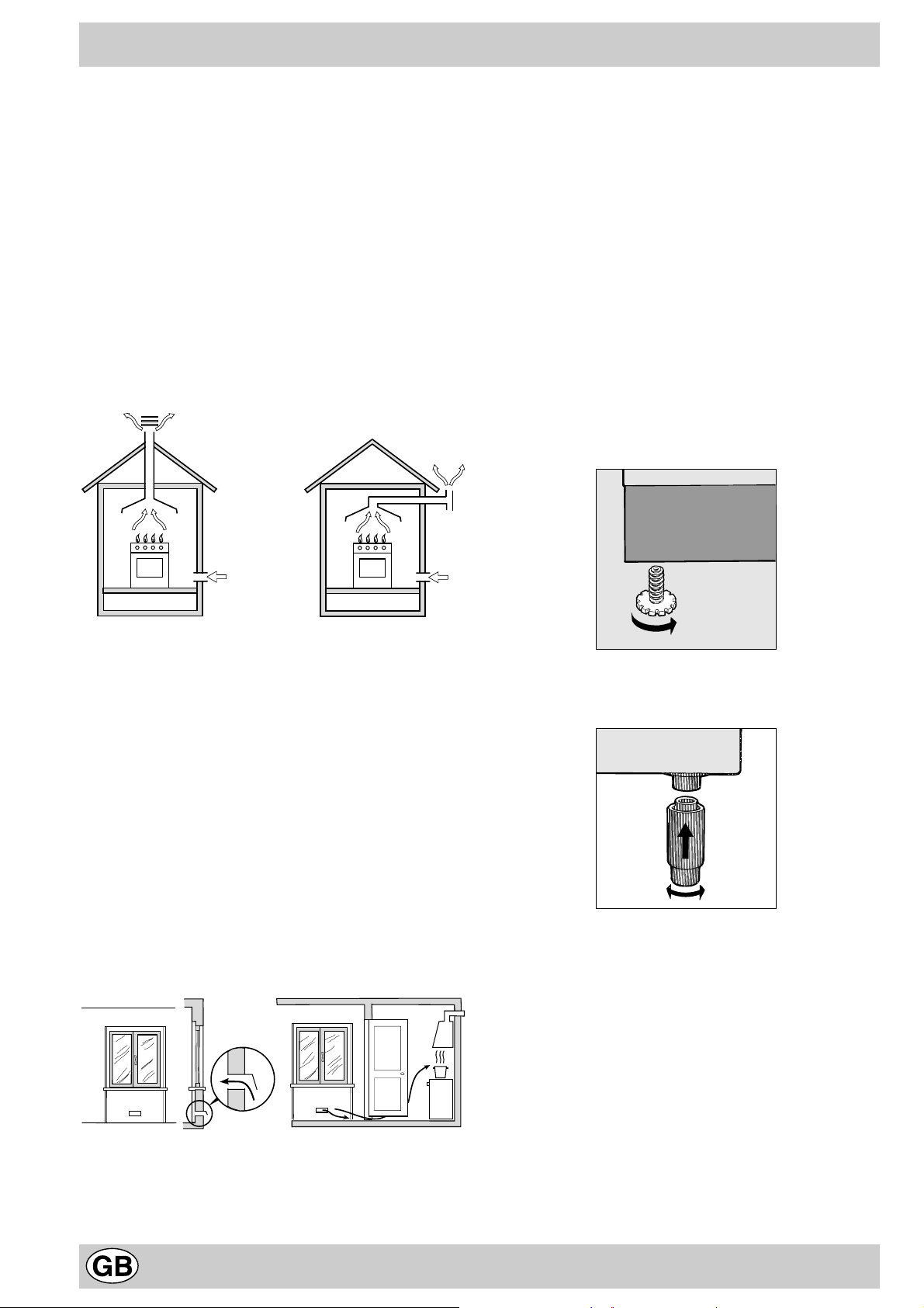
a) The room must be equipped with an exhaust system
that vents the combustion fumes to the outside. It may
consist of a hood or an electric fan that automatically
starts each time the appliance is turned on.
c) Intensive and prolonged use of the appliance may re-
sult in the need for supplemental air circulation, e.g.
opening windows or increasing mechanical venting (if
present).
d) Liquified petroleum gas is heavier than the air and,
therefore, settles downwards. Thus, rooms containing
LPG cylinders must also be equipped with apertures
to the outside for ventilation of gas in the case of leaks.
LPG cylinders must not, therefore, be installed or stored
in rooms or storage areas that are below ground level
(cellars, etc.) whether they are partially or completely
full. It is a good idea to keep only the cylinder being
used in the room, positioned so that it is not subject to
heat produced by external sources (ovens, fireplaces,
stoves, etc. ) which are able to increase the temperature of the cylinder above 50°C.
Levelling Your Appliance (only on certain models)
Your unit is supplied with feet for levelling the appliance. If
necessary, these feet can be screwed into the housings
in the corners of the cooker base.
Flue or Branched Flue System Directly to the Outside
(only for cooking appliances)
b) The room must also have a system to permit proper
air circulation, needed for combustion to occur normally. The flow of air needed for combustion must not
be less than 2 m3/h per kW of installed power. The air
circulation system may take air directly from the outside by means of a pipe with an inner cross section of
at least 100 cm2; the opening must not be able to be
accidentally blocked. For those appliances not
equipped with a safety device for accidental flame loss,
the ventilation apertures must be increased by 100%,
with the minimum being 200cm2 (Fig. A). The system
can also provide the air needed for combustion by indirect means, i.e. from adjacent rooms fitted with air
circulation tubes as described above. However, these
rooms must not be common rooms or bedrooms.
(Fig. B).
Detail A Adjacent Room to
Room be Ventilated
A
Examples of Ventilation Openings Increased Opening Between
Comburent Air Door and Floor
Fig. A Fig. B
Mounting the Legs (only on certain models)
The cooker comes with legs that can be mounted beneath
the base of the cooker itself.
Installing the Cooker
The cooker is manufactured with type X degree protection against overheating. Therefore, the appliance can be
installed next to cabinets, provided they are not taller than
the hob. If the cooker is placed in contact with walls or the
sides of adjacent cabinets, they must be capable of withstanding a rise in temperature of 50°C above room temperature. For proper installation of the cooker, the following precautions must be taken:
a) Kitchen cabinets installed next to the cooker that are
higher than the top of the hob, must be at least 200
mm from the edge of the hob itself.
b) Hoods must be installed according to the requirements
in the installation manual for the hood and, in any case,
at a minimum height of 650 mm.
c) If the hood is installed below a wall cabinet, the latter
14
Page 3
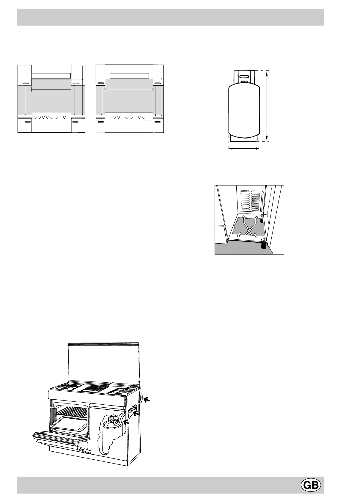
must be at least 700 mm (millimetres) above the surface of the hob. Cabinets installed adjacent to the hood
must be at least 420 mm above the hob, as shown in
Figures C and D.
Cylinder dimensions (only present on some models)
The cylinder’s maximum capacity is to be of 15 Kg and it
must be in line with the dimensions (expressed in
millimetres) as prescribed by the current national
regulations (see figure).
HOOD
Min. mm.
900
420
Min. mm.
min. 650 mm. with hood
mm.
420
Min.
HOOD
Min. mm.
600
mm. with hood
420
650
Min. mm.
min.
mm. without hood
700
min.
mm.
420
Min.
Fig. C Fig. D
Connecting the gas
The appliance should be connected to the mains or to a
gas cylinder in compliance with current directives. Before
making the connection, check that the cooker is regulated
for the gas supply you are using. If not, follow the
instructions indicated in the paragraph “Adapting to
different types of gas”. On some models the gas supply
can be connected on the left or on the right, as necessary;
to change the connection, reverse the position of the hose
holder with that of the cap and replace replace the gasket
(supplied with the appliance). When using liquid gas from
a cylinder, install a pressure regulator which complies with
current directive.
Important: check that the supply pressure complies with
the values indicated in table 1 “Characteristics of the
burners and nozzles” since this will ensure safe operation,
correct consumption and ensure a longer life to your
appliance.
Instructions for the compulsory course of the
flexible hose (only present on some models)
The cooker’s hose holder must be connected to the
cylinder’s pressure regulator by means of a flexible hose
95 cm in length, with its respective hose clamps. This hose
must be inserted in the special support, as illustrated in
the figure, so as to avoid it coming into contact with hot
surfaces. Use flexible hoses and pressure regulators which
conform to current national regulations.
700 mm. without hood
min.
15
Kg
315 mm
650 mm
Cylinder support (supplied only for some models)
A cylinder support consisting of 2 parts, which are fitted
as indicated in figure, are supplied for the models with
legs.
Connection with hose
Make the connection using a gas hose complying with
the the characteristics provided in current directive. The
internal diameter of the pipe used is as follows:
- 8mm for liquid gas;
- 13mm for methane gas.
When installing the hose, remember to take the following
precautions:
• No part of the hose should touch parts whose tempe-
rature exceeds 50°C;
• The length of the hose should be less than 1500 mm;
• The hose should not be subject to twisting or pulling,
and should not have bends or kinks.
• The hose should not touch objects with sharp edges,
any moving parts, and it should not be crushed;
• The full length of the hose should be easy to inspect in
order to check its condition;
Check that the hose fits firmly into place at the two ends
and fix it with clamps complying to current directive.If any
of the above recommendations can not be adopted, flexible
metal pipes should be used.
Should the cooker be installed according to the conditions
of Class 2, subdivision 1, only a flexible metal pipe which
is in compliance with current safety standards should be
used to make the connection to the gas mains.
Connecting a flexible jointless stainless steel pipe
to a threaded attachment
Remove the hose holder fitted on the appliance. The gas
supply pipe fitting is a threaded 1/2 gas cylindrical male
attachment. Only pipes and gaskets complying with current
15
Page 4

directives. The full length of the pipe must not exceed 2000
mm. Once the connection has been made, ensure that
the flexible metal tube does not touch any moving parts
and is not crushed.
Tight control
When installation has been completed, check the pipe
fitting for leaks with a soapy solution. Never use a flame.
Connecting the supply cable to the mains
Install a normalised plug corresponding to the load
indicated on the data plate. When connecting the cable
directly to the mains, install an omnipolar circuit-breaker
with a minimum contact opening of 3 mm between the
appliance and the mains. The omnipolar circuit breaker
should be sized according to the load and should comply
with current regulations (the earth wire should not be
interrupted by the circuit breaker). The supply cable should
be positioned so that it does not reach a temperature of
more than 50°C with respect to the room temperature,
along its length. Before making the connection, check that:
• the limiter valve and the home system can support the
appliance load (see data plate);
• the mains is properly earthed in compliance with
current directives and regulations;
• there is easy access to the socket and omnipolar circuit
breaker, once the hob has been installed.
N.B: never use reducers, adaptors or shunts since they
can cause heating or burning.
Adapting the cooker to different types of gas
In order to adapt the cooker to a different type of gas with
respect to the gas for which it was produced (indicated on
the label attached to the lid), follow these steps:
a) replace the hose holder mounted on the appliance with
that supplied in the bag of “cooker accessories”.
Important: the hose holder for liquid gas is marked 8, the
hose holder for methane gas is marked 13. Always fit the
sealing gasket.
b) Replacing the burner nozzles on the hob:
• remove the grids and slide the burners from their
housings;
• unscrew the nozzles using a 7 mm socket spanner,
(see Fig. E) and replace them with nozzles for the new
type of gas (see table 1 “Burner and nozzle
characteristics”).
• in the case of double-crown burners:
• unscrew the nozzle using the socket spanner
(see fig. F) (available from your local Ariston Branch
Office on request - SAT code 010863), and replace it
with a nozzle for the new gas (see table 1 “Burner and
nozzle characteristics”).
• replace all the components by repeating the steps in
reverse order.
Fig. E Fig. F
c) Minimum regulation of the hob burners:
•
turn the tap to minimum;
• remove the knob and adjust the regulation screw, which
is positioned in or next to the tap pin, until the flame is
small but steady.
N.B.: in the case of liquid gas, the regulation screw
must be screwed in to the bottom.
• check that the flame does not turn off when you turn
the tap quickly from high to low.
d) Regulating the primary air of the burners:
The primary air of the burners requires no regulation.
Important
On completion of the operation, replace the old rating
sticker with one indicating the new type of gas used. This
sticker is available from our Service Centres.
Note
Should the pressure of the gas used be different (or vary)
from the recommended pressure, it is necessary to fit a
suitable pressure regulator onto the inlet pipe in
compliance with current National Regulations relative to
“regulators for channelled gas”.
16
Page 5

Burner and nozzle characteristics
S
R
A
ø 180
Table 1
Burner Diameter
(mm)
Thermal power
kW (p.c.s.*)
Nomin. Ridot. (mm) (mm) *** ** (mm)
Fast
(Large)(R)
Semi Fast
(Medium)(S)
Auxiliary
(Small)(A)
Double Crown
(DC)
Supply
Pressures
90 2,90 0,7 41 85 211 207 132 276
60 1,90 0,4 30 70 138 136 110 181
40 0,86 0,4 30 48 63 61 74 82
120 3,70 1,2 54 94 269 264 142 352
Nominal (mbar)
Minimum (mbar)
Maximum (mbar)
* At 15°C and 1013 mbar-dry gas
** Propane
*** Butane
By-Pass
1/100
Liquid Gas Methane Gas
Nozzle
1/100
28-30
20
35
Flow*
g/h
37
25
45
Nozzle
1/100
20
17
25
Flow*
l/h
ø 180
SS
ø 145
AR
ø 180
SS
DC
A
ø 180
S
R
ø 145
C 980 E...SKD C 975 ED...EX C 522 E...EX C 510 E...CKD
C 975 ED...CKD C 520 E...SKD C 515 E...CKD
Technical characteristics
Dimensions of the oven:
- width cm 40
- depth cm 39
- height cm 34
Volume of oven:
53 liters
Dimensions of food-warmer drawer:
- width cm 43
- depth cm 43
- height cm 13.5
This appliance conforms with the following European
Economic Communitary directives:
- 73/23/EEC of 19/02/73 (Low Voltage) and subsequent;
- 89/336/EEC of 03/05/89 (Electromagnetic
Compatibility) and subsequent;
- 90/396/EEC of 29/06/90 (Gas) and subsequent;
- 93/68/EEC of 22/07/93 and subsequent.
Voltage and frequency of electric supply:
see data plate
Burners:
suitable for any type of gas indicated in the rating plate
17
Page 6

The cooker with electric oven
G
C
E
F
I
H
A
B
A
C
B
E
F
I
H
QO
G
D
K
0
1
6
2
5
3
4
M PL
N
55
5
5
0
0
1
4
5
5
1
4
0
0
2
3
5
25
3
0
QO
0
0
1
6
6
2
5
5
3
4
ML
N
3
4
5
5
5
1
5
0
10
4
5
5
1
2
40
0
2
3
5
5
2
3
0
P
A Tray for catching any overflows
B Electric plate
C Gas burner
D Instant electronic lighting device (only on a few
models)
E Top grate
F Control panel
G Adjustable feet
H Drip pan or cooking plate
K Flame failure device (only on a few models)
I Oven grat shelf
L Electronic ignition (only on a few models)
M The oven knob
N The control knobs for the cook-top gas burners /
electric plate
O The pilot lamp
P The timer knob
Q The thermostat pilot lamp (only on a few models)
18
Page 7

Instructions for use
The various functions featured with the oven are controlled using the knobs and buttons on the control panel.
Control Knobs for the Gas Burners on the Hob (N)
The position of the gas burner controlled by each one of the
knobs is shown by a symbol of a solid ring: • . To light one of the
burners, hold a lighted match or lighter near the burner and, at
the same time, press down and turn the corresponding knob in
the counter-clockwise direction to the maximum setting. Each
burner can be operated at its maximum, minimum or intermedi-
ate power. Shown on the knob are the different symbols for off •
(the knob is on this setting when the symbol lines up with the
reference mark on the control panel), for maximum and
minimum .
To obtain these settings, turn the knob counter-clockwise with
respect to the off position. To turn off the burner, turn the knob
clockwise until it stops (corresponding again with the • symbol).
Electronic Lighting of the Hob Burners (only on a few
models)
Some models are equipped with instant electronic lighting of the
gas burners located on the hob, which can be identified by the
presence of an igniter device (see detail D). This device is acti-
vated by lighting pressing on the “L” button, identified by the
symbol. To turn on a burner, simply press the “L” button and
then press while, at the same time, pressing in and turning the
control knob for the burner in the anticlockwise direction until the
burner lights. To light the burner immediately, it is recom-
mended that the button be pressed first and then the knob
turned.
Caution: If the burner accidentally goes out, turn off the
burner using the knob and wait at least one minute before
relighting.
Models with Hob Gas Burner Safety Devices to Prevent
Leaks (only on a few models)
These models can be identified by the presence of the device
itself (see detail K).
Important: Since the hob burners are equipped with a safety
device, you must hold the control knob in for about 6 seconds
after the burner has been lighted to allow the gas to pass until
the safety thermocouple has heated.
Attention: before using the oven and grill for the first time, turn
the oven on for approximately one half hour. Make sure that the
oven is empty, the thermostat on high, the door open, and the
room properly ventilated. The odor which can be detected at
times is due to the evaporation off the substances used to protect
the oven and the grill during the period between the and
installation of the appliance.
The oven knob (M)
This knob is used to selct the different functions of the oven and
choose the right cooking temperature for the food to be prepared
in the oven from among the temperatures shown on the knob
(from 60°C to 240°C). By turning the knob clockwise to the
position indicated by the symbol , the oven lamp lights up
without turning on the heating elements. By continuing to turn
the knob clockwise both the upper and the lower heating element
(electric resistances) begin working. It is possible to choose,
from among the complete range of temperatures here below,
the right cooking temperature for the food to be prepared. To do
so, match the desired temperature value shown with the
permanent reference on the panel.
60 • 100 • 140 • 180 • 220 Max
80 120 160 200 240
This temperature is reached automatically and kept constant by
the knob-controlled thermostat. The oven lamp indicates that
the oven is in use and stays on during cooking.
Position bottom heating element
It is possible to use only the lower heating element by turning the
knob past the MAX. Setting and onto the setting marked .
On this setting the oven will heat up slowly until it reaches
maximum (240°C) at which temperature it will be maintained. It
is not possible to use this function on lower setting. This setting is
recommended for finishing the cooking of foods in containers
that are well done on the outside but still not done inside, or for
desserts covered with fruit or jam which requires a light browning
on top.
Double grill position
Turning the oven knob till to this position, the oven light turns on,
so does the double heating element of the grill, and the motor
starts turning the spit. This grill is larger than the average and
has a completelly new design: cooking performance is increased
50%. The double grill makes sure that even the corners are
touched by heat.
The rotisserie
Starting the rotisserie. When using the rotisserie act in this way:
a) fit supporting hook into the two holes in the lower side of the
grill protection (position 1);
b) fit the spit into the hole in the centre of the back of the oven,
making sure that the fore clasping link of the spit is correctly
positioned on the supporting hook (position 2);
c) start the turn-spit by setting the oven knob at position .
Attention: Only use the bottom shelf of the oven when
using the rotisserie to cook (where present). For all other
types of cooking, never use the bottom shelf and never
place anything on the bottom of the oven when it is in
operation because this could damage the enamel. Always
place your cookware (dishes, aluminium foil, etc. etc.) on
the grate provided with the appliance inserted especially
along the oven guides.
1
1
2
19
Page 8

The cook-top electric plate control knobs (N)
The cookers may be equipped with standard and fast electric
plates in various combinations (the fast plates distinguished from
the others by a red dot in the centre). To avoid heat dispersion
and damage to the plates, recommend using cooking vessels
with flat bottoms in diameters which are not smaller than the
plate diameter. Table shows the correspondence between the
position indicated on the knobs and the use for which the plates
advised.
Setting Normal or Fast Plate
0
1
2
3
4
5
6
The pilot lamp (O)
This turns on whenever any electric heating element in the cooktop.
Off
Cooking vegetables, fish
Cooking potatoes (using steam) soups,
chickpeas, beans.
Continuing the cooking of large quantities of
food, minestrone
For roasting (average)
For roasting (above average)
For browning and reaching a boil in a short
time.
The timer knob (P)
To use the timer the ringer must be wound up by turning the
knob one full turn clockwise; then turn it back to the desired time
so that the number of minutes on the knob matches the reference
mark on the panel.
The oven pilot lamp (Q) (only on a few models)
This lamp is on during the heating phase and turns off when the
temperature set by the knob has been reached in the oven. At
this point the alternate turning on and off of the lamp shows that
the thermostat is working correctly to keep the oven temperature constant.
Attention
Avoid the children touch the oven door because it is very hot
during the cooking.
3rd Oven Glass
In order to further decrease the temperature of the oven door
during operation, as well as reducing energy consumption, an
additional protective kit has been made available. This kit should
be installed if the oven is used in the presence of small children.
To do this, you should purchase the spare part kit no.:
• 039104 with double internal screw-in glass
• 066160 with internal glued-on glass
from an authorised retailer or from your nearest Technical Service
Centre as indicated on the list provided with the appliance.
Cooking advice
The oven offers a wide range of alternatives which allow you to
cook any type of food in the best possible way. The various
functions allow you to direct heat as required: from below, from
above or evenly and with the required intensity. With time you will
learn to make the best use of this versatile cooking appliance
and the following directions are only a guideline which may be
varied according to your own personal experience.
Baking cakes
The oven should always be warm before putting in cakes wait till
the ednd of preheating (about 15 min.) or till the thermostat lamp
(P) turns off. Cake-baking temperatures are normally around
160°C. Do not open the oven door during the baking process as
this could cause the cake to sink. Beaten cake mixtures should
not be too soft as this could considerably lengthen cooking times.
In general:
Pastry is too dry
Increase the temperature by 10°C and reduce the
cooking time.
Pastry dropped
Use less liquid or lower the temperature by 10°C.
Pastry is too dark on top
Place it on a lower rack, lower the temperature, and
increase the cooking time.
Cooked well on the inside but sticky on the outside
Use less liquid, lower the temperature, and increase the
cooking time.
The pastry sticks to the pan
Grease the pan well and sprinkle it with a dusting of
flour.
I used more than one level and they are not all at
the same cooking point
Use a lower temperature setting. It is not necessary to
remove the food from all the racks at the same time.
Cooking fish and meat
Meat must weigh at least one Kg. to stop it becoming too dry.
When cooking white meat, fowl and fish use low temperatures.
(150°C-175°C). When red meat must be superficially well-cooked
but succulent inside, it is advisable to start with a high temperature (200°C-220°C) for a short time, and then to reduce it at a
later point. Generally speaking, the more meat there is, the lower
the temperature and the longer the cooking time should be. Place
the meat in the centre of the grid and put a spill-tray underneath
to catch grease drips. Insert the grid so that it is in the middle of
the oven. If more heat from below is required, use the 1° bottom
shelf. For tastier roasts, wrap the meat with bacon rashers or dot
20
Page 9

the meat with lard and place it in the upper part of the oven.
Using the grill
The “double grill” position heats the entire surface of grill.
Use the position for evenly spread food requiring uniform
browning.
Pratical advice for oven cooking
Important: when using the grill, keep the oven door closed,
to obtain the best result and save energy (about 10%).
The table show the temperatures, cooking times and positions
recommended for obtaining the best cooking results.
When utilizing the grill, place the rack at the lower levels (see
cooking table). To catch grease or fat and prevent smoke, place
a dripping-pan at the bottom rack level.
Food to be cooked
Pasta
Lasagne 2.5 3 210 - 75-80
Cannelloni 2.5 3 210 - 75-80
Pasta bakes 2.5 3 210 - 75-80
Meat
Veal 1.7 3 230 - 85-90
Chicken 1.5 3 220 - 110-115
Turkey 3.0 3 MAX - 95-100
Duck 1.8 3 230 - 120/125
Rabbit 2 3 230 - 105/110
Pork 2.1 3 230 - 100/110
Lamb 1.8 3 230 - 90-95
Fish
Mackerel 1.1 3 210-230 - 55-60
Dentex 1.5 3 210-230 - 60-65
Wt.
(Kg)
Cooking position of
shelves from
bottom
Temperature
(°C)
Pre-heating time
(min)
Cooking time
(min.)
Trout baked in paper 1.0 3 210-230 - 40-45
Pizza
Neapolitan 1.0 3 MAX 15 30-35
Cake
Biscuits 0.5 3 180 15 30-35
Tarts 1.1 3 180 15 30-35
Chocolate cake 1 3 200 15 45-50
Raised Cakes 1 3 200 15 50/55
Grill cooking
Toasted sandwiches n.° 44 10
Pork chops 1.5 4 30
Mackerel 1.1 4 35
Rotisserie
Veal on the spit 1 2 80
Chicken on the spit 2 2 90
NB:
cooking times are approximate and may vary according to personal taste.
21
Page 10

Cooker routine maintenance and cleaning
Before each operation, disconnect the cooker from
the electricity.To assure the long life of the cooker, it must
be thoroughly cleaned frequently, keeping in mind that:
· the enamelled parts and the self-cleaning panels are
washed with warm water without using any abrasive
powders or corrosive substances which could ruin
them;
· the inside of the oven should be cleaned fairly often
while it is still warm using warm water and detergent,
followed by careful rinsing and drying;
· the flame spreaders should be washed frequently with
hot water and detergent taking care to eliminate any
scale;
· in cookers equipped with automatic lighting, the
terminal part of the electronic instant lighting devices
should be cleaned frequently and the gas outlet holes
of the flame spreaders should be checked to make
sure they are free of any obstructions;
· the electric plates are cleaned with a damp cloth and
they should be lubricated with a little oil while they still
warm;
· stainless steel may become marked if it comes into
contact with very hard water or harsh detergents
(containing phosphorous) for long periods of time. After
cleaning, it is advisable to rinse thoroughly and dry. It
is also recommended to dry any water drops;
· in models with glass covers, the covers are cleaned
with hot water and use of rough cloths or abrasives is
to be avoided.
N.B: avoid closing the cover while the gas burners
and electric plates are still warm.
Important: periodically check the wear of the gas hose
and substitute it if there are any defects; we recommended
changing it every year.
Replacing the oven lamp
· Unplug the oven from the mains;
· Remove the glass cover of the lamp-holder;
· Remove the lamp and replace with a lamp resistant to
high temperatures (300°C) with the following
characteristics:
- Voltage 230V
- Wattage 25W
- Type E14
· Replace the glass over and connect the oven to the
mains.
Greasing the taps
The taps may jam in time or they may become difficult to
turn. If so, they must be cleaned internally and the grease
replaced.
N.B: This operation must be carried by a technician
authorised by the manufacturer.
22
 Loading...