

Page 1

Avvertenze
Per garantire l’efficienza e la sicurezza di questo elettrodomestico:
• rivolgetevi esclusivamente a centri di assistenza tecnica autorizzati
• richiedete sempre l’utilizzo di parti di ricambio originali
1 Queste istruzioni sono valide solo per i paesi di destina-
zione i cui simboli figurano sul libretto e sulla targa matricola dell’apparecchio.
2 Questo apparecchio è stato concepito per un uso di tipo
non professionale all'interno di abitazione.
3 Questo libretto riguarda un apparecchio di classe 1 (isola-
to) o classe 2 - sottoclasse 1 (incassato tra 2 mobili).
4 Prima di utilizzare l'apparecchio, leg gere attentamente le
avvertenze contenute nel presente libretto in quanto forniscono importanti indicazioni riguardanti la sicurezza di
installazione, d’uso e di manutenzione. Conservare con
cura questo libretto per ogni ulteriore consultazione.
5 Dopo aver tolto l’imballaggio assicurarsi dell’integrità dell’ap-
parecchio. In caso di dubbio non utilizzare l’apparecchio e rivolgersi a personale professionalmente qualificato . Gli elementi
dell’imballaggio (sacchetti in plastica, polistirolo espanso, chiodi, ecc.) non devono essere lasciati alla portata dei bambini in
quanto potenziali fonti di pericolo.
6 L’installazione deve essere eff ettuata secondo le istruzioni del
costruttore da personale professionalmente qualificato. Una
errata installazione può causare danni a persone, animali o
cose, nei confronti dei quali il costruttore non può essere considerato responsabile.
7 La sicurezza elettrica di questo apparecchio è assicurata sol-
tanto quando lo stesso è correttamente collegato ad un efficiente impianto di messa a terra come previsto dalle vigenti
norme di sicurezza elettrica. E’ necessario verificare questo
fondamentale requisito di sicurezza e, in caso di dubbio , richiedere un controllo accurato dell’impianto da parte di personale
professionalmente qualificato . Il costruttore non può essere considerato responsabile per eventuali danni causati dalla mancanza di messa a terra dell’impianto.
8 Prima di collegare l’apparecchio accertarsi che i dati di targa
siano rispondenti a quelli della rete di distribuzione elettrica e
gas.
9 V erificare che la portata elettrica dell’impianto e delle prese di
corrente siano adeguate alla potenza massima dell’apparecchio indicata in targa. In caso di dub bio rivolgersi ad una persona professionalmente qualificata.
10 All’installazione occorre prevedere un interruttore omnipolare
con distanza di apertura dei contatti uguale o superiore a 3
mm.
11 In caso di incompatibilità tra la presa e la spina dell’apparec-
chio fare sostituire la presa con altra di tipo adatto da personale professionalmente qualificato. Quest’ultimo, in par ticolare,
dovrà anche accertare che la sezione dei cavi della presa sia
idonea alla potenza assorbita dall’apparecchio. In generale è
sconsigliabile l’uso di adattatori, prese multiple e/o prolunghe.
Qualora il loro uso si rendesse indispensabile è necessario
utilizzare solamente adattatori semplici o multipli e prolunghe
conformi alle vigenti norme di sicurezza, facendo però attenzione a non superare il limite di portata in valore di corrente,
marcato sull’adattatore semplice e sulle prolunghe, e quello di
massima potenza marcato sull’adattatore multiplo.
12 Non lasciare l’apparecchio inutilmente inserito. Spegnere l’in-
terruttore generale dell’apparecchio quando lo stesso non è
utilizzato, e chiudere il rubinetto del gas.
13 Non ostruire le aperture o fessure di ventilazione o di
smaltimento calore.
14 Il cavo di alimentazione di questo apparecchio non dev e esse-
re sostituito dall’utente. In caso di danneggiamento del cavo , o
per la sua sostituzione, rivolgersi esclusivamente ad un centro
di assistenza tecnica autorizzato dal costruttore.
15 Questo apparecchio dovrà essere destinato solo all’uso per il
quale è stato espressamente concepito. Ogni altro uso (ad
esempio: riscaldamento di ambienti) è da considerarsi improprio e quindi pericoloso. Il costruttore non può essere considerato responsabile per eventuali danni deriv anti da usi impropri,
erronei ed irragionevoli.
16 L’uso di un qualsiasi apparecchio elettrico compor ta l’osser-
vanza di alcune regole fondamentali. In particolare:
· non toccare l’apparecchio con mani o piedi bagnati o umidi
· non usare l’apparecchio a piedi nudi
· non usare, se non con particolare cautela, prolunghe
· non tirare il cavo di alimentazione , o l’apparecchio stesso,
per staccare la spina dalla presa di corrente.
· non lasciare esposto l’apparecchio ad agenti atmosferici
(pioggia, sole, ecc.)
· non permettere che l’apparecchio sia usato dai bambini o
da incapaci, senza sorveglianza
17 Prima di effettuare qualsiasi operazione di pulizia o di manu-
tenzione, disinserire l’apparecchio dalla rete di alimentazione
elettrica, o staccando la spina, o spegnendo l’interruttore dell’impianto.
18 Allorchè si decida di non utilizzare più di un apparecchio di
questo tipo, si raccomanda di renderlo inoperante tagliandone
il cavo di alimentazione, dopo a ver staccato la spina dalla presa di corrente. Si r accomanda inoltre di rendere innocue quelle
parti dell’apparecchio suscettibili di costituire un pericolo, specialmente per i bambini che potrebbero servirsi dell’apparecchio fuori uso per i propri giochi.
19 Sui bruciatori e sulle piastre elettriche non debbono essere
poste pentole instabili o deformate onde evitare incidenti per
rovesciamento.
20 Non lasciate le piastre di cottura accese senza pentole, in quanto
si avrebbe un riscaldamento massimo in poco tempo, con possibili danni dell’apparecchio o dei mobili circostanti.
21 Alcune parti dell’apparecchio, in particolare le piastre elettri-
che, rimangono calde per lungo tempo dopo l’uso. F ate attenzione a non toccarle.
22 Non utilizzate liquidi infiammabili (alcool, benzina...) in vicinan-
za all’apparecchio mentre questo è in uso.
23 Usando piccoli elettrodomestici nelle vicinanze del piano fate
attenzione che il cavo di alimentazione non finisca su parti calde
24 Controllare sempre che le manopole siano nella posizione “·”/
¡
“
” quando l’apparecchio non è utilizzato .
Durante l'uso dell'apparecchio gli elementi riscaldanti
25
e alcune parti della porta forno diventano molto calde.
Fare attenzione a non toccarle e tenere i bambimi a distanza.
26 Gli apparecchi gas necessitano, per un corretto funziona-
mento, di un regolare ricambio d’aria. Accertarsi che nella
loro installazione siano rispettati i requisiti richiesti nel
paragrafo relativo al “Posizionamento”.
27 Se la cucina viene posta su di un piedistallo, prendere ade-
guati accorgimenti affinchè l'apparecchio non scivoli dal piedistallo stesso.
2
Page 2
Istruzioni per l’installazione
Le istruzioni che seguono sono rivolte all’installatore qualificato affinchè compia le operazioni di installazione
regolazione e manutenzione tecnica nel modo più corretto e secondo le norme in vigore.
Importante: qualsiasi intervento di regolazione, manutenzione etc. deve essere eseguito con la cucina
elettricamente disinserita.
Posizionamento
Importante: questo apparecchio può essere installato e
funzionare solo in locali permanentemente ventilati secondo le prescrizioni delle Norme UNI-CIG 7129 e 7131
in vigore. Deb bono essere osservati i seguenti requisiti:
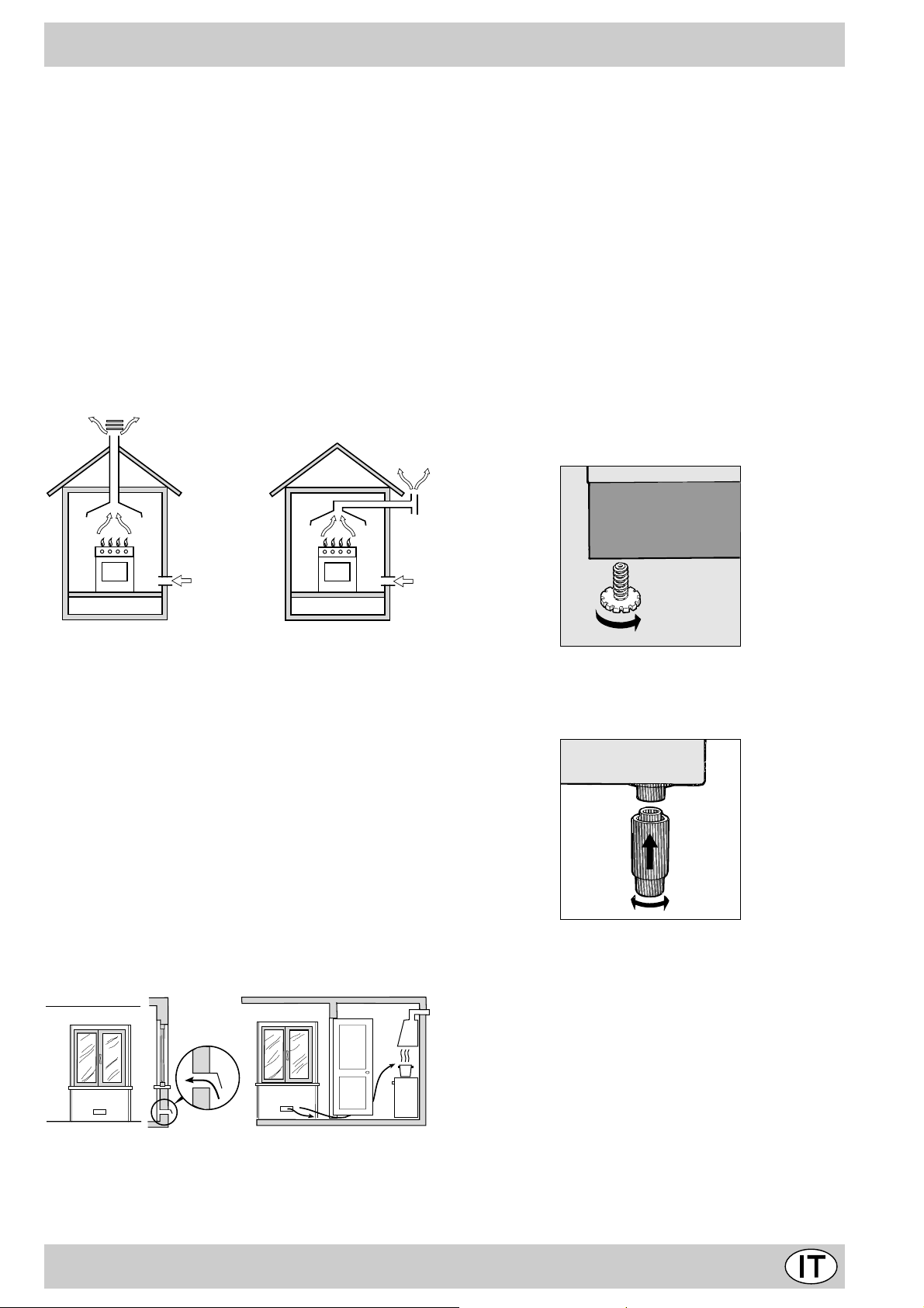
a) Il locale deve pre vedere un sistema di scarico all’ester-
no dei fumi della combustione, realizzato tramite una
cappa o tramite un elettroventilatore che entri automaticamente in funzione ogni volta che si accende l’apparecchio.
cace aumentando la potenza di spirazione meccanica
se essa esiste.
d) I gas di petrolio liquefatti, più pesanti dell’aria, rista-
gnano verso il basso. Quindi i locali contenenti bidoni
di GPL debbono prevedere delle aperture verso l’esterno così da permettere l’evacuazione dal basso delle
eventuali fughe di gas . Pertanto i bidoni di GPL, siano
essi vuoti o parzialmente pieni, non debbono essere
installati o depositati in locali o vani a livello più basso
del suolo (cantinati, ecc.). É opportuno tenere nel locale solo il bidone in utilizzo, collocato in modo da non
essere soggetto all’azione diretta di sorgenti di calore
(forni, camini, stufe, ecc.) capaci di portarlo a temperature superiori ai 50°C.
Livellamento
Per poter livellare la cucina vengono forniti dei piedini di
regolazione. In caso di necessità questi piedini possono
essere avvitati nelle apposite sedi poste negli angoli alla
base della cucina.
In camino o in canna fumaria ramificata Direttamente all’esterno
(riservata agli apparecchi di cottura)
b)
Il locale deve prevedere un sistema che consenta l’afflusso dell’aria necessaria alla regolare combustione.
La portata di aria necessaria alla combustione non dev e
essere inferiore a 2 m3/h per kW di potenza installata. Il
sistema può essere realizzato prelevando direttamente
l’aria dall’esterno dell’edificio tramite un condotto di almeno 100 cm2 di sezione utile e tale che non possa
essere accidentalmente ostruito. Per gli apparecchi privi sul piano di lavoro, del dispositivo di sicurezza per
assenza di fiamma, le aperture di ventilazione debbono
essere maggiorate nella misura del 100%, con un minimo di 200cm2 (Fig. A). Ovvero, in maniera indiretta da
locali adiacenti, dotati di un condotto di ventilazione con
l’esterno come sopra descritto, e che non siano parti
comuni dell’immobile, o ambienti con pericolo di incendio, o camere da letto (Fig. B).
Particolare A Locale Locale da
A
Esempi di aperture di ventilazione Maggior azione della f essura fra
per l’aria comburente porta e pavimento
adiacente ventilare
Fig. A Fig. B
c) Un utilizzo intensivo e prolungato dell’apparecchio può
necessitare di una aerazione supplementare per esempio l’apertura di una finestra o una aerazione più effi-
Montaggio gambe (presente solo su alcuni modelli)
V engono fornite delle gambe da montare ad incastro sotto la base della cucina.
Installazione della cucina
E' possibile l’installazione a fianco di mobili la cui altezza non
superi quella del piano di lavoro. La parete a contatto con la
parete posteriore della cucina deve essere in materiale
ininfiammabile. Durante il funzionamento la parete posteriore
della cucina può raggiungere una temperatura di 50°C superiore a quella ambiente.
Per una corretta installazione della cucina vanno osservate le seguenti precauzioni:
a) I mobili situati a fianco, la cui altezza superi quella del
piano di lavoro , debbono essere situati ad almeno 110
mm. dal bordo del piano stesso.
b) Le cappe debbono essere installate secondo i requisi-
ti richiesti nei libretti istruzioni delle cappe stesse e comunque ad una distanza minima di 650 mm.
c) Allorchè la cucina venga installata sotto un pensile,
3
Page 3
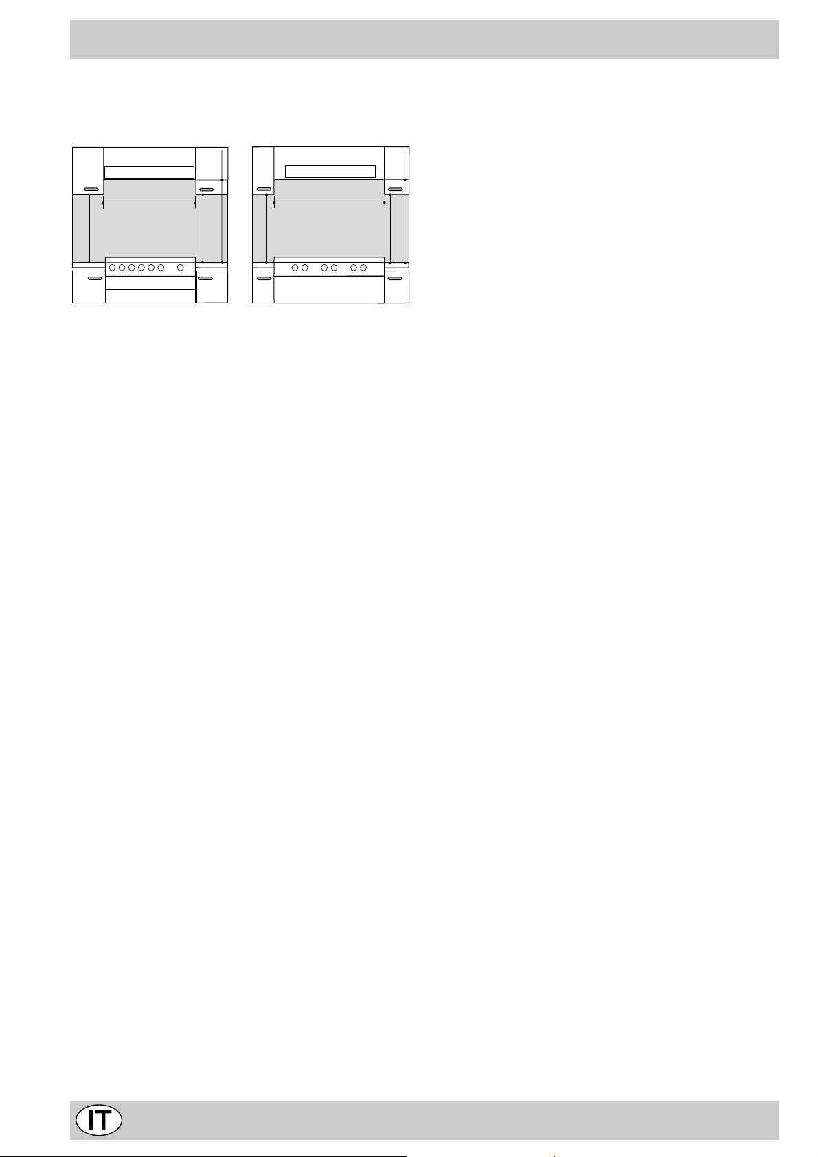
quest’ultimo dovrà mantenere una distanza minima dal
piano di 700 mm (millimetri). I mobili adiacenti alla cappa
dovranno mantenere una distanza minima dal piano di
420 mm. come da Fig. C e D.
forme alla UNI-CIG 9891.
Allaccio con tubo flessibile in acciaio inossidabile a
parete continua con attacchi filettati
Eliminare il portagomma già presente sull’apparecchio. Il
raccordo di entrata del gas all’apparecchio è filettato 1/2
HOOD
Min. mm.
900
mm. with hood
420
650
Min. mm.
min.
gas maschio cilindrico. Utilizzare esclusivamente tubi conformi alla Norma UNI-CIG 9891 e guar nizioni di tenuta
conformi alla UNI-CIG 9264. La messa in opera di tali tubi
deve essere effettuata in modo che la loro lunghezza, in
mm. without hood
condizioni di massima estensione, non sia maggiore di
700
min.
2000 mm.
mm.
420
Min.
HOOD
Min. mm.
600
mm. with hood
420
650
Min. mm.
min.
mm. without hood
700
min.
mm.
420
Min.
Controllo tenuta
Importante: ad installazione ultimata controllare la perfetta te-
Fig. C Fig. D
Collegamento gas
Il collegamento dell’apparecchio alla tubazione o alla bombola
del gas dovrà essere effettuato come prescritto dalle Norme UNICIG 7129 e 7131, solo dopo essersi accertati che esso è regolato per il tipo di gas con cui sarà alimentato. In caso contrario
eseguire le operazioni indicate al paragraf o “Adattamento ai diversi tipi di gas”. Su alcuni modelli l’alimentazione del gas può
avvenire indiff erentemente da destra o da sinistra a seconda dei
casi; per cambiare il collegamento è necessario invertire il
portagomma con il tappo di chiusura e sostituire la guarnizione
di tenuta (in dotazione con l’apparecchio). Nel caso di alimentazione con gas liquido, da bombola, utilizzare regolatori di pressione conformi alle Norme UNI-CIG 7432.
Importante: per un sicuro funzionamento, per un adeguato uso
dell’energia e maggiore durata dell’apparecchiatura, assicurarsi che la pressione di alimentazione rispetti i valori indicati nella
nuta di tutti i raccordi utilizzando una soluzione saponosa e mai
una fiamma.
Ad allacciamento avvenuto assicur arsi che il tubo metallico flessibile non venga a contatto con parti mobili o schiacciato.
Allacciamento del cavo di alimentazione alla rete
Montare sul cavo una spina normalizzata per il carico indicato sulla targhetta caratteristiche, nel caso di collegamento diretto alla rete è necessario interporre tra l’apparecchio e la rete un interruttore omnipolare con apertura
minima fra i contatti di 3 mm. dimensionato al carico e
rispondente alle norme in vigore (il filo di terra non deve
essere interrotto dall’interruttore). Il cavo di alimentazione deve essere posizionato in modo che non raggiunga
in nessun punto una temperatura superiore di 50°C a
quella ambiente. Prima di effettuare l’allacciamento accertarsi che:
• la valvola limitatrice e l’impianto domestico possano
tabella 1 “Caratteristiche dei bruciatori ed ugelli”.
Allaccio con tubo flessibile
Eseguire il collegamento per mezzo di un tubo flessibile
• l’impianto di alimentazone sia munito di efficace colle-
per gas rispondente alle caratteristiche indicate nelle norme UNI-CIG 7140. Il diametro interno del tubo da utilizzare deve essere:
• la presa o l’interruttore omnipolare siano facilmente
- 8mm per alimentazione con gas liquido;
- 13mm per alimentazione con gas metano o gas città.
In particolare, per la messa in opera di tali tubi flessibili,
debbono essere rispettate le seguenti prescrizioni:
• Non deve essere in nessun punto del suo percorso a
contatto con parti che siano a temperature maggiori di
50°C;
• Abbia una lunghezza inferiore a 1500 mm;
• Non sia soggetto ad alcun sforzo di trazione e di tor-
N.B: non utilizzare riduzioni, adattatori o derivatori in quanto essi potrebbero provocare riscaldamenti o bruciature.
Adattamento del piano ai diversi tipi di gas
Per adattare la cucina ad un tipo di gas div erso da quello
per il quale essa è predisposta (indicato sulla etichetta
fissata al coperchio), occorre effettuare le seguenti operazioni:
a) Sostituire il portagomma già montato con quello con-
sione, inoltre non deve presentare curve eccessivamente strette o strozzature;
• Non venga a contatto con corpi taglienti, spigoli vivi e
con parti mobili o schiacciato;
• Deve essere facilmente ispezionabile lungo tutto il per-
corso allo scopo di poter controllare il suo stato di con-
servazione;
Assicurarsi che il tubo sia ben calzato alle sue due estremità e fissarlo per mezzo di fascette di serraggio conformi
Attenzione: il portagomma per gas metano e per gas città è lo stesso. (Il portagomma per gas liquido porta
stampigliato il numero 8, quello per gas metano e gas
città il numero 13). A vv alersi comunque di una guarnizione di tenuta nuova.
b) Sostituzione degli ugelli dei bruciatori del piano:
• togliere le griglie e sfilare i bruciatori dalle loro sedi;
• svitare gli ugelli, servendosi di una chiave a tubo da 7
alla UNI-CIG 7141. Qualora una o più di queste condizioni
non possa essere rispettata, bisognerà ricorrere ai tubi
metallici flessibili, conformi alla norma UNI-CIG 9891.
• rimettere in posizione tutti i componenti seguendo le
Allorchè la cucina venga installata secondo le condizioni
della classe 2 sottoclasse 1 è opportuno collegarsi alla
rete gas solamente tramite tubo metallico flessibile con-
sopportare il carico dell’apparecchiatura (vedi targhetta
caratteristiche);
gamento a terra secondo le norme e le disposizioni di
legge;
raggiungibili con il piano installato.
tenuto nella confezione “accessori della cucina”.
mm, e sostituirli con quelli adatti al nuovo tipo di gas
(vedi tabella 1 “Caratteristiche dei bruciatori ed ugelli”).
operazioni inverse rispetto alla sequenza di cui sopra.
4
Page 4
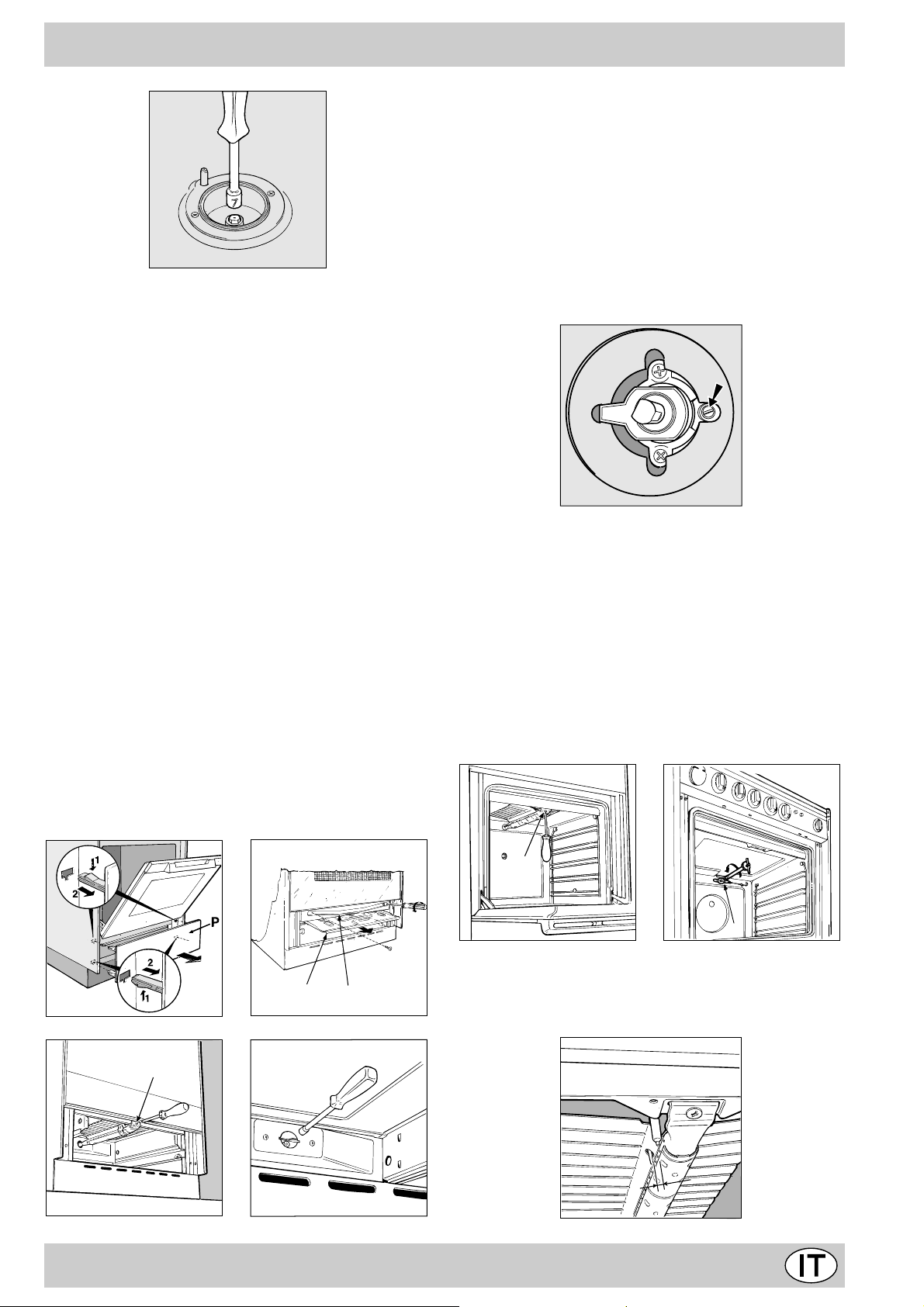
c) Regolazione minimi dei bruciatori del piano:
4
m
m
•
portare il rubinetto sulla posizione di minimo;
• togliere la manopola ed agire sulla vite di regolazione
posta all’interno o di fianco all’astina del rubinetto fino
ad ottenere una piccola fiamma regolare.
N.B.: nel caso dei gas liquidi, la vite di regolazione
dovrà essere avvitata a fondo.
• verificare poi che ruotando rapidamente il rubinetto
dalla posizione di massimo a quella di minimo, non si
abbiano spegnimenti del bruciatore.
d) Regolazione aria primaria dei bruciatori del piano:
I bruciatori non necessitano di alcuna regolazione dell’aria primaria.
Adattamento del forno gas ai diversi tipi di gas
a) Sostituzione dell’ugello del bruciatore del forno:
• togliere il cassetto scaldavivande;
• nei modelli senza cassetto togliere il pannello “P” come
indicato in Fig. E. Dopo a ver aperto la porta, sganciare
i due inserti superior i premendoli verso il basso, poi i
due inferiori premendoli verso l’alto;
• sfilare la protezione scorrevole “A”;
• togliere le due viti che consentono lo smontaggio della
protezione “B”; (v edi Fig. F);
• rimuovere il bruciatore del forno dopo aver tolto la vite
“V” (v edi Fig. G); L’ operazione viene facilitata togliendo la porta del forno.
• svitare l’ugello del bruciatore forno servendosi dell’apposita chiave a tubo per ugelli (vedi Fig. H), o meglio
ancora di una chiave a tubo di 7 mm e sostituirlo con
quello adatto al nuovo tipo di gas (v edi tabella 1).
b) Regolazione del minimo del bruciatore forno gas
termostatato (vedi figura):
• accendere il bruciatore come descritto al paragraf o “la
manopola del forno” del libretto d’uso;
• portare la manopola sulla posizione di Min dopo aver
lasciato la stessa per 10 minuti circa in posizione Max;
• togliere la manopola;
• agire sulla vite di regolazione posta all’esterno
dell’astina del termostato fino ad ottenere una
piccola fiamma regolare;
N.B.: nel caso dei gas liquidi, la vite di regolazione
dovrà essere avvitata a f ondo.
• verificare poi che ruotando rapidamente la manopola
dalla posizione Max alla posizione di Min o con rapide
aperture e chiusure della porta del forno non si abbiano spegnimenti del bruciatore.
Adattamento del grill gas ai diversi tipi di gas
Sostituzione dell’ugello del bruciatore del grill:
• rimuovere il bruciatore del grill dopo aver tolto la vite
“V” (v edi Fig. I);
• svitare l’ugello del bruciatore gr ill ser vendosi dell’apposita chiave a tubo per ugelli (vedi Fig. L), o meglio
ancora di una chiave a tubo di 7 mm e sostituirlo con
quello adatto al nuovo tipo di gas (v edi tabella 1).
A
Fig. E Fig. F
V
Fig. G Fig. H
V
I
Fig. I Fig. L
B
Attenzione: rimontando il bruciatore del grill verificare che
la distanza tra la termocoppia di sicurezza (se presente)
e il bruciatore sia di 4 mm.
5
Page 5
Regolazione aria primaria dei bruciatori forno e grill
I bruciatori forno e grill non necessitano di alcuna
regolazione dell’aria primaria.
Attenzione
Al termine dell’operazione sostituire la vecchia etichetta
Qualora la pressione del gas utilizzato sia diversa (o variabile) da quella prevista, è necessario installare, sulla
tubazione d’ingresso un appropriato regolatore di pressione (secondo UNI-CIG 7430 “regolatori per gas
canalizzati”).
di taratura con quella corrispondente al nuovo gas di utilizzo, reperibile presso i nostri Centri Assistenza Tecnica.
Nota
Caratteristiche dei bruciatori ed ugelli
Tabella 1 Gas Liquido Gas Naturale
Bruciatore Diametro
(mm)
Potenza termica
kW (p.c.s.*)
By-Pass
1/100
ugello
1/100
portata*
g/h
ugello
1/100
portata*
Nomin. Ridot. ( mm) (mm) *** ** (mm)
Rapido
(Grande)(R)
Semi Rapido
(Medio)(S)
Ausiliario
(Piccolo)(A)
100 3.00 0.7 41 86 218 214 116 286
75 1.90 0.4 30 70 138 136 106 181
55 1.00 0.4 30 50 73 71 79 95
Forno - 3.02 1.0 49 85 219 216 132 288
Grill - 2.50 - - 80 182 179 122 227
Pressioni di
alimentazione
Nominale (mbar)
Minima (mbar)
Massima (mbar)
28-30 ***
20 ***
35 ***
37 **
25 **
45 **
20
17
25
* At 15°C and 1013 mbar- dry gas
** Propano P.C.S . = 50,37 MJ/Kg
*** Butano P.C.S. = 49,47 MJ/Kg
Naturale P.C.S . = 37,78 MJ/m
3
l/h
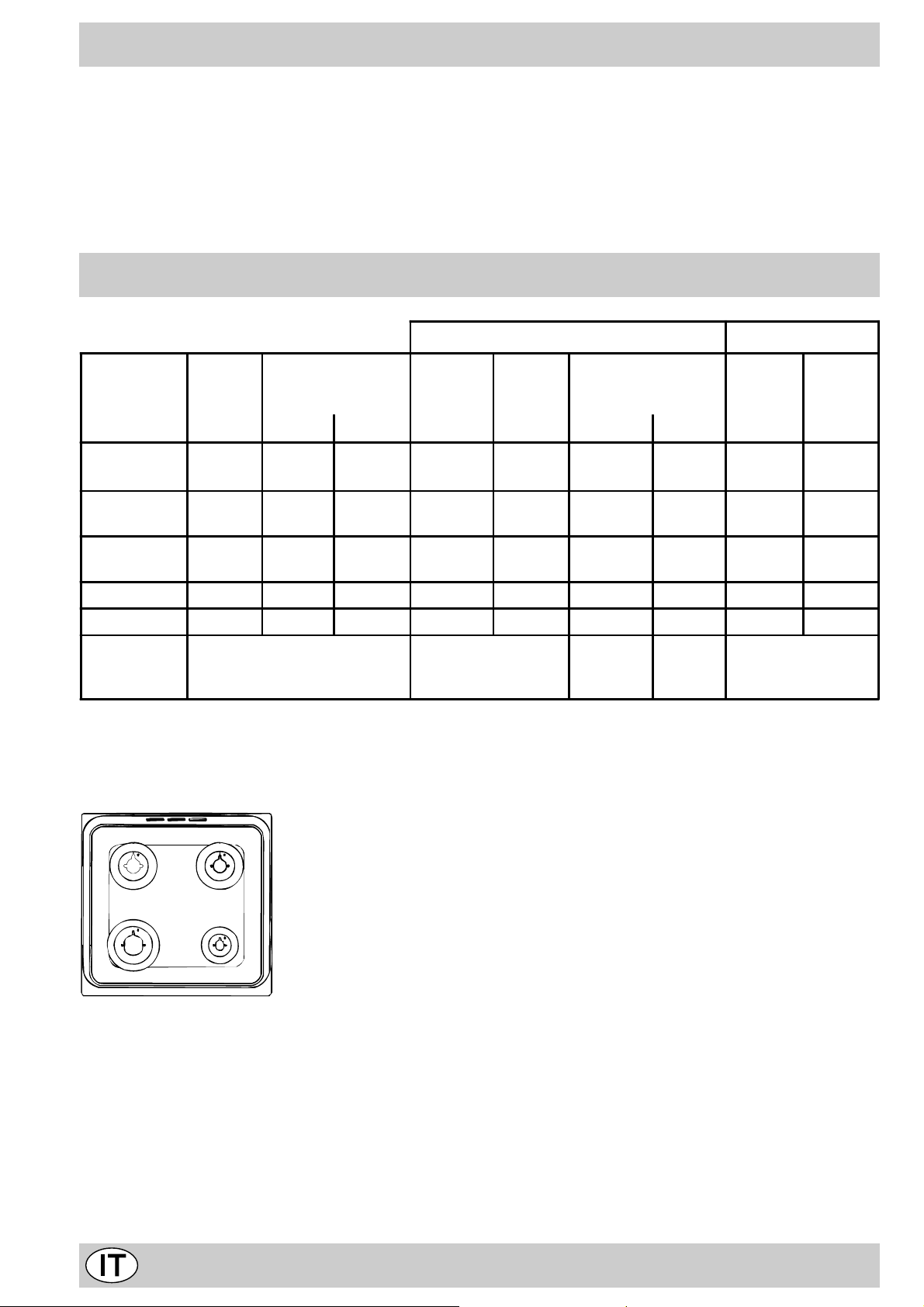
C 647 G...R
S
S
R
A
6
Page 6
Caratteristiche T ecniche
Dimensioni utili del forno:
larghezza cm 40,5
profondità cm 39,5
altezza cm 32
Volume utile del forno:
Dimensioni utili del cassetto scaldavivande:
larghezza cm 43
profondità cm 43
altezza cm 8
Tensione e frequenza di alimentazione:
vedi targhetta caratteristiche
La cucina con forno gas
H
litri 52
Bruciatori:
adattabili a tutti i tipi di gas indicati nella targhetta
caratteristiche
Questa apparecchiatura è conforme alle seguenti
Direttive Comunitarie:
- 73/23/CEE del 19/02/73 (Bassa Tensione) e successive modificazioni;
- 89/336/CEE del 03/05/89 (Compatibilità Elettromagnetica) e successive modificazioni;
- 90/396/CEE del 29/06/90 (Gas) e successive
modificazioni;
- 93/68/CEE del 22/07/93 e successive modificazioni.
MIN
150
180
M
1
0
MAX
220
9
O
12
3
6
PL
N
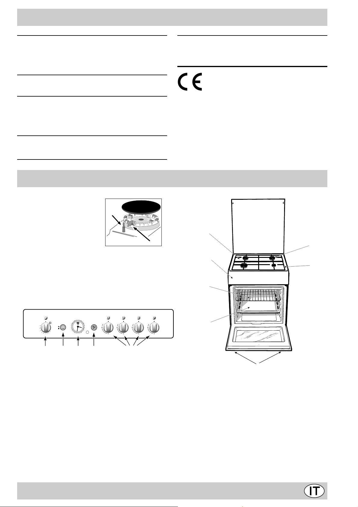
A Piano di contenimento eventuali trabocchi
B Bruciatore a gas
C Dispositivo di accensione istantanea elettronica
D Griglia del piano di lavoro
E Cruscotto
F Piedini regolabili
G Leccarda o piatto di cottur a
H Dispositivo di sicurezza
A
C
B
E
D
K
G
F
K Griglia ripiano del forno
L Accensione elettronica dei bruciatori del piano
M Manopola del forno
N Manopole di comando dei bruciatori a gas del piano
di cottura
O Pulsante per accensione della luce forno e girarrosto
P Orologio con contaminuti Rustico
7
Page 7
Le diverse funzioni presenti nella cucina
F
La selezione delle varie funzioni presenti nella cucina avviene
agendo sui dispositivi ed organi di comando posti sul cruscotto
della stessa.
Le manopole di comando dei bruciatori a gas del piano
di cottura
In corrispondenza di ciascuna delle manopole è indicata, con
un cerchietto pieno •, la posizione del bruciatore a gas da essa
comandato. Per accendere uno dei bruciatori, avvicinare allo
stesso una fiamma o un accenditore.
Premere a fondo e ruotare la manopola corrispondente in sen-
so antiorario fino alla posizione di massimo .Ciascun bruciatore può funzionare al massimo della sua potenza, al minimo, o
con potenze intermedie. In relazione a queste diverse prestazioni, sulla manopola, oltre alla posizione di spento, individuata
dal simbolo • quando questo à posto in corrispondenza della
tacca di riferimento, sono indicate le posizioni di massimo e
di minimo .
Esse si ottengono facendo ruotare la manopola in senso
antiorario dalla posizione di spento.Per spegnere il br uciatore
occorre invece ruotare la manopola in senso orario fino all’arre-
sto (corrispondente di nuovo al simbolo •).
Accensione elettronica dei bruciatori del piano
Alcuni modelli sono dotati di accensione istantanea elettronica
dei bruciatori a gas del piano di cottura: essi sono riconoscibili
per la presenza del dispositivo di accensione (vedi dettaglio C).
Questo dispositivo entra in funzione esercitando una leggera
pressione sul pulsante “L” identificato dal simbolo . Per accendere il bruciatore prescelto è perciò sufficiente premere il
pulsante “L” e contemporaneamente premere a f ondo e ruotare
in senso antiorario la manopola corrispondente fino all’avvenuta
accensione. Per un’accensione immediata è consigliabile
prima premere il pulsante poi ruotare la manopola.
Avvertenza: nel caso di una estinzione accidentale delle
fiamme del bruciatore, chiudere la manopola di comando
e non ritentare l’accensione se non dopo almeno 1 minuto.
Modelli con dispositivo di sicurezza contro fughe di gas
per i bruciatori del piano
Potete identificare questi modelli per la presenza del dispositiv o
(V edi dettaglio H).
Importante: dato che i bruciatori del piano sono dotati di dispositivo di sicurezza, dopo l’accensione del bruciatore, è neces-
sario mantenere premuta la manopola per circa 6 secondi
in modo da consentire il passaggio del gas finché non si scalda
la termocoppia di sicurezza.
Attenzione: Alla prima accensione consigliamo di far funzionare il forno a vuoto per circa mezz’ora con il termostato al massimo, quindi aprite la porta del forno ed aerare il
locale. L’odore che talvolta si a vverte durante questa operazione è dovuto all’ev aporazione delle sostanze usate per
proteggere il forno durante l’intervallo di tempo che intercorre tra la produzione e l’installazione del prodotto.
state cuocendo perchè potreste causare danni allo smalto. Ponete sempre i Vostri recipienti di cottura (pirofile,
pellicole di alluminio, ecc. ecc.) sulla griglia in dotazione
con l’apparecchio appositamente inserita nelle guide del
forno.
La manopola del forno e del grill (M)
E’ il dispositivo che permette di selezionare le diverse funzioni
del forno e di scegliere la temperatura di cottura più idonea ai
cibi da cuocere fra quelle indicate sulla manopola stessa (comprese fra Min e Max).
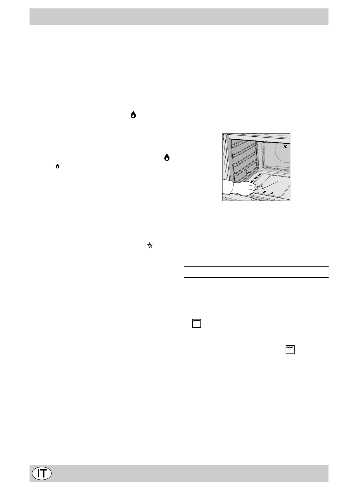
Per accendere il bruciatore forno, a vvicinare al foro “F” una fiamma o un accenditore, contemporaneamente premere a fondo e
ruotare la manopola forno in senso antiorario fino alla posizione
Max.
Dato che la cucina è dotata di dispositivo di sicurezza è
necessario mantenere premuta la manopola per circa 6
secondi in modo da consentire il passaggio del gas. (P er i
modelli dotati di accensione elettronica vedi il relativo paragrafo).
La selezione della temperatura di cottura si ottiene f acendo corrispondere l’indicazione del valore desiderato con il riferimento
posto sul cruscotto; la gamma completa delle temperature
ottenibili è riportata qui sotto.
Min • 150 • 180 • 220 Max
130 140 160 200 250
La temperatura impostata viene automaticamente raggiunta e
mantenuta costante dall’organo di controllo (il termostato) comandato dalla manopola.
Premendo a fondo e ruotando la manopola “ M” fino alla posizio-
ne si mette in funzione il grill a raggi infrarossi, che permette la doratura dei cibi oltre ad essere consigliato per la cottura di
arrosti (braciole, salsicce, roast-beef). Sui modelli con il girarrosto, ruotando la manopola sulla posizione oltre al grill si
mette in moto il motorino girarrosto, che rimane attivato fino a
che il grill è in funzione.
Avvertenza importante: nel caso di una estinzione accidentale delle fiamme dei bruciatori del forno, chiudere la manopola di
comando del bruciatore e non riaccendere il bruciatore prima di
un minuto.
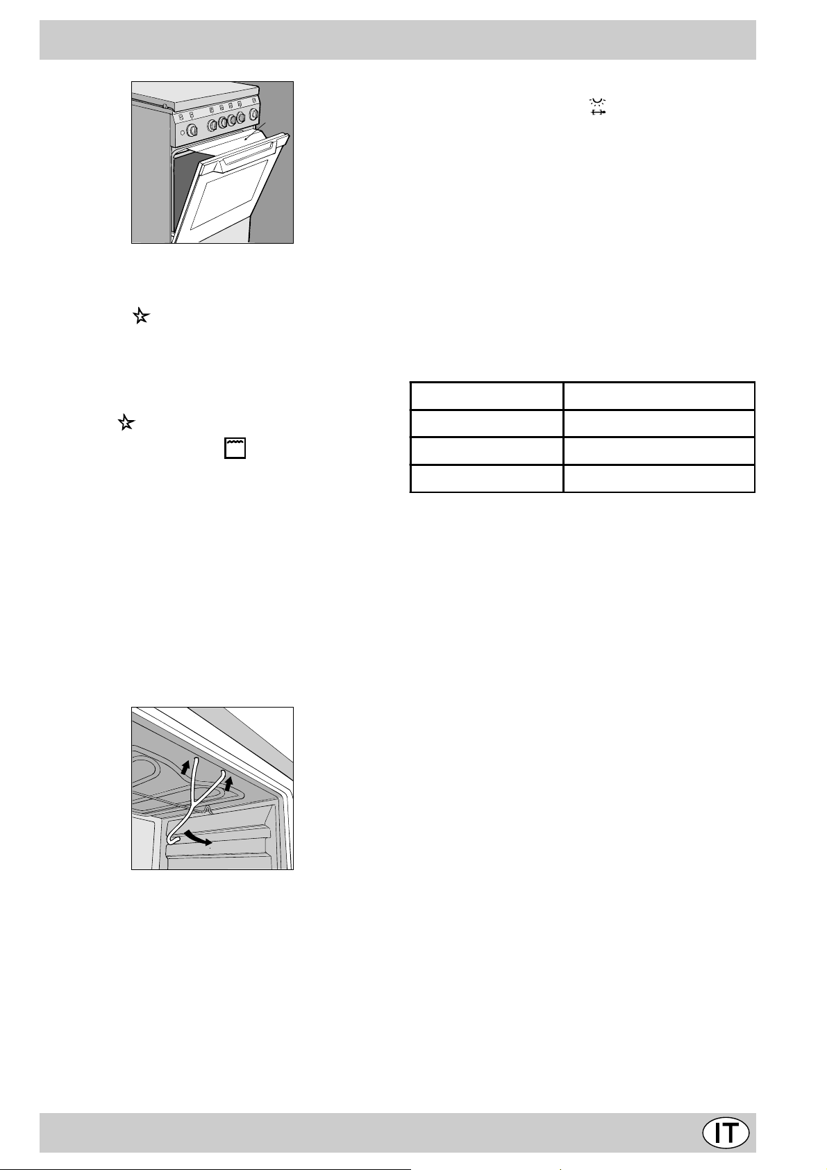
Importante: quando si utilizza il grill è necessario lasciare la porta del forno semiaperta posizionando fra porta e
cruscotto il deflettore “D” che impedisce il surriscaldamento
delle manopole della cucina.
Attenzione: Utilizzare il primo ripiano dal basso solamente
nel caso di cotture con girarrosto (ove presente). Per le
altre cotture non utilizzate mai il primo ripiano dal basso e
non appoggiate mai oggetti sul fondo del forno mentre
8
Page 8
D
Accensione elettronica del bruciatori del forno e del grill
(L)
Per accendere il bruciatore forno premere il pulsante identifica-
to con il simbolo , contemporaneamente premere a fondo e
ruotare la manopola forno in senso antiorario fino alla posizione
Max.
E' necessario tenere premuta la manopola per circa 6 secondi in modo da consentire il passaggio del gas.
Per accendere il bruciatore grill premere il pulsante identificato
con il simbolo , premere a fondo e ruotare la manopola forno
Il pulsante per l’accensione della luce del forno (O)
E’ quello individuato dal simbolo e consente con l’accensione della lampada all’interno del forno, di seguire l’andamento
della cottura senza aprire la porta.
Attenzione
Durante la cottura la porta del forno è calda, impedite che i bambini vi si avvicinino.
Consigli pratici per l’uso dei bruciatori
Al fine di ottenere il massimo rendimento è utile ricordare quanto segue:
• utilizzare recipienti adeguati a ciascun bruciatore (vedere
tabella) alfine di evitare che le fiamme fuoriescano dal fondo
dei recipienti.
• utilizzare solamente recipienti a fondo piatto.
• al momento dell’ebollizione ruotare la manopola fino alla
posizione di minimo.
• utilizzare sempre recipienti con coperchio.
Bruciatore ø Diametro recipienti (cm)
Rapido (R) 24 – 26
in senso orario fino alla posizione (grill).
E' necessario tenere premuta la manopola per circa 6 secondi in modo da consentire il passaggio del gas.
Nel caso di mancanza di elettricità potete accendere manualmente il forno o il grill seguendo le istruzioni riportate nel paragrafo
"La manopola del forno".
Il girarrosto
Per azionare il gir arrosto procedere nel modo seguente:
a) inserire il gancio di sostegno nei due fori posti nella parte
inferiore della protezione grill (posizione A)
b) inserire lo spiedo nel foro posto al centro della parte poste-
riore del forno avendo cura che l’anello di appoggio anteriore dello spiedo sia posizionato correttamente sul gancio di
sostegno (posizione B)
c) azionare il girarrosto premendo il pulsante "O".
1
1
2
Semi Rapido (S) 16 – 20
Ausiliario (A) 10 – 14
N.B. Sui modelli dotati di griglietta di riduzione, quest’ultima dovrà essere utilizzata solo per il bruciatore ausiliario, quando si
utilizzano dei recipienti di diametro inferiore a 12 cm.
3° Vetro
Al fine di ottenere una temperatura più bassa della porta forno
durante il funzionamento, ed un minor consumo di energia, è
disponibile un kit supplementare di protezione. Questo kit dovrebbe essere montato in caso di presenza di bambini piccoli.
Per fare questo è necessario acquistare il kit codice ricambio
053413 presso un rivenditore autorizzato o presso il Servizio
Assistenza Tecnica riportato sulla lista fornita a corredo.
9
Page 9
Orologio con contaminuti Rustico
Come rimettere l’ora corrente
Il forno deve essere collegato elettricamente.
Tirare la manopola e ruotare in senso antiorario fino ad
impostare l’ora esatta.
N.B.: L’orologio funziona elettricamente, quindi in caso di
mancanza di corrente si fermerà per tutta la durata della
mancanza stessa. Dopodichè sarà necessario ripetere
l’operazione di impostazione dell’ora corrente.
Funzione contaminuti
Nel funzionamento contaminuti viene impostato un tempo dal quale comincia un conto alla rovescia. Questa funzione non controlla l’accensione e lo spegnimento del forno, emette solamente un allarme acustico a tempo scaduto.
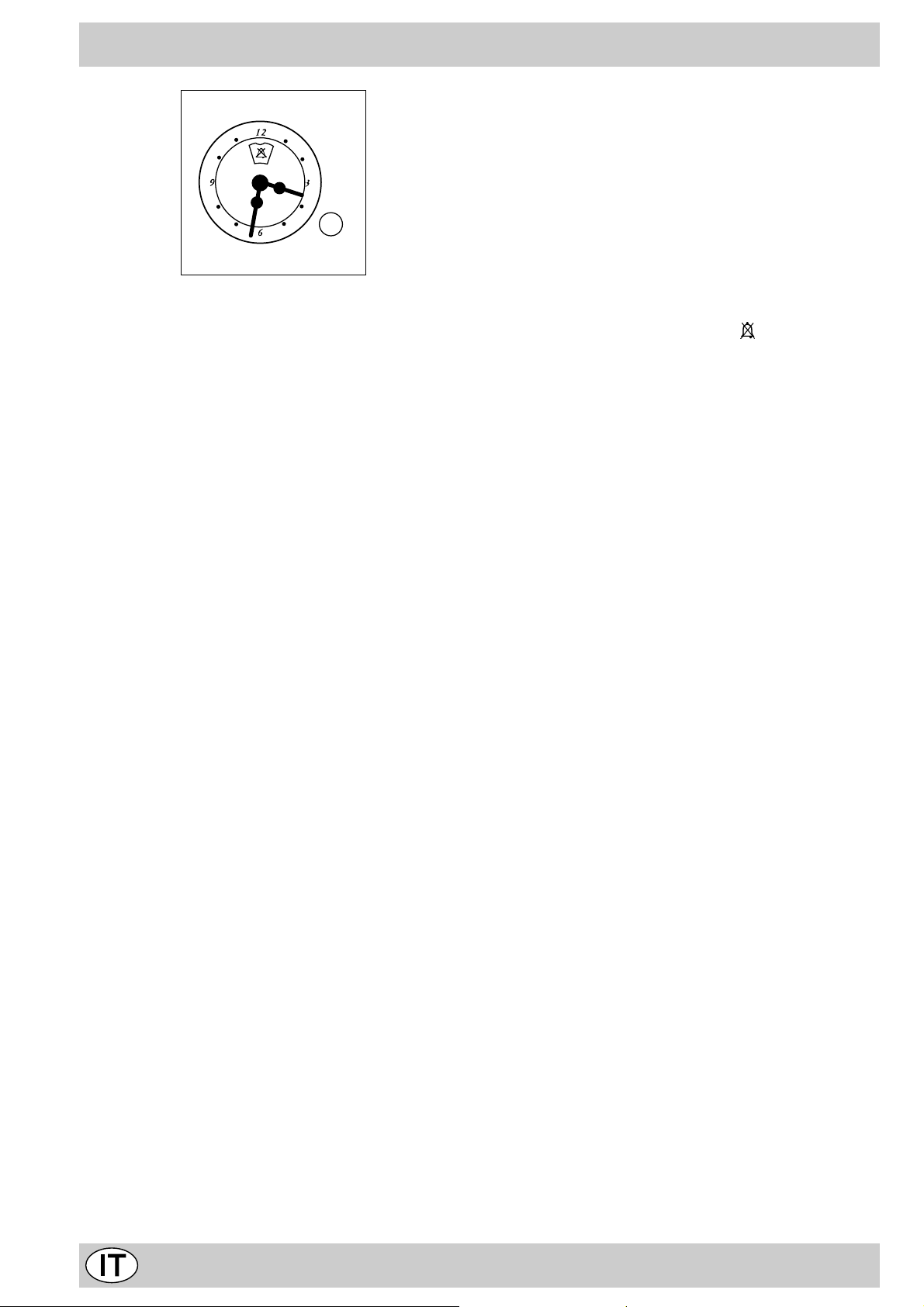
Come impostare il contaminuti
Ruotare la manopola in senso antiorario fino a portare
l’indice sul tempo desiderato (scala interna), visibile attraverso la “finestrella”.
Il conteggio del tempo inizierà immediatamente.
Per interrompere il suono , o per utilizzare la sola funzione
orologio portare l’indice sul simbolo
.
10
Page 10
Consigli pratici per la cottura
Il forno mette a vostra disposizione una vasta gamma di
possibilità che consentono di cuocere ogni cibo nella maniera migliore. Con il tempo potrete sfruttare al meglio questo versatile apparecchio di cottura, pertanto le note riportate di seguito sono solamente delle indicazioni di massima che potrete ampliare con la vostra esperienza personale.
Cottura dei dolci
Nella cottura dei dolci infornate sempre a forno caldo, attendete la fine di preriscaldamento, (circa 15 minuti). Le
temperature sono normalmente nell’intorno di 160°C. Non
aprite la porta durante la cottura, per evitare un abbassamento del dolce. Gli impasti sbattuti non devono essere
troppo fluidi, per non prolungare troppo i tempi di cottura.
In generale:
Dolce troppo secco
La prossima volta imp ostat e una tem pera tura di10°C
superiore e riducete il tempo d i cott ura.
Dolce si abbassa
Usate meno liquido o abbas sate la tem peratur a di
10°C.
Dolce scuro superiormente
Inseritelo ad altez za infer iore, im posta te una
temperatura più bas sa e pro lungate la cot tura.
Buona cottura esterna, ma interno colloso
Usate meno liquido, riduc ete la t emper atur a,
aumentate il tempo d i cottur a.
Dolce non si stacca dallo stampo
Ungete bene lo stampo e cospar getelo anche con un
pò di farina.
Ho cotto su più ripiani e non tutti sono allo stesso
avanzamento di cottura
Impostate una temp eratur a infer iore.
Non necessariament e ripiani ins eriti
contemporaneamente debbono esse re tolti i nsiem e.
Cottura del pesce e della carne
La carne deve pesare almeno 1 Kg. per evitare che si
asciughi troppo. Per le carni bianche, i volatili ed il pesce
utilizzate temperature basse (150°C-175°C). Per le carni
rosse che si vuole siano ben cotte all’esterno conservando all’interno il sugo, è bene iniziare con una temperatura
iniziale alta (200-220°C) per breve tempo, per poi diminuirla successivamente. In generale, più grosso è l’arrosto, più bassa dovrà essere la temperatura e più lungo il
tempo di cottura. Ponete la carne da cuocere al centro
della griglia ed inserite sotto la griglia la leccarda per raccogliere i grassi. Inserite la griglia in modo che il cibo si
trovi al centro del forno. Se volete più calore da sotto, utilizzate i ripiani più bassi. Per ottenere arrosti saporiti
bardate la carne con lardo o pancetta e posizionatela in
modo che sia nella parte superiore.
Manutenzione ordinaria e pulizia della cucina
Prima di ogni operazione disinserire elettricamente
la cucina. Per una lunga durata della cucina è indispen-
sabile eseguire frequentemente una accurata pulizia generale, tenendo presente che:
· per la pulizia non utilizzare apparecchi a vapore
• le par ti smaltate e i pannelli autopulenti, se presenti,
vanno lavate con acqua tiepida senza usare polveri
abrasive e sostanze corrosiv e che potrebbero rovinarle;
• l’interno del forno va pulito, con una certa frequenza,
quando è ancora tiepido usando acqua calda e detersivo, risciacquando ed asciugando poi accuratamente;
• gli spartifiamma vanno lavati frequentemente con acqua calda e detersivo avendo cura di eliminare le
incrostazioni. Nelle cucine dotate di accensione automatica occorre procedere frequentemente ad una accurata pulizia della parte terminale dei dispositivi di
accensione istantanea elettronica e verificare che i fori
di uscita del gas degli spartifiamma non siano ostruiti;
• l’acciaio inox può rimanere macchiato se rimane a contatto per lungo tempo con acqua fortemente calcarea
o con detergenti aggressivi (contenenti fosforo). Si con-
siglia di sciacquare abbondantemente ed asciugare
dopo la pulizia. E’ inoltre opportuno asciugare eventuali trabocchi d’acqua;
N.B.: evitare di chiudere il coper chio fino a che i bruciatori gas sono ancora caldi.
Importante: controllare periodicamente lo stato di con-
servazione del tubo flessibile di collegamento gas e sostituirlo non appena presenta qualche anomalia; è
consigliabile la sostituzione annuale.
Sostituzione della lampada nel vano forno
• T ogliere l’alimentazione alla cucina tramite l’interruttore omnipolare utilizzato per il collegamento della cucina all’impianto elettrico, o scollegare la spina, se accessibile;
• Svitare il coperchio in vetro del portalampada;
• Svitare la lampada e sostituirla con una resistente ad
alta temperatura (300°C) con queste caratteristiche:
- T ensione 230V
- Potenza 25W
- Attacco E14
• Rimontare il coperchio in vetro e ridate alimentazione
al forno.
11
Page 11
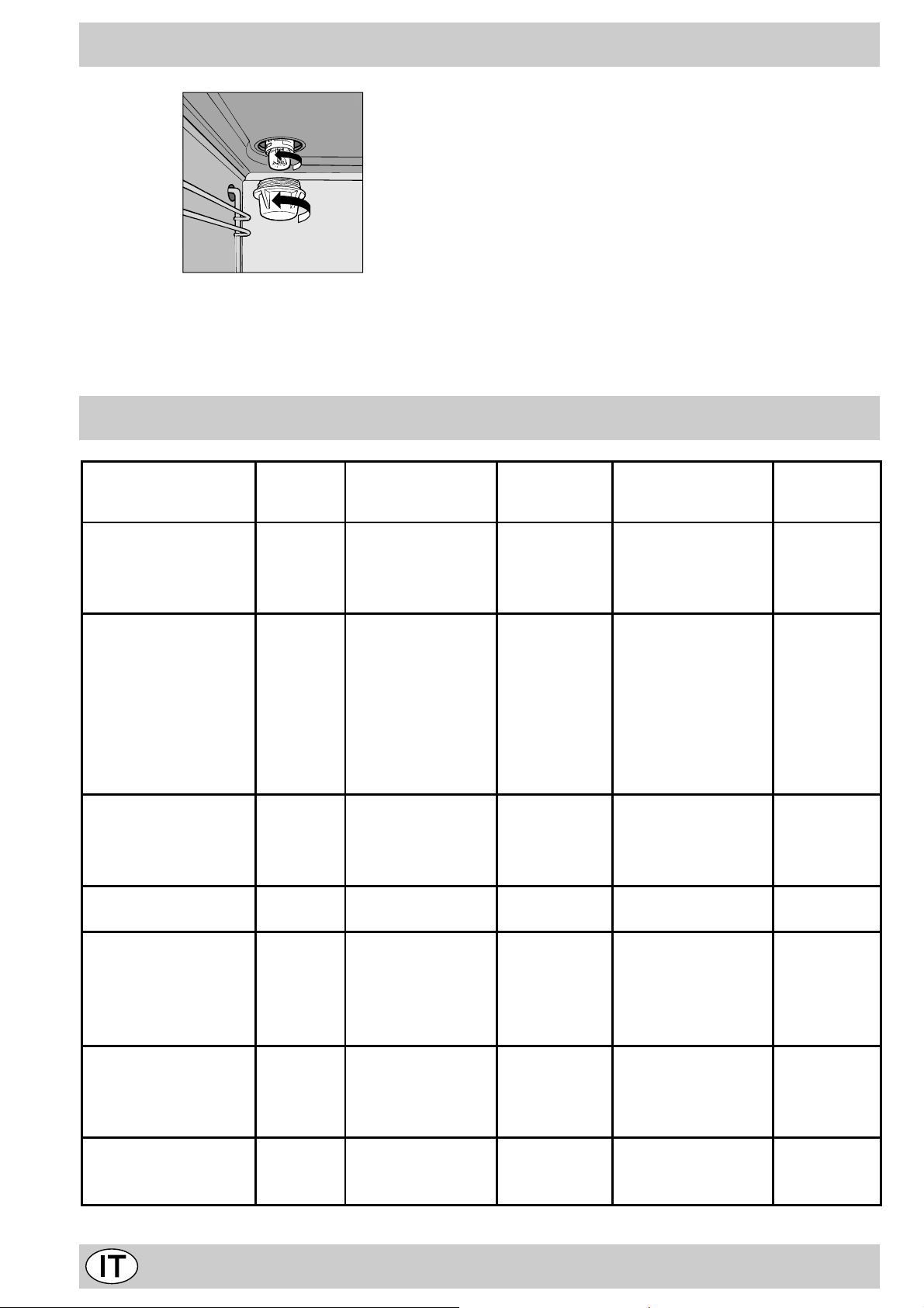
Ingrassaggio dei rubinetti
Con il tempo può verificarsi il caso di un rubinetto che si
blocchi o presenti difficoltà nella rotazione, pertanto sarà
necessario provvedere alla sostituzione del rubinetto stesso.
N.B.: Questa operazione deve essere effettuata da un
tecnico autorizzato dal costruttore.
Consigli pratici per la cottura al forno
Cibo da cucinare Peso
(Kg)
Pasta
Lasagne 2,5 3 210 - 75-80
Cannelloni 2,5 3 210 - 75-80
Tagliatelle 2,5 3 210 - 75-80
Carni
Vitello 1,7 3 230 - 85-90
Pollo 1,5 3 220 - 110-115
Tacchino 3,0 3 MAX - 95-100
Anatra 1,8 3 230 - 120-125
Coniglio 2 3 230 - 105-110
Maiale 2,1 3 230 - 100- 110
Agnello 1,8 3 230 - 90-95
Pesci
Sgombri 1,1 3 210-230 - 55-60
Dentice 1,5 3 210-230 - 60-65
Trota al cartoccio 1,0 3 210-230 - 40-45
Pizza
Napoletana 1,0 3 MAX 15 30-35
Torte
Biscotti 0,5 3 180 15 30-3 5
Crostata 1,1 3 180 15 30-3 5
Torta al cioccolato 1 3 200 15 45-50
Torta lievitata 1 3 200 15 50-55
Cottura al grill
Toast n. ° 4 4 10
Braciole di maiale 1,5 4 30
Sgombri 1,1 4 35
Cottura al girarrosto
Vitello allo spiedo 1 2 80
Pollo allo spiedo 2 2 90
Nota: i tempi di cottura so no pura mente i ndicat ivi e poss ono va riare i n base a i gusti persona li.
Posizione cottura
ripiani dal basso
Temperatura
(°C)
Tempo di
preriscaldamento
(minuti)
Tempo di
cottura
(minuti)
12
Page 12

Important safety warnings
T o maintain the EFFICIENCY and SAFETY of this appliance, we recommend:
• call only the Service Centers authorized by the manufacturer
• always use original Spare Parts
1 These instructions are only for those countries whose
symbols appear in the booklet and on the matriculation
plate of the appliance.
2 This appliance is intended for non-professional use
within the home.
3 This owner's manual is f or a class 1 appliance (installed
independently) or class 2 - sub-class 1 appliances
(installed between two cabinets).
4 Before using the appliance, read the instructions in this
owner’ s manual carefull y since y ou should find all the
instruction you require to ensure safe installation, use
and maintenance. Always keep this owner’s manual
close to hand since you may need to refer to it in the
future.
5 When you have removed the packing, check that the
appliance is not damaged. If you have any doubts, do not
use the appliance, contact your nearest Ariston Service
Centre. Ne ver lea ve the packing components (plastic bags ,
foamed polystyrene, nails, etc.) within the reach of children
since they are a source of potential danger.
6 The appliance must be installed only by a qualified person in
compliance with the instructions provided. The manufacturer
declines all responsibility for improper installation which may
harm persons and animals and damage property .
7 The electrical safety of this appliance can only be guaranteed
if the cooker is correctly and efficiently earthed, in compliance
with current regulations on electrical safety. Alwa ys ensure
that the earthing is efficient; if you hav e any doubts call in a
qualified electrician to check the system. The man ufacturer
declines all responsibility for damage resulting from a system
which has not been earthed.
8 Before plugging the appliance into the mains, chec k that the
specifications indicated on the date plate correspond to those
of the electrical and gas mains system of your home.
9 Check that the electrical capacity of the system and sockets
will support the maximum power of the hob, as indicated on
the data plate. If you have any doubts, call in a qualified
technician.
10 An omnipolar switch with a contact opening of at least 3 mm
or more, is required for the installation.
11 If the sock et and hob plug are not compatible, have the sock et
replaced with a suitable model by a qualified technician who
should also check that the cross-section of the sock et cable
is suited to the power absorbed by the appliance . The use of
adaptors, multiple sockets and/or extensions, is not
recommended. If their use can not be avoided, remember to
use only single or multiple adapters and extensions which
comply with current safety regulations. In these cases, never
exceed the maximum current capacity indicated on the single
adaptor or extension and the maximum pow er indicated on
the multiple adapter.
12 Do not leave the appliance plugged in if it is not in use. Switch
off the main switch and gas supply when you are not using
the cooker .
13 The openings and slots used for v entilation and dispersion
of heat on the rear and below the control panel must nev er
be covered.
14 The user must not replace the supply cable of this appliance.
Always call an after-sales servicing centre authorised by the
manufacturer in the case of cable damage or replacement.
15 This appliance must be used for the purpose f or which it was
expressly designed. Any other use (e.g. heating rooms) is
considered to be improper and consequently dangerous. The
manufacturer declines all responsibility f or damage resulting
from improper and irresponsible use.
16 A number of fundamental rules must be followed when using
electrical appliances. The following are of particular
importance:
· do not touch the appliance when your hands or feet are
wet
· do not use the appliance barefooted
· never allow the Mains Cable to be stretched, pulled or
damaged if the Cooker is moved f or cleaning etc. Do not
use the cooker if the Mains Cable is damaged, consult a
qualified electrician.
· do not allow the cooker to be used unsuper vised by
children or persons unfamiliar with it.
17 Alwa ys switch off the electrical supply to the cooker and allow
it to cool down before carrying out any cleaning operations
etc.
18 If you are no longer using an appliance of this type, remember
to make it unserviceable by unplugging the appliance from
the mains and cutting the supply cable. Also make all
potentially dangerous parts of the appliance, safe, above all
for children who could play with the appliance .
19 T o av oid accidental spillage do not use cookware with uneven
or deformed bottoms on the burners or on the electric plates.
20 Special care should be taken when using chip pans etc. in
order to avoid splashing or spillage of hot oil. They should not
be used unattended since overheated oil ma y boil over and
could also ignite.
21 Parts of this appliance, cooking surfaces, retain heat for
considerable periods after switching off. Care should,
therefore, be tak en when touching these areas before the y
have completely cooled do wn.
22 Never use flammable liquids such as alcohol or gasoline,
etc. near the appliance when it is in use.
23 When using small electric appliances near the hob, keep the
supply cord away from the hot parts.
24 Make sure the knobs are in the “•”/”¡” position when the
appliance is not in use.
25 When the appliance is in use, the heating elements and
some parts of the oven door become extremely hot.
Make sure you don't touch them and keep children well
away.
26 Gas units need a regular air replacement f or a correct
functioning. Make sure that the requirements requested
in the “Positioning” paragraph are all observed in the
owner’ s manual.
27 If the cooker is placed on a pedestal, take the necessary
precautions to prevent the same from sliding off the pedestal
itself.
13
Page 13
Installation
The following instructions should be read by a qualified technician
to ensure that the appliance is installed, regulated and technically
serviced correctly in compliance with current regulations.
Important: remember to unplug the appliance from the
mains before regulating the appliance or carrying out any
maintenance work.
Positioning
Important: This unit may be installed and used only in perma-
nently ventilated rooms in accordance with current National
Regulations. The f ollowing requirements must be observed:
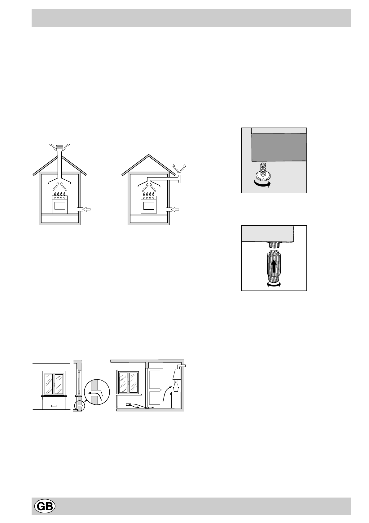
a) The room must be equipped with an exhaust system that
vents the combustion fumes to the outside. It may consist of
a hood or an electric fan that automatically starts each time
the appliance is turned on.
therefore, be installed or stored in rooms or storage areas
that are below ground level (cellars, etc.) whether they are
partially or completely full. It is a good idea to keep only the
cylinder being used in the room, positioned so that it is not
subject to heat produced by external sources (ovens, fireplaces, stoves , etc. ) which are able to increase the temperature of the cylinder above 50°C .
Levelling your appliance (only on a f ew models)
Your cooker is supplied with feet for levelling the appliance. If
necessary , these feet can be scre w ed into the housings in the
corners of the cooker base.
Mounting the legs (only on a few models)
Press-fit legs are supplied which fit under the base of your cooker .
A Flue or Branched Flue System Directly to the outside
(only for cooking appliances)
b)
The room must also have a system to permit proper air circulation, needed for combustion to occur normally. The flow of
air needed for combustion must not be less than 2 m3/h per
kW of installed power. The air circulation system may take air
directly from the outside by means of a pipe with an inner
cross section of at least 100 cm2; the opening must not be
able to be accidentally blocked. For those appliances not
equipped with a safety device for accidental flame loss, the
ventilation apertures must be increased by 100%, with the
minimum being 200cm2 (Fig. A). The system can also provide
the air needed for combustion b y indirect means , i.e . from adjacent rooms fitted with air circulation tubes as described above.
However, these rooms must not be common rooms or bedrooms. (Fig. B).
Detail A Adjacent Room to be
A
Examples of Ventilation Increased Opening Between
Openings Comburent Air Door and Floor
Room Ventilated
Fig. A Fig. B
c) Intensive and prolonged use of the appliance may result in
the need for supplemental air circulation, e.g. opening windows or increasing mechanical venting (if present).
d) Liquified petroleum gas is heavier than the air and, therefore,
settles downwards. Thus, rooms containing LPG cylinders
must also be equipped with apertures to the outside for ventilation of gas in the case of leaks. LPG cylinders must not,
Installation of the cooker
The appliance can be installed next to cabinets, provided the
height does not exceed that of the hob. If the cooker is placed
touching walls or sides of neighbouring cabinets, these must be
capable of withstanding a temperature rise of 50°C above room
temperature. For a correct installation of the cooker the following
precautions must be followed:
a) The cooker may be located in a kitchen, a kitonen/diner or
bed sitting room, but not in a bathroom or shower room.
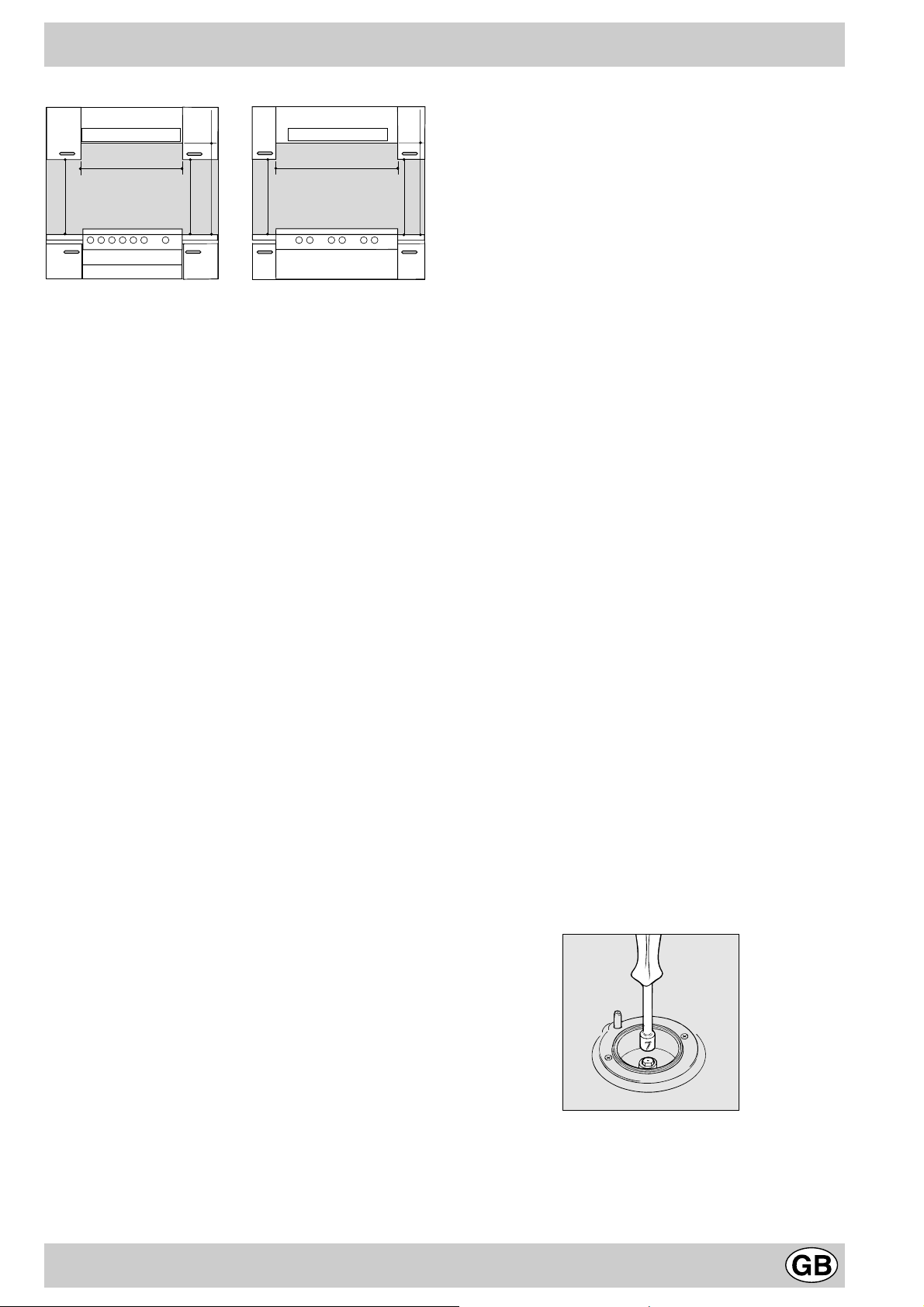
b) The furniture units next to the cooker, that is higher than the
working boards, must be placed at least 110mm from the
edge of the board. Curtains must not be fitted immediately
behind the cooker or within 110 mm. of the sides of the cooker.
c) The hoods must be installed according to the requirements
in the hood handbook.
d) Wall cabinets may be fitted in line with the sides of the base
units, providing that the lower edge of the wa ll cabinet is a
minimum of 420 mm. above the worktop. The minimum
distance combustible material kitchen units can be fitted
directly above the worktop is 700 mm.
14
Page 14
HOOD
Min. mm.
900
mm. with hood
mm. without hood
420
650
700
Min. mm.
min.
min.
mm.
420
Min.
HOOD
Min. mm.
600
mm. with hood
420
650
Min. mm.
min.
mm. without hood
700
min.
mm.
420
Min.
e) The wall in contact with the back of the cooker must be of
flameproof material.
Connecting the gas
The appliance should be connected to the mains or to a gas
cylinder in compliance with current directives. Before making
the connection, check that the cooker is regulated for the gas
supply you are using. If not, follow the instructions indicated in
the paragraph “Adapting to different types of gas”. On some
models the gas supply can be connected on the left or on the
right, as necessary; to change the connection, reverse the position
of the hose holder with that of the cap and replace replace the
gasket (supplied with the appliance). When using liquid gas from
a cylinder, install a pressure regulator which complies with current
directive.
Important: check that the supply pressure complies with the
values indicated in table 1 “Characteristics of the burners and
nozzles” since this will ensure safe operation, correct
consumption and ensure a longer life to your appliance.
Connection with hose
Make the connection using a gas hose complying with the the
characteristics provided in current directive. The internal diameter
of the pipe used is as follows:
- 8mm for liquid gas;
- 13mm for methane gas.
When installing the hose, remember to take the following
precautions:
• No part of the hose should touch parts whose temperature
exceeds 50°C;
• The length of the hose should be less than 1500 mm;
• The hose should not be subject to twisting or pulling, and
should not have bends or kinks.
• The hose should not touch objects with sharp edges, any
moving parts, and it should not be crushed;
• The full length of the hose should be easy to inspect in order
to check its condition;
Check that the hose fits firmly into place at the two ends and fix
it with clamps complying to current directive.If any of the abov e
recommendations can not be adopted, flexible metal pipes should
be used.
Should the cooker be installed according to the conditions of
Class 2, subdivision 1, only a flexible metal pipe which is in
compliance with current safety standards should be used to make
the connection to the gas mains.
Only pipes and gaskets complying with current directives. The
full length of the pipe must not exceed 2000 mm.
Tight control
Important: when installation has been completed, check the
pipe fitting for leaks with a soapy solution. Never use a flame.
Once the connection has been made, ensure that the flexible
metal tube does not touch any moving parts and is not crushed.
Connecting the supply cable to the mains
Install a normalised plug corresponding to the load indicated on
the data plate. When connecting the cable directly to the mains,
install an omnipolar circuit-breaker with a minimum contact
opening of 3 mm between the appliance and the mains. The
omnipolar circuit breaker should be sized according to the load
and should comply with current regulations (the earth wire should
not be interrupted by the circuit breaker).
The supply cable should be positioned so that it does not reach
a temperature of more than 50°C with respect to the room temperature, along its length. Before making the connection, check
that:
• the limiter valve and the home system can support the
appliance load (see data plate);
• the mains is properly earthed in compliance with current
directives and regulations;
• there is easy access to the socket and omnipolar circuit
breaker , once the hob has been installed.
N.B: never use reducers, adaptors or shunts since they can
cause heating or burning.
Adapting the cooker to different types of gas
In order to adapt the cooker to a different type of gas with respect
to the gas for which it was produced (indicated on the label
attached to the lid), follow these steps:
a) replace the hose holder mounted on the appliance with that
supplied in the bag of “cooker accessories”.
Important: the hose holder for liquid gas is marked 8, the hose
holder for methane gas is marked 13. Always fit the sealing
gasket.
b) Replacing the burner nozzles on the hob:
• remove the grids and slide the burners from their housings;
• unscrew the nozzles using a 7 mm socket spanner, and
replace them with nozzles for the new type of gas (see tab le
1 “Burner and nozzle characteristics”).
• replace all the components by repeating the steps in reverse
order.
Connecting a flexible jointless stainless steel pipe to a
threaded attachment
Remove the hose holder fitted on the appliance. The gas supply
pipe fitting is a threaded 1/2 gas cylindrical male attachment.
c) Minimum regulation of the hob burners:
•
turn the tap to minimum;
• remove the knob and adjust the regulation screw, which is
positioned in or next to the tap pin, until the flame is small but
steady .
15
Page 15

N.B.: in the case of liquid gas, the regulation screw must be
V
4
m
m
screwed in to the bottom.
• check that the flame does not turn off when you turn the tap
quickly from high to low .
d) Regulating the primary air of the burners:
The primary air of the burners requires no regulation.
Adapting the gas oven to different types of gas
a) Replacing the oven burner nozzle:
• remove the warming drawer;
• in the case of models without warming drawer , remov e the
panel “P” as indicated in Fig. A. Open the door, release the
two top inserts by pressing them downwards, and then the
two bottom inserts by pressing them upwards.
• remove the sliding protection “A”;
• remove the two screws to dismount the protection “B”; (see
Fig. B);
• remove the screw and then the ov en burner “V”(see Fig. C).
Remove the ov en door to facilitate this operation.
• unscrew the oven burner nozzle using the special socket
spanner for the nozzles (see Fig. D), or better still a 7 mm
socket spanner, and replace it with a nozzle suited to the
new type of gas (see table 1).
• check that the burner does not turn off when you turn the
knob from Max to Min and and when you open and close
the oven door quickly.
Adapting the gas grill to different types of gas
Replacing the nozzle of the grill burner:
• remove the screw and then slide out the grill burner “V”
(see Fig. E);
• unscrew the grill burner nozzle using the special socket
spanner for the nozzles (see Fig. F) or better still a 7 mm
socket spanner; replace the nozzle with a nozzle f or the new
type of gas (see table 1).
B
A
Fig. A Fig. B
V
Fig. C Fig. D
b) Minimum regulation of the gas oven burner with thermostat
(see fig.):
• light the burner as described in the paragraph “the oven knob”
of the instruction booklet.
• turn the knob to Max for about 10 minutes and then turn the
knob to the Min setting;
• remove the knob;
• regulate the screw positioned outside the thermostat pin
until the flame is small but steady .
N.B.: in the case of liquid gas, the regulation screw must
be screwed in to the bottom.
I
Fig. E Fig. F
Important: when mounting the grill burner check that there is a
space of at least 4 mm between the security thermocouple (if
installed) and the burner.
Important
On completion of the operation, replace the old rating sticker
with one indicating the new type of gas used. This sticker is
available from our Service Centres.
Note
Should the pressure of the gas used be different (or vary) from
the recommended pressure, it is necessary to fit a suitable
pressure regulator onto the inlet pipe in compliance with current
National Regulations relative to “regulators f or channelled gas”.
16
Page 16

Burner and nozzle characteristics
Table 1 Liquid Ga s Natural G as
Burner Diam eter
(mm)
Thermal Power
kW (p.c.s.*)
By-Pass
1/100
Nozzle
1/100
Flow*
g/h
Nozzle
1/100
Flow*
l/h
Nozzle
1/100
Flow*
Nominal Reduced (mm) (mm) *** ** (mm) (mm)
Fast
(Large)(R)
Semi Fast
(Medium)(S)
Auxiliary
(Small)(A)
100 3.00 0.7 41 86 218 214 116 286 143 286
75 1.90 0.4 30 70 138 136 106 181 118 181
55 1.00 0.4 30 50 73 71 79 95 80 95
Oven - 3.0 2 1.0 49 85 219 216 132 288 148 288
Grill - 2.50 - - 80 182 179 122 227 139 227
Supply
Pressures
Nominal (mbar)
Minimum (mbar)
Maximum (mbar)
28-30
20
35
37
25
45
20
17
25
13
6,5
18
* At 15°C and 1013 mbar- dry gas
** Propane P.C.S . = 50,37 MJ/Kg
*** Butane P.C.S. = 49,47 MJ/Kg
Natural P.C.S . = 37,78 MJ/m
3
l/h
Table1 (For Hungary)
(only model C 647 G R)
Burner By-pass
1/100 (mm)
Thermal
power kW
G 20 G 25.1 G 30
Nozzle
1/100 (mm)
Thermal
power kW
Nozzle
1/100 (mm)
Thermal
power kW
1/100 (mm)
Nozzle
Fast (R) 41 2,90 116 2,30 116 2, 60 86
Semi Fast (S) 30 1,90 106 1,50 106 1,70 70
Auxiliary (A) 30 1,00 79 0,70 79 0,90 50
Oven 49 3,20 132 2,50 132 3,00 85
Grill 49 2,40 122 1,90 122 2,40 80
Supply pressures 25 mbar 25 mbar 30 mbar
At 15°C and 1013 mbar-dr y gas
P.C.I. G20 35,9 MJ/m
S
S
R
A
3
P.C.I. G30 122,8 MJ/m
P.C.I. G25.1 30,9 MJ/m
3
3
C 647 G...R
17
Page 17

Inner dimensions of the oven:
F
A
E
K
G
D
B
Technical characteristics
Width: 40,5 cm
Depth: 39,5 cm
Height: 32 cm
Inner Volume of the Oven:
Innder dimensions of the plate plate warmer:
Width: 43 cm
Depth: 43 cm
Height: 8 cm
Voltage and Frequency of Po wer Supply:
see data plate
Burners:
adaptable for use with all the types of gas indicated on
the data plate
The cooker with gas oven
H
52 lt
This appliance conforms with the following Eur opean
Economic Community directives:
- 73/23/EEC of 19/02/73 (Low Voltage) and subsequent
modifications;
- 89/336/EEC of 03/05/89 (Electromagnetic
Compatibility) and subsequent modifications;
- 90/396/EEC of 29/06/90 (Gas) and subsequent
modifications (only for models which use gas);
- 93/68/EEC of 22/07/93 and subsequent modifications.
MIN
150
180
M
1
0
MAX
220
9
O
12
3
6
PL
N
A Tray for Catching Overflo ws
B Gas Burner
C Instantaneous Electronic Lighting Device
D Top Grate
E Control Panel
F Adjustable Feet or Legs
G Dripping Pan or Baking Sheet
C
H Safety Device
K Oven Rack
L Electronic Lighting for Hob Burners
M Oven and Grill Control Knob
N Control Knobs for Gas Burners on Hob
O Button for Oven and Rotisserie Light
P Country Style Clock and Timer
18
Page 18

The different functions and uses of the oven
F
D
The various functions included in the cooker are selected by
operating the control devices located on the cooker control panel.
Control Knobs for the Gas Burners on the Hob
The position of the gas burner controlled by each one of the
knobs is shown by a symbol of a solid ring:•. T o light one of the
burners, hold a lighted match or lighter near the burner. Press
down and turn the corresponding knob in the counter-clockwise
direction to the maximum setting. Each burner can be operated at its maximum, minimum or intermediate power . Shown
on the knob are the different symbols for off • (the knob is on this
setting when the symbol lines up with the reference mark on the
control panel), for maximum and minimum .
To obtain these settings, turn the knob counter-clockwise with
respect to the off position. T o turn off the burner , turn the knob
clockwise until it stops (corresponding again with the • symbol).
Electronic Lighting of the Hob Burners
Some models are equipped with instant electronic lighting of the
gas burners located on the hob, which can be identified by the
presence of an igniter device (see detail C). This de vice is activated by lighting pressing on the “L” button, identified by the
symbol. T o turn on a burner, simply press the “L” button and
then press while, at the same time, pressing in and turning the
control knob for the burner in the anticlockwise direction until the
burner lights. To light the burner immediately, it is recom-
mended that the button be pressed first and then the knob
turned.
Caution: If the burner accidentally goes out, turn off the
burner using the knob and wait at least one minute before
relighting.
Models with Hob Gas Burner Safety Devices to Prevent
Leaks
These models can be identified by the presence of the device
itself (see detail H).
Important: Since the hob burners are equipped with a safety
device, y ou must hold the control knob in for about 6 seconds
after the burner has been lighted to allow the gas to pass until
the safety thermocouple has heated.
Notice: The first time y ou use your appliance, we recommend that you set the thermostat to the highest setting
and leave the ov en on f or about half an hour with nothing
in it, with the oven door shut. Then, open the oven door
and let the room air. The odour that is often detected during this initial use is due to the evaporation of substances
used to protect the oven during storage and until it is installed.
The oven and grill knob (M)
This knob is used to select the different functions of the oven
and choose the right cooking temperature for the food to be
prepared in the oven among the temperatures shown on the
knob (from Min to Max).
T o light the oven b urner, hold a lighted match or lighter near hole
“F” and turn the oven knob counter anti cloc kwise up to the Max
position.
The models equipped with a safety device on oven b urner,
the knob must be kept pressed in for about 6 seconds to
activate the flame failure device. (For the models pr ovided
with electronic lighting see the relative paragraph).
The cooking temperature is selected by matching the desired
temperature with the permanent reference on the panel; the
complete range of temperatures is shown belo w:
Min • 150 • 180 • 220 Max
130 140 160 200 250
The selected temperature is reached automatically and it is kept
constant by the knob-controlled thermostat.
T o use the grill, turn the knob clockwise till to setting , after
holding a lighted match or a lighter close to the grill burner.
In the grill burner equipped with a safety device, the knob
must be held pressed in for about 6 seconds in order to
activate the flame failure device (for the model provided
with electronic lighting see the relative paragraph). In this
way the infrared r ay comes on for bro wning the food or cooking
roast, chops, sausages, roast-beef, etc.; for grill cooking, place a
drip-pan under the grill to catch the grease.
Important: when using the grill, the oven door must be left
partly open by positioning the deflector “D” between door
and panel to prevent the cook er knobs from ov erheating.
Attention: Only use the bottom shelf of the oven when using
the rotisserie to cook (where present). For all other types of
cooking, never use the bottom shelf and ne ver place anything
on the bottom of the oven when it is in operation because this
could damage the enamel. Always place your cookware (dishes,
aluminium foil, etc. etc.) on the grate provided with the appliance
inserted especially along the oven guides.
Oven and grill electronic lighting device (L)
Some models are equipped with electronic lighting device on
oven and grill.
To light the oven gas burner press in the botton marked by
the symbol , press deeply and turn the oven knob clockwise,
19
Page 19

till to the position “Max”.
It is necessary to hold pressed in the knob for about 4
seconds in order to activate the flame failure device.
T o light on the grill burner press in the bottom marked b y the
symbol , press deeply and turn the ov en knob counter clock
wise till to the position (grill).
It is necessary to hold pressed in the knob for about 4
seconds in order to activate the flame failure device.
In case of lack of electricity light the oven or g rill manuall, following
the instruction of “the ov en knob paragraph”.
The rotisserie
When using the rotisserie act in this way:
a) fit supporting hook into the two holes in the lower side of the
grill protection (position A);
b) fit the spit into the hole in the centre of the back of the oven,
making sure that the fore clasping link of the spit is correctly
positioned on the supporting hook (position B);
c) start up the rotisserie by pressing the botton "O".
Oven light button (O)
This is marked by the symbol and switchs on the light
inside the oven so that you can control the cooking without
opening the door.
Attention
Avoid the children touch the oven door because it is very hot
during the cooking.
Practical advice for burner use
In order to get the maximum yield it is important to remember
the following:
· Use appropriate cookware for each burner (see table) so as
to avoid flames ov ershooting the edges.
· At boiling point turn the knob to minimum.
· Use cookware with lids.
· Always use cookware with flat bottoms.
Burner ø Cookware diameter (cm)
Fast (R) 24 - 26
Semi Fast (S) 16 - 20
Auxiliary (A) 10 - 14
Country Style Clock and Timer
How to Set the Current Time
The oven must be connected to the po w er supply
Pull and turn the knob in the counter-clockwise direction
to set the time.
N.B.: The clock is electric. Therefore, in the event of a
power outage, the clock will stop for the entire time the
oven remains without power . When the power comes back
on, the clock must be reset to the current time
N.B. On the models supplied with a reducer shelf, remember
that this should be used only for the auxiliary burner when you
use casserole dishes with a diameter under 12 cm.
3rd Oven Glass
In order to further decrease the temperature of the oven door
and reduce energy consumption, a supplemental kit has been
made available . This kit should be installed if the oven is used in
the presence of small children. To install the protective glass for
the oven door (code 053413), contact your nearest Merloni
Eletrodomestici Service Centre indicated on the list provided
with the appliance.
Timer Feature
The timer operates by counting down a given period of
time. This feature does not, howev er, turn the oven on or
off. It merely emits an acoustical alarm when the time has
run out.
How to Set the Timer
Turn the knob in the counter-clockwise direction until the
indicator is set on the length of time desired (using the
inside numbers). The time is clearly visible through the
transparent window on the indicator itself.
The timer will begin to count down immediately.
To turn off the buzzer, or to use only the clock, set the
indicator on the symbol.
20
Page 20

Cooking advice
The oven off ers a wide range of alternatives which allow
you to cook any type of food in the best possib le wa y . With
time you will learn to make the best use of this versatile
cooking appliance and the following directions are only a
guideline which may be varied according to your o wn personal experience.
I used more than one level and they are not all at
the same cooking point
Use a lower temperature setting. It is not necessary to
remove the food from all the racks at the same time.
Baking cakes
The oven should alwa ys be warm before putting in cak es
wait till the end of preheating (about 15 min.). Cake-baking
temperatures are normally around 160°C. Do not open
the oven door during the baking process as this could
cause the cake to sink.
Beaten cake mixtures should not be too soft as this could
considerably lengthen cooking times. In general:
Pastry is too dry
Increase the temperature by 10°C and reduce the
cooking time.
Pastry dropped
Use less liquid or lower the temperature by 10°C.
Pastry is too da rk on t op
Place it on a lower rack, lower the temperature, and
increase the cooking t ime.
Cooked well on the inside but sticky on the outside
Cooking fish and meat
Meat must weigh at least one Kg. to stop it becoming too
dry. When cooking white meat, fowl and fish use low
temperatures. (150°C-175°C). When red meat must be
superficially well-cooked but succulent inside, it is
advisable to start with a high temperature (200-220°C)
for a short time, and then to reduce it at a later point.
Generally speaking, the more meat there is, the lower the
temperature and the longer the cooking time should
be.Place the meat in the centre of the grid and put a spilltray underneath to catch grease drips. Insert the grid so
that it is in the middle of the oven. If more heat from below
is required, use the 1° bottom shelf. For tastier roasts,
wrap the meat with bacon rashers or dot the meat with
lard and place it in the upper part of the oven. When some
types of food are cooked in the ventilated oven (duck,
rabbit, large fowl) they become too dr y; in these cases,
better results are obtained using the combined oven.
Use less liquid, l ower the temperature, and increas e the
cooking time.
The pastry sticks to the pan
Grease the pan well and sprinkl e it wit h a dusting of
flour.
21
Page 21

Cooker routine maintenance and cleaning
Before each operation, disconnect the cooker from
the electricity .To assure the long life of the cooker , it must
be thoroughly cleaned frequently, keeping in mind that:
· Do not use steam equipment to clean the appliance.
· the enamelled parts and the self-cleaning panels are
washed with warm water without using any abrasive
powders or corrosive substances which could ruin
them;
· the inside of the oven should be cleaned fairly often
while it is still warm using warm water and detergent,
followed b y careful rinsing and drying;
· the flame spreaders should be washed frequently with
hot water and detergent taking care to eliminate any
scale; in cook ers equipped with automatic lighting, the
terminal part of the electronic instant lighting devices
should be cleaned frequently and the gas outlet holes
of the flame spreaders should be checked to make
sure they are free of any obstructions;
· Stainless steel may become marked if it comes into
contact with very hard water or harsh detergents
(containing phosphorous) for long periods of time. After
cleaning, it is advisable to rinse thoroughly and dry. It
is also recommended to dry any water drops;
N.B: avoid closing the cover while the gas burners are
still warm.
Important: per iodically check the wear of the gas hose
and substitute it if there are any defects; we recommended
changing it every year.
Replacing the oven lamp
· Unplug the oven from the mains;
· Remove the glass cover of the lamp-holder;
· Remove the lamp and replace with a lamp resistant to
high temperatures (300°C) with the following
characteristics::
- V oltage 230V
- Wattage 25W
- Type E14
· Replace the glass cover and reconnect the oven to
the mains.
Greasing the Taps
The taps may jam in time or they ma y become difficult to
turn. If so , the tap itself must be replaced.
N.B.: This operation m ust be performed by a technician
authorised by the manufacturer .
22
Page 22

Pratical advice for oven cooking
Food to be cooked
Pasta
Lasagne 2.5 3 210 - 75-80
Cannelloni 2.5 3 210 - 75-80
Pasta bakes 2.5 3 210 - 75- 80
Meat
Veal 1.7 3 230 - 85-90
Chicken 1.5 3 220 - 110-115
Turkey 3.0 3 MAX - 95- 100
Duck 1.8 3 230 - 120/125
Rabbit 2 3 230 - 105/110
Pork 2.1 3 230 - 100/110
Lamb 1.8 3 230 - 90-95
Fish
Mackerel 1.1 3 210-230 - 55-60
Dentex 1.5 3 210-230 - 60-65
Wt.
(Kg)
Cooking posit ion of
shelves from
bottom
Temperature
(°C)
Pre-heating time
(min)
Cooking time
(min.)
Trout baked in paper 1.0 3 210-230 - 40-45
Pizza
Neapolitan 1.0 3 MAX 15 30-35
Cake
Biscuits 0.5 3 180 15 30- 35
Tar ts 1.1 3 180 15 30-35
Chocolate cake 1 3 200 15 45-50
Raised Cakes 1 3 200 15 50/55
Grill cooking
Toasted sandwiches n.° 4 4 10
Pork chops 1.5 4 30
Mackerel 1.1 4 35
Rotisserie
Veal on the spit 1 2 80
Chicken on the spit 2 2 90
NB: cooking times are approximate and may vary according to personal taste.
23
Page 23

AD VERTÊNCIAS
Para garantir a eficiência e a segurança deste electrodoméstico:
• dirija-se exclusivamente aos centros de assistência técnica autorizados
• solicite sempre a utilização de peças de reposição originais
1 Estas instruções valem somente para os países cujos
símbolos aparecem no folheto e na placa de matrícula do
aparelho.
2 Este aparelho foi concebido para um uso não profissional
no interior de uma morada.
3 Este folheto diz respeito a um aparelho de classe 1 (isolado)
ou classe 2 - classe abaixo 1 (situado entre 2 móveis).
4 Antes de utilizar o aparelho ler cuidadosamente as
advertências contidas neste folheto que fornecem
indicações importantes a respeito da segurança de
instalação, uso e manutenção. Conservar cuidadosamente
este folheto para consultas futuras.
5 Após ter tirado a embalagem, assegurar-se de que o aparelho
esteja íntegro. Em caso de dúvida, não utilizar o aparelho e
dirigir-se a pessoas profissionalmente qualificadas. Os
componentes da embalagem (sacos de plástico, poliestireno
expandido , pregos etc. ) não devem ser deixados ao alcance
das crianças por serem potencialmente perigosos.
6 A instalação deve ser efectuada conforme as instruções do
fabricante, por pessoal profissionalmente qualificado. Uma
instalação errada pode causar danos às pessoas, animais ou
objectos, em relação aos quais o fabricante não pode ser
responsabilizado.
7 A segurança eléctrica deste aparelho está assegurada somente
quando o mesmo estiver ligado a uma instalação com contacto
de terra eficiente, conf orme as normas de segurança eléctrica
em vigor. É necessário verificar este requisito fundamental de
segurança e, em caso de dúvida, efectuar um controle
meticuloso da instalação por pessoal profissionalmente
qualificado. O fabricante não se responsabiliza por danos
eventuais pro vocados pela falta de ligação à terra da instalação .
8 Ante de ligar o aparelho certifique-se que os dados da placa
de identificação correspondem aos da rede de distribuição
eléctrica e de gás.
9 Verificar que a capacidade eléctrica da instalação e das
tomadas de corrente seja apropriada para a potência máxima
do aparelho que está indicada na plaqueta. Em caso de dúvida
dirigir-se a pessoa profissionalmente qualificada.
10 Prever um interruptor omnipolar com distância de abertura dos
contactos igual ou superior a 3 mm. na instalação .
11 No caso de incompatibilidade entre a ficha do aparelho, mande
um técnico profissionalmente qualificado trocar a ficha por outra
de tipo adequado. Este técnico deverá também especificamente
certificar-se que o diâmetro dos cabos da ficha seja idóneo
para a potência absorvida pelo aparelho. Em geral é
desaconselhável o uso de adaptadores, fichas múltiplas e/ou
extensões. Se o uso de adaptadores for indispensável, usar
somente adaptadores simples ou múltiplos e extensões
conformes às normas de segurança em vigor, tomando cuidado
porém, para não superar o limite de capacidade da corrente,
indicado no adaptador simples e nas extensões e o limite de
potência máxima indicado no adaptador múltiplo.
12 Não deixar o aparelho ligado inutilmente. Desligar o interruptor
geral do aparelho quando não for utilizado e f echar a torneira
do gás.
13 Não obstruir as aberturas ou fendas da ventilação ou de
escoamento do calor.
14 O cabo de alimentação deste aparelho não deve ser substituído
pelo usuário. Em caso de estragos ao cabo ou necessidade
de substituí-lo, dirigir-se exclusivamente a um centro de
assistência técnica autorizado pelo fabricante.
15 Este aparelho destina-se somente ao uso para o qual foi
concebido. Quaisquer outros empregos (por exemplo:
aquecimento de ambiente) deve ser consider ado impróprio e
portanto perigoso. O f abricante não se responsabiliza por danos
eventuais provocados por uso impróprio, errado ou
irresponsável.
16 O uso de todo aparelho eléctrico comporta a obediência a
algumas regras fundamentais. Em particular:
· não tocar no aparelho com as mãos ou pés molhados ou
húmidos
· não usar o aparelho com os pés descalços.
· não usar, a não ser com cuidados especiais , extensões
· não puxar o cabo de alimentação, ou o aparelho em si,
para desligar a ficha da tomada.
· não deixar o aparelho exposto aos agentes atmosféricos
(chuva, sol etc.)
· não permitir que crianças ou pessoas incapazes usem o
aparelho sem vigilância.
17 Antes de efectuar qualquer operação de limpeza ou de
manutenção, desligar o aparelho da rede de alimentação
eléctrica desligando a ficha ou apagando o interruptor da
instalação.
18 Se decidir não utilizar mais um aparelho deste tipo, recomenda-
se desactivá-lo cortando o cabo de alimentação, após ter
desligado a ficha da tomada. Recomenda-se, além do mais , a
inutilizar aquelas partes do aparelho que podem ser fonte de
perigo, especialmente para as crianças, que poderiam usálas para brincar.
19 Sobre os queimadores e placas eléctricas não devem ser
colocadas panelas instáveis ou deformadas para evitar que
se derrubem ou entornem.
20 Não deixe chapas de cozedura acesas sem panela, porque
haverá um aquecimento máximo em pouco tempo, com
possíveis danos ao aparelho ou aos móveis ao redor .
21 Algumas peças do aparelho, especialmente as chapas
eléctricas, permanecem quentes muito tempo depois da
utilização. Tome cuidado para não tocá-las.
22 Não utilize líquidos inflamáveis (álcool, gasolina...) perto do
aparelho enquanto este estiver funcionando.
23 Ao usar pequenos aparelhos eléctricos perto do plano de
cozedura, tome cuidado para que o cabo de alimentação não
encoste nas áreas quentes.
24 Controlar sempre que os botões estejam na posição “·”/“
quando o aparelho não é utilizado.
Durante o uso do aparelho os elementos de
25
¡
aquecimento e algumas partes da porta do forno ficam
muito quentes. Tome cuidado para não tocar nos
mesmos e mantenha as crianças afastadas.
26 Os aparelhos a gás precisam de uma boa ventilação para
funcionar correctamente. Assegur ar-se que sejam respeitados
os requisitos do parágrafo “Posicionamento” no momento da
instalação”.
27 Se o fogão for colocado sobre um estrado, tome as
providências necessárias para que o aparelho não
escorregue do estrado.
”
24
Page 24

Instruções para a instalação
As instruções seguintes destinam-se ao instalador
qualificado, a fim de que efectue as oper ações de instalação,
regulação e assistência técnica da melhor maneira possível
e conforme as normas em vigor.
Importante: qualquer intervenção de regulação,
manutenção etc., deve ser efectuada com o fogão
desligado.
Posicionamento
Importante: este aparelho poderá ser instalado e funcionar
somente em locais permanentemente ventilados, nos termos
previstos pelos regulamentos nacionais em vigor. Devem
ser respeitados os seguintes requisitos:
a) O local deve prever um sistema de descarga para o
externo dos fumos de combustão, realizado mediante
uma capa ou um ventilador eléctrico que entre
automaticamente em função cada vez que se acende o
aparelho.
se precisar de ventilação suplementar, por exemplo, a
abertura de uma janela ou uma ventilação mais eficaz
aumentando a potência de aspiração mecânica se existir .
d) Os gases de petróleo líquidos mais pesados que o ar,
concentram-se nas zonas baixas. Logo, os locais que
contém os recipientes de GLP devem estar equipados
com aberturas para o externo que permitam a evacuação
desde baixo das eventuais fugas de gás. Por tanto, os
recipientes de GLP vazios ou parcialmente cheios não
devem ser instalados ou depositados em locais ou vãos
a um nível mais baixo que o do soalho (sótãos etc.). É
oportuno manter no local somente o recipiente que está
sendo usado, colocando-o afastado de fontes de calor
(fornos, chaminés, estufas etc.) que podem f azê-lo atingir
temperaturas superiores a 50°C.
Nivelamento
O fogão vem equipado com patas de regulação apropriadas
para podê-lo regular. Em caso de necessidade , estas patas
podem ser aparafusadas nas sedes apropriadas situadas
nos cantos da base do fogão.
Na chaminé ou conduto para fumo ramificada Directamente para fora
(reservado para fogões)
b) O local deve prever um sistema que permita a entrada
de ar necessário para regular a combustão. O fluxo de ar
necessário à combustão não deve ser inferior a 2 m3/h
para kW de potência instalada. O sistema pode ser
realizado capturando o ar directamente desde a parte
externa do edifício através de um tubo de pelo menos
100 cm2 de secção útil que não se entupa acidentalmente.
Nos aparelhos que não estão equipados com o
dispositivo de segurança para a f alta de chama sobre o
plano de cozedura, as aberturas para ventilação dev em
ser 100% aumentadas com um mínimo de 200 cm2 (Fig.
A). Outro sistema possível, seria o de capturar o ar em
forma indirecta, a partir de locais adjacentes que não
constituam partes comuns do imóvel, ambientes com
perigo de incêndio, nem quartos de dormir (Fig. B), que
possuam um conduto de ventilação comunicadora com
a parte externa.
Detalhe A Local Local
adjacente a ser ventilado
A
Aumento da fenda Exemplos de abertura de ventilação
para ar comburente entre porta e soalho
Fig. A Fig. B
c) Para um emprego intensivo e longo do aparelho pode-
Montagem das patas (presente somente em alguns
modelos)
São fornecidas patas a serem embutidas debaixo da base
do fogão .
Instalação do fogão
E' possível instalá-lo ao lado de móveis cuja altura não
ultrapasse a do plano de trabalho. A parede em contacto
com o lado posterior do fogão deve ser de material não
inflamável. Durante o funcionamento a parede posterior do
fogão pode alcançar uma temperatura 50°C mais elevada
que a do ambiente.
Para instalar correctamente o f ogão, é necessário obedecer
as seguintes regras:
a) Os moveis situados ao lado , com altura superior aquela
do plano de trabalho, de vem ser situados ao menos 110
mm do bordo do mesmo plano.
b) Os exaustores devem ser instalados conforme os
requisitos pedidos no manual de instruções dos próprios
e, de todas formas, a uma distância mínima de 650 mm.
25
Page 25

c) Se o fogão for instalado embaixo de um pr ateleira, esta
deverá estar pelo menos a 700 mm. (milímetros) do
plano de trabalho. Os móveis adjacentes ao exaustor
deverão manter uma distância mínima do plano de 420
mm como na Fig. C e D.
dos regulamentos nacionais em vigor.
Se o fogão for instalado conf orme as condições da classe
2 subclasse 1, seria oportuno ligar-se à rede do gás
somente através do tubo metálico flexível conforme a
regulamentos nacionais em vigor.
HOOD
Min. mm.
900
mm. with hood
420
650
Min. mm.
min.
mm.
420
Min.
HOOD
Min. mm.
600
mm. with hood
420
650
Min. mm.
min.
mm. without hood
700
min.
mm.
420
Min.
Fig. C Fig. D
Ligação ao gás
A ligação do aparelho à tubagem ou à botija do gás dev erá
efectuar-se conforme prescrito pelas Normas Nacionais
em vigor, somente após ter controlado que o mesmo esteja
regulado para o tipo de gás com o qual será alimentado.
Em caso contrário, efectuar as operações indicadas no
parágrafo "Adaptação a dif erentes tipos de gás". Em alguns
modelos a alimentação do gás pode ser efectuada pelo
lado direito ou esquerdo conforme os casos. Para trocar a
ligação é necessário inverter a braçadeira com o tampão
de fecho e substituir a gax eta de vedação (fornecida com
o aparelho). Em caso de alimentação com gás líquido de
botija, utilizar reguladores de pressão em conformidade
com as Normas Nacionais em vigor.
Importante: para garantir um funcionamento seguro, uma
utilização de energia apropriada e maior duração da
aparelhagem, assegurar-se que a pressão de alimentação
respeite os valores indicados na tabela 1 "Características
dos queimadores e dos bicos".
Ligação com tubo flexível
Realize a ligação mediante uma mangueira para gás que
atenda às características indicadas pelos regulamentos
nacionais em vigor. O diâmetro interno da mangueira
utilizada deve ser de:
- 8 mm para alimentação com gás líquido;
- 13 mm para alimentação com gás metano.
Em particular, ao instalar estes tubos flexív eis dev em ser
respeitadas as seguintes prescrições:
O tubo flexível, ao longo do seu trajecto, não deve estar
em contacto em ponto algum, com partes que estejam a
temperaturas superiores a 50°C;
• Não deve ter um comprimento inf erior a 1500 mm.;
• Não deve estar sujeito a nenhum esforço de tracção e
de torção e além do mais, não deve apresentar curvas
demasiado apertadas ou estrangulamentos;
• Não deve entrar em contacto com objectos afiados,
esquinas com as partes móveis ou fique amassado.
• Deve poder-se inspeccionar facilmente ao longo do
seu percurso de modo a poder controlar o seu estado
de conservação;
Certifique-se que a mangueira esteja bem apoiado nas
duas pontas, e prenda-o mediante braçadeiras de bloqueio
nos termos dos regulamentos nacionais em vigor. Se uma
ou mais destas condições não puder ser obedecida, será
necessário recorrer a tubos metálicos flexíveis, nos termos
Ligação com tubo flexível de aço inoxidável com
parede contínua com rosca
Eliminar a braçadeira presente no aparelho. A junta de
entrada de gás ao aparelho tem uma rosca 1/2 gás macho
cilíndrico. Utilize e xclusivamente tubos em conf ormidade
mm. without hood
com os regulamentos e guarnições de retenção em
700
min.
conformidade com os regulamentos nacionais em vigor.
A instalação destes tubos deve ser realizada de maneira
que o seu comprimento, em condições de máxima
extensão, não seja mais de 2000 mm.
Controle da vedação
Importante: ao terminar a instalação controlar a vedação
de todas as juntas utilizando uma solução de sabão e
nunca uma chama.
Quando a ligação estiver terminada, assegure-se de que
o tubo metálico flexível não entre em contacto com as
partes móveis ou fique amassado.
Ligação do cabo de alimentação à rede
Montar uma ficha normalizada no cabo, apropriada à
carga indicada na placa de características. Em, caso de
ligação directa à rede é preciso interpor entre o aparelho
e a rede um interruptor omnipolar com abertura mínima
entre os contactos de 3 mm, dimensionado à carga e de
acordo com as normas em vigor (o fio de terra não deve
ser interrompido pelo interruptor). O cabo de alimentação
deve estar colocado de modo a não atingir em ponto algum
uma temperatura que supere a temperatura ambiente de
mais de 50°C. Antes de efectuar a ligação v erificar que:
• a válvula limitadora e a instalação doméstica possam
suportar a carga da aparelhagem (ver placa de
características);
• a instalação de alimentação possua uma ligação à
terra eficaz conforme as normas e as disposições da
lei;
• a tomada ou o interruptor omnipolar possam ser
facilmente alcançados quando o plano de cozedura
estiver instalado.
Obs.: não utilize reduções , adaptadores nem derivações
porque poderão causar superaquecimentos ou
queimaduras.
Adaptação do plano aos diferentes tipos de gás
Para adaptar o fogão a um tipo de gás diferente para o
qual tinha sido previsto (indicado nas etiquetas fixadas
na braçadeira e na tampa), é preciso efectuar as seguintes
operações:
a) substituir a braçadeira já montada com a que está
dentro da confecção "acessórios do fogão".
Atenção: o porta borracha para gás metano e para gás
de rua é o mesmo. (O porta borracha para gás líquido
tem carimbado o número 8, o para gás metano e gás de
rua o número 13). Utilizar de qualquer forma a junta de
vedação nova.
b) Substituição dos bicos dos queimadores do plano:
• tirar as grelhas e extrair os queimadores dos seus
lugares;
26
Page 26

• desparafusar os bicos utilizando uma chave a tubo
de 7 mm, e substituí-los com aqueles apropriados
para o novo tipo de gás (v er tabela 1 "Características
dos queimadores e dos bicos").
• colocar no lugar todos os componentes efectuando as
operações inversas às descritas acima.
c) Regulação dos mínimos dos queimadores do plano:
• levar a torneira à posição de mínimo;
• retirar o botão agir sobre o parafuso de regulação
colocado dentro ou ao lado da vareta da torneira até
obter uma pequena chama regular.
Obs.: em caso dos gás líquidos, o rosca de
regularização deverá ser totalmente enroscada.
• verificar que ao girar rapidamente a torneira da posição
de máximo à posição de mínimo o queimador não se
apague.
d) Regulação do ar primário dos queimadores do plano:
Os queimadores não precisam de nenhuma regulação
do ar primário.
V
Fig. G Fig. H
b) Regulação do mínimo do queimador do forno a gás
com termostato (veja a figura):
• acenda o queimador conforme descrito no parágrafo
"o botão do forno" do manual em uso;
• levar o botão à posição de Mín após ter deixado o
mesmo por aproximadamente 10 minutos em posição
Max;
• retirar o botão;
• agir sobre o parafuso de regulação colocado por fora
da vareta da torneira até obter uma pequena chama
regular;
Obs.: em caso dos gás líquidos, o rosca de
regularização deverá ser totalmente enroscada.
Adaptação do forno a gás aos diferentes tipos de gás
a) Substituição do bico do queimador do forno:
• tirar o tabuleiro aquecedor de alimentos;
• nos modelos sem tabuleiro, tirar o painel "P" como
indicado na Fig. E. Depois de ter aberto a porta
desenganchar os dois processos superiores
apertando-os para baixo, e depois os dois inferiores
apertando-os para cima;
• retirar a protecção corrediça "A";
• tirar os dois parafusos que permitem desmontar a
protecção "B"; (v er Fig. F);
• remover o queimador do forno após ter tirado o
parafuso "V" (ver Fig. G); A operação é facilitada tirando
a porta do forno.
• desparafusar o bico do queimador do forno utilizando
a chave a tubo par a bicos (ver Fig. H), ou melhor, uma
chave a tubo de 7 mm e substituí-lo com aquele
apropriado para o novo tipo de gás (ver tabela 1).
• verificar depois, que rodando rapidamente o botão da
posição Max à posição de Mín, ou fechando e abrindo
rapidamente a porta do forno, o queimador não se
apague.
Adaptação do grill a gás a diferentes tipos de gás
Troca do bico do queimador do grill:
• tire o queimador do grill depois de ter tirado o parafuso
"V" (veja a Fig. I);
• desatarraxe o bico do queimador do grill usando a
apropriada chave de tubo para bicos (v eja Fig. L), ou,
melhor ainda com uma chave de tubo de 7 mm. e
troque por outro adequado para o novo tipo de gás
(veja a tabela 1).
B
A
Fig. E Fig. F
V
I
Fig. I Fig. L
27
Page 27

Atenção: ao montar novamente o queimador do grill.
verifique que a distância entre a o par térmico de
segurança (se houver) e o queimador seja de 4 mm.
Regulação do ar primário dos queimadores do forno
e grill
Os queimadores do forno e grill não necessitam de
nenhuma regulação do ar primário.
Atenção
Ao terminar a operação substitua a velha etiqueta de
calibragem com a que corresponde ao novo gás utilizado
que se acha nos nossos Centros de Assistência Técnica.
Nota
Se a pressão do gás utilizado for diferente (ou variável)
m
m
4
daquela prevista, é necessário instalar na tubagem de
entrada um regulador de pressão conforme as Normas
Nacionais em vigor sobre os "reguladores para gás
canalizados".
Características dos queimadores e bicos
Tabela 1 Gás Líquido Gás Natural
Queimador Diâmetro
(mm,)
Potência térmica kW
(p.c.s.*)
By-Pass
1/100
Bico
1/100
vazão*
g/h
Bico
1/100
vazão*
g/h
Nomin. Reduz.. (mm) (mm) *** ** (mm)
Rápido
(Grande)(R)
Semi Rápido
(Médio)(S)
Auxiliar
(Pequeno)(A)
100 3.00 0.7 41 86 218 214 116 286
75 1.90 0.4 30 70 138 136 106 181
55 1.00 0.4 30 50 73 71 79 95
Forno - 3.02 1.0 49 85 219 216 132 288
Grill - 2.50 - - 80 182 179 122 227
Pressões de
alimentação
Nominal (mbar)
Mínima ( mba r )
Máxima ( mba r )
28-30
20
35
37
25
45
20
17
25
* A 15°C e 1013 mbars - gás seco
** Propano P.C.S . = 50,37 MJ/Kg
*** Butano P.C.S. = 49,47 MJ/Kg
Natural P.C.S . = 37,78 MJ/m3
C 647 G...R
S
S
R
A
28
Page 28

Características técnicas
Medidas úteis do forno:
largura cm. 40,5
profundidade cm. 39,5
altura cm. 32
Volume útil do forno:
Medidas úteis da gaveta estufa:
largura cm. 43
profundidade cm. 43
altura cm. 8
Tensão e frequência da alimentação eléctrica:
ver quadro das características
O fogão com forno a gás
H
52 litros
Queimadores:
adaptáveis a todos os tipos de gás indicados na placa
das características
Este equipamento é em conformidade com as
seguintes Directivas Comunitárias:
- 73/23//CEE de 19/02/73 (Baixa Tensão) e sucessivas
modificações;
- 89/336//CEE de 03/05/89 (Compatibilidade
Electromagnética) e sucessivas modificações;
- 90/396/CEE de 29/06/90 (Gás) e modificações
sucessivas;
- 93/68//CEE de 22/07/93 e sucessivas modificações.
MIN
150
180
M
1
0
MAX
220
9
O
12
3
6
PL
N
A Plano de colecta dos vazamentos que houver
B Queimador a gás
C Dispositivo para ligar instantâneo electrónico
D Grade do plano de trabalho
E Painel
F Pés reguláveis
G Bandeja pingadeira ou plano de cozedura
H Dispositivo de segurança
A
C
B
E
D
K
G
F
K Grelha prateleira do forno
L Acendedor electrónico (L) (só em alguns modelos)
M Botão do forno
N Botão de comando dos queimadores de gás do pla-
no de trabalho
O Botão para acender a luz do forno e espeto rotatório
P Relógio com contador de minutos Rústico
29
Page 29

As diversas funções do fogão e como utilizá-las
F
A selecção das diversas funções do fogão efectua-se
mediante os dispositivos e os componentes de comando
situados no painel do aparelho.
Botões de comando dos queimadores de gás do plano
de trabalho
Na frente de cada botão encontra-se um pequeno círculo
cheio • , que indica a posição do queimador de gás que
comandado por esse botão. Para acender um dos
queimadores, aproxime do mesmo uma chama ou
acendedor.
Pressione até o fundo e rode o botão correspondente na
direcção antiorária, até a posição de máximo . Cada
um dos queimadores pode funcionar com a potência
máxima, a mínima, ou com potências intermediárias. P ara
estes serviços diferentes, pode-se ver no botão a posição
“apagado” simbolizada pelo sinal • quando este se
encontra em correspondência com o índice de referência,
assim como as posições máximo e mínimo .
Obtém-se estas posições, fazendo gir ar o botão no sentido
dos ponteiros do relógio a partir da posição “apagado”.
Pelo contrário, para apagar o queimador, é preciso girálo no sentido dos ponteiros do relógio até parar
(correspondendo de novo o sinal • ).
Atenção: Utilize a primeira prateleira de baixo somente
no caso de coser usando o espeto rotatório (se houver).
Para as demais coseduras, nunca utilize a primeira
prateleira de baixo e nunca apoie objectos no fundo do
forno enquanto estiver a coser, porque poderá causar
danos ao esmalte do forno. Coloque sempre os recipientes
de cosedura (formas, películas de alumínio etc. etc.) na
grade fornecida com o aparelho apropriadamente
colocada nos carris do forno.
o botão do forno e do grill (M)
É o dispositivo que consente seleccionar as várias funções
do forno e escolher a temperatura adequada para os
alimentos, indicada no próprio botão (compreendida entre
Min e Max).
Para acender o queimador do forno, aproximar a chama
ou o acendedor ao orifício, e ao mesmo tempo pressionar
a fundo e rodar o botão do forno em sentido contrário ao
dos ponteiros do relógio até a posição Max.
Acendedor electrónico (L) (só em alguns modelos)
Alguns modelos são equipados com dispositivo
electrónico para acender instantaneamente os
queimadores de gás do plano de cozedura: podem ser
reconhecidos pela presença do dispositivo para acender
(veja o pormenor C). Este dispositivo entra em funcione
ser ligeiramente pressionado o botão “L” identificado pelo
símbolo . Portanto, para acender o queimador
seleccionado é suficiente carregar no botão “L” e
contemporaneamente carregar até o fundo e rodar na
direcção antiorário o respectivo botão até acender-se.
Para acender imediatamente é aconselhável primeiro
carregar no botão e, em seguida, r odar o selectora.
Advertência: se apagar-se acidentalmente a chama
do queimador feche o botão de comando e tente
acender novamente somente após um minuto no
mínimo.
Modelos com dispositivo de segurança de gás
É possível identificar estes modelos porque possuem o
dispositivo (Veja os pormenores em H).
Importante: se os queimadores possuírem este
dispositivo, depois de acender o queimador, manter o
botão carregado durante 6 segundos para permitir a
passagem do gás e aquecer o dispositivo.
Atenção: A primeira vez que o acendem, aconselhamos
deixar funcionar a vácuo o forno aproximadamente durante meia hora com o termostato posto à temperatura
máxima e a porta fechada. Logo depois, passado esse
tempo, desligá-lo , abrir a porta do forno e ventilar o local.
O cheiro que às vezes se sente durante esta operação
deve-se à e vapor ação das substâncias usadas para proteger o forno durante o período entre a produção e a instalação do produto.
Visto que o fogão vem equipado com um dispositivo
de segurança, é preciso manter o botão apertado por
aproximadamente 6 segundos, para que a válvula de
segurança arme. (Para os modelos equipados com
acendimento electrónico ver o parágrafo relativ o).
A selecção da temperatura obtém-se fazendo coincidir a
indicação do valor desejado com a referência colocada
no painel ou no espelho do botão. A gama completa de
temperaturas possíveis está indicada abaixo .
Min • 150 • 180 • 220 Max
130 140 160 200 250
A temperatura seleccionada é atingida automaticamente
mantendo-se constante graças ao termostato controlado
pelo botão.
Se pressionar até o fundo e rodar o de selecção “M” fino
até a posição , coloca-se a funcionar o grill de raios
infravermelhos, que possibilita dourar pratos, além de ser
aconselhado para preparas assados (costelas, chouriços,
rosbife). Nos modelos com o espeto rotatório , se rodar a
botão para a posição , além do grill começará a
funcionar o motorzinho do espeto rotatório, que
permanecerá ligado enquanto o grill funcionar.
Advertência importante: se apagar-se acidentalmente
a chama do queimador feche o botão de comando e tente
acender novamente somente após um minuto no mínimo .
Importante: ao utilizar o grill, é necessário deixar a porta
do forno semi-aberta colocando entre a porta e o painel o
deflector “D” que evita o aquecimento excessivo dos
botões do fogão .
30
Page 30

D
Acender electronicamente os queimadores do forno
e do grill (L)
Para acender o queimador forno carregue no botão
identificado pelo símbolo , e contemporaneamente
pressione até o fundo e rode o botão do forno na direcção
antiorário até a posição Max.
É necessário manter pressionado o botão
aproximadamente 6 segundos para possibilitar que
o gás passe.
Para acender o queimador do grill carregue no botão
identificado pelo símbolo , pressione até o fundo e
rode o botão do forno na direcção horário até a posição
(grill).
É necessário manter pressionado o botão
aproximadamente 6 segundos para possibilitar que
o gás passe.
Se faltar electricidade, é possível acender manualmente
o forno ou o grill seguindo as instruções apresentadas no
parágrafo “A botão do f orno”.
O espeto rotatório
Para accionar o espeto rotatório proceda da seguinte
maneira:
a) enfie o gancho de suporte nos dois furos situados na
parte inferior da protecção do grill (posição A)
b) enfie o espeto no furo situado no centro da parte
traseira do forno, preste atenção para o anel de apoio
dianteiro do espeto ficar posicionado correctamente
no gancho de suporte (posição B)
c) accione o espeto rotatório carregando no botão “O”.
O botão para acender a luz do forno (O)
É o indicado pelo símbolo e possibilita acender a
lâmpada dentro do forno, para seguir o andamento da
cozedura sem precisar abrir a porta.
Atenção
Durante a cozedura a porta do forno fica muito quente
logo, manter as crianças afastadas.
Conselhos práticos para utilizar os queimadores
Para obter o máximo rendimento é útil lembr ar do seguinte:
• utilize recipientes adequados para cada queimador (ver
tabela), para evitar que o fogo saia por baixo do
recipiente.
• quando ferver rode o botão até a posição de mínimo.
• Utilizar somente recipientes com fundo chato
• utilize sempre recipientes com tampa.
Queimador ø Diametro recipientes (cm)
Rápido (R) 24 - 26
Semi Rápido (S) 16 - 20
Auxiliar (A) 10 - 14
Obs.: Nos modelos equipados de grade de redução, a
mesma deverá ser utilizada somente para o queimador
auxiliar, quando f orem utilizados recipientes de diâmetro
menor de 12 cm.
3° Vidro
A fim de obter uma temperatura mais baixa na porta do
forno, durante o funcionamento e um menor consumo de
energia, há disponível um dispositivo suplementar de
protecção. Este dispositivo precisa ser instalado se houv er
crianças pequenas. Para tanto é necessário adquir ir o
dispositivo com o código de peça de reposição 053413
num revendedor autorizado ou num Serviço de
Assistência Técnica indicado na lista fornecida anexa.
1
1
2
31
Page 31

Relógio com conta minutos rústico
Como colocar novamente a hora corrente
O forno deve estar ligado na electricidade.
Puxar e girar o manípulo no sentido anti-horário até
estabelecer a hora exacta.
Atenção: O relógio funciona com electricidade, portanto
em caso de falta de corrente, ficará parado durante todo
o período de corte eléctrico. Ao voltar a corrente é
necessário repetir a operação e acertar o relógio.
Função conta minutos
No funcionamento do conta minutos estabelece-se um
tempo a partir do qual começa uma contagem decrescente. Esta função não controla o acendimento e o
apagamento do forno, emite somente um alarme acústico
quando o tempo terminar.
Como programar o conta minutos
Girar o manípulo no sentido anti-horário até que o
indicador coincida com o tempo desejado (escala interna), visível através do mostrador do próprio indicador .
A contagem do tempo começa imediatamente.
Para interromper o som ou para utilizar somente a função
relógio, colocar o índice no símbolo
.
32
Page 32

Conselhos práticos para a cozedura no forno
O forno coloca à sua disposição uma vasta gama de
possibilidades que permitem cozinhar todos os alimentos
da melhor maneira. O tempo e a exper iência permitirão
aproveitar ao máximo este aparelho tão versátil, portanto
as notas seguintes constituem apenas indicações gerais
que poderão ser ampliadas com a experiência pessoal.
Cozedura de sobremesas
Ao cozer sobremesas, colocá-las depois de ter aquecido
o forno. A temperatura está sempre em volta de 160°C.
Não abra a porta durante a cozedura para evitar que o
bolo se abaixe. As pastas batidas não devem ser muito
fluidas para não encompridar demasiado o tempo de
cozedura. Em geral:
Bolo muito seco
A próxima vez aumentar a temperatura de 10°C e
reduzir o tempo de cozedura
O bolo abaixou- se
Utilizar menos líquido ou abaixar a temperatura de
10°C.
Bolo escuro por cima
Colocá-lo a uma altura inferior, seleccionar uma
temperatura mais baixa e deixá-lo cozer mais tempo.
Boa cozedura por fora mas mol e por dentro
O bolo não se desprend e da for ma
Espalhar um pouco de farinha de rosca ou tri go para
untar bem a forma.
Cozi em várias prateleiras mas os alimentos não
foram cozidos de manei ra uni forme .
Seleccionar uma temperatura inferior. Alimentos
colocados juntos em prateleiras diferentes não
precisam ser retirados do forno ao mesmo tempo.
Cozedura do peixe e da carne
A carne deve pesar pelo menos um Kg. para e vitar que se
seque demais. Para carne branca e peixe use sempre
temperaturas baixas (150°C-175°C). Para que a carne
fique bem cozida por fora conservando o suco por dentro ,
é melhor começar com uma temperatura alta (200°C220°C) por pouco tempo, para depois diminuí-a
sucessivamente. Em geral, quanto maior é o pedaço de
carne a ser assado, menor deverá ser a temperatura e
mais longo o tempo de cozedura. Coloque a carne a ser
cozida no meio da grelha e o tabuleiro que recolhe a
gordura debaixo da grelha. Instale a grelha na parte central
do forno. Se desejar mais calor de baixo use a 1° prateleira
a partir de baixo. Para obter um assado saboroso enfeite
a carne com gordura ou toucinho e coloque-a na parte
superior.
Utilizar menos líquido, reduzir a temperatura, aumentar
o tempo de cozedura.
Manutenção quotidiana e limpeza do fogão
Antes de efectuar qualquer operação, desligar o f ogão.
Para que o f ogão tenha longa vida, é necessário efectuar
frequentemente uma limpeza geral, especialmente
cuidada, tendo em conta que:
· Para a limpeza não utilizar aparelhos a vapor.
• As partes esmaltadas e os painéis auto-brilhantes
devem ser lavados com água morna, sem usar pós
abrasivos ou substâncias corrosivas que podem
estragá-los;
• O interior do forno deve ser limpo frequentemente,
quando ainda morno, usando-se água morna e
detergente, em seguida é necessário passá-lo por
água e secá-lo muito cuidadosamente;
• Os distribuidores de chama devem ser lavados
frequentemente com água morna e detergente, tendose o cuidado de eliminar as incrustações. Nos f ogões
com acendimento automático, é necessário proceder
frequentemente a uma limpeza cuidada da
extremidade dos dispositivos de acendimento
electrónico instantâneo e é também necessário
verificar que os orifícios de saída do gás dos
distribuidores de chama não estejam entupidos;
• O aço inoxidável pode ficar manchado se permanecer
por longo tempo em contacto com água muito calcária
ou com detergentes agressivos (que contém fósf oro).
Aconselha-se enxaguar com muita água e secar após
a limpeza. Além do mais, seria oportuno secar
eventuais v azamentos de água.
Obs.: não se de ve fec har a tampa enquanto os bicos
de gás estiverem quentes.
Importante: Controlar periodicamente o estado de
conservação do tubo flexível de ligação do gás , e substituílo á mais pequena anomalia, recomenda-se uma
substituição anual.
Troca da lâmpada no vão do forno
• Interrompa a alimentação do fogão mediante o
interruptor omnipolar utilizado para a ligação do fogão
à instalação eléctrica, ou tire a ficha da tomada, se for
acessível;
• Desatarraxar a tampa de vidro do porta lâmpada;
• Desatarraxar a lâmpada e substitui-a com uma
resistente à alta temperatura (300°C) que tenha as
seguintes características:
- T ensão 230V
- Potência 25W
- Bocal E14
33
Page 33

• Atarraxar a tampa de vidro e inserir novamente à rede
o forno.
Conselhos práticos para a cozedura
Lubrificação das torneiras
Com o tempo pode ocorrer o caso de uma torneira que
se bloqueie ou apresente dificuldades na rotação, portanto
será necessário substituir a torneira mesma.
Obs.: esta operação deve ser efectuada por um
técnico autorizado pelo fabricante.
Alimenstos
cozinhados
Massas
Lasanhas
Cannelloni
Tagliat elle no forno
Carnes
Vitela
Frango
Perù
Pato
Coelho
Porco
Carneiro
Peixes
Cavala
Dentão
Truta embr ulhada
Pizzas
Napolitana
Tortas
Biscoitos
Tartes
Bolo de chocolate
Bolos c/ fermento
Peso
(Kg)
2,5
2,5
2,5
1,7
1,5
3,0
1,8
2,0
2,1
1,8
1,1
1,5
1,0
1,0 3 Max 15 30-35
0,5
1,1
1,0
1,0
Posições para
assar ranhuras a
parti r de bai x o
3
3
3
3
3
3
3
3
3
3
3
3
3
3
3
3
3
Temperatura
(°C)
210
210
210
230
220
Max
230
230
230
230
210-230
210-230
210-230
180
180
200
200
Tempo de pre-
aquecimento
(minutos)
-
-
-
-
-
-
-
-
-
-
-
-
-
15
15
15
15
Tempo de
cozedura
(minutos)
75-80
75-80
75-80
85-90
110-115
95-100
120-125
105-110
100-110
90-95
55-60
60-65
40-45
30-35
30-35
45-50
50-55
Grelhados
Toast
Costeleta de porco
Cavala
Espetadas
Vitela no espeto
Frango no espeto
Nota: os tempos de cozedura são indicativos e podem variar conforme o gõsto cada um.
n.° 4
1,5
1,1
1
2
4
4
4
2
2
34
10
30
35
80
90
Page 34

ИНСТРУКЦИИ
Для обеспечения эффективной и безопасной работы оборудования настоятельно рекомендуем:
не пользоваться услугами лиц, не уполномоченных Производителем
при ремонте требовать использования оригинальных запасных частей
1 Это оборудование предназначено для непрофессионального
использования внутри помещений.
2 Настоящие инструкции предназначены только для стран,
указанных в руководстве и перечисленных в
информационной табличке, находящейся на плите.
3 Настоящие инструкции относятся к приборам класса
1 (устанавливаемым отдельно) и класса 2 - подкласса
1 (устанавливаемым между двумя предметами
мебели).
4 Перед тем, как установить плиту, прочитайте внимательно
это руководство по установке и эксплуатации. Оно содержит
важную информацию для безопасного монтажа,
использования и обслуживания. Храните его в надежном
месте, оно может Вам еще пригодиться.
5 Снимите упаковку и убедитесь в том, что Ваша плита не
повреждена и полностью укомплектована. Если у Вас
возникнут какие-либо сомнения, не пользуйтесь плитой, а
обратитесь к квалифицированному персоналу. Упаковочные
материалы (пластиковые пакеты, пенопласт, металлические
скрепки) опасны для детей, поэтому уберите упаковку сразу
же в недоступное для детей место.
6 Плита должна быть установлена квалифицированным
персоналом, в соответствии с рекомендациями
Производителя. Неправильная установка может принести
вред людям, животным или Вашей собственности. В этом
случае Производитель снимает с себя всякую
ответственность.
7 Электрическая безопасность оборудования гарантирована
только при наличии эффективного заземления,
выполненного в соответствии с правилами электрической
безопасности. Это требование обязательно должно
соблюдаться. Если у Вас возникнут какие-либо сомнения,
свяжитесь со специалистом, который проверит Вашу
систему заземления. Производитель снимает с себя всякую
ответственность за ущерб, вызванный отсутствием
заземления или его неисправностью.
8 Перед подключением оборудования проверьте соответствие
его параметров (указанных в информационной табличке,
находящейся на плите и/или на упаковке) параметрам
электрической и газовой сети.
9 Убедитесь в том, что электрическая мощность установки и
розеток соответствует максимальной мощности Вашей
плиты, указанной в информационной табличке. Если у Вас
возникнут какие-либо сомнения, свяжитесь с
квалифицированным специалистом - электриком.
10 При подключении непосредственно к сети должен быть
установлен многолинейный выключатель с расстоянием
между разведенными контактами не менее 3 мм.
11 Розетка и вилка должны быть одного типа. Если розетка не
подходит, она должна быть заменена квалифицированным
специалистом, который должен проверить соответствие
сечения проводов току, потребляемому подключенным
оборудованием. Не рекомендуется использование
переходников, двойных и более розеток и удлинителей. Если
Вы считаете их использование необходимым, применяйте
один единственный удлинитель, удовлетворяющий
требованиям безопасности. Не превышайте допустимую
мощность, указанную на удлинителе и сетевой розетке.
12 Не оставляйте оборудование включенным, если в этом нет
13 Следите за тем, чтобы вентиляционные отверстия и щели
14 Если Ваш кабель поврежден, не заменяйте его сами.
15 Ваша плита должна использоваться только для того, для чего
16 При работе с любыми электрическими приборами
17 Всегда вынимайте вилку из розетки или отключайте
18 Если Вы хотите выбросить старую плиту, позаботьтесь о
19 Устанавливайте посуду на газовых горелках и на
20 Рабочая поверхность некоторых деталей плиты, в частности,
21 Не пользуйтесь горючими веществами (спиртом, бензином)
22 При пользовании электробытовыми приборами поблизости
23 Всегда проверяйте, чтобы рукоятки управления находились
24 Когда Вы пользуетесь грилем или духовкой, некоторые
25 Для правильной работы газовой плиты необходимо,
26 Стеклянная крышка, которая имеется в некоторых моделях,
необходимости. Вынимайте вилку из розетки и закрывайте
газовый кран.
не были закрыты.
Вызывайте специалиста из обслуживающей организации.
она разработана. Если Вы решили испытать Вашу плиту
другой работой (например, использовать для отопления
помещений), делайте это на свой страх и риск.
Производитель не отвечает за поломки, вызванные
ненадлежащим, неверным или неразумным использованием.
необходимо помнить о некоторых основополагающих
правилах:
не касайтесь приборов, если Ваши руки или ноги мокрые
или сырые
не пользуйтесь приборами босиком
не используйте удлинители; если все-таки Вы делаете
это, будьте предельно внимательны
не тяните провод, чтобы вынуть вилку из розетки
не подвергайте приборы воздействию дождя, солнца и
т.д., не оставляйте их без присмотра
не разрешайте детям или лицам, не знакомым с этими
Правилами, пользоваться приборами без Вашего
присмотра.
электричество на щитке перед мойкой или другими
операциями по уходу за плитой.
том, чтобы сделать ее непригодной для использования.
электрических конфорках таким образом, чтобы ее рукоятки
не выступали, иначе их можно случайно задеть.
электрических конфорок, сохраняет тепло в течение
длительного времени после отключения. Старайтесь не
прикасаться к ним.
поблизости от включенной плиты.
от плиты следите, чтобы их питающие кабели не касались
горячих частей плиты.
в положении /¡ когда оборудование не используется.
части дверцы могут сильно нагреваться. Предупредите
детей или просто не пускайте их на кухню.
чтобы она была расположена в помещении с хорошей
вентиляцией. Убедитесь в том, что при установке
плиты были выполнены требования, указанные в
разделе Расположение.
может разбиться при перегреве, поэтому не закрывайте ее
до тех пор, пока все газовые горелки или электрические
конфорки (если они имеются) не остынут.
35
Page 35

ИНСТРУКЦИИ ПО УСТАНОВКЕ
Дaнные инструкции предназначены для
квалифицированных техников и содержат
рекомендации по установке, регулированию и
обслуживанию в соответствии с действующими
нормами безопасности.
Важно: перед любыми работами по наладке,
обслуживанию и т.п. плиту необходимо отсоединить
от электрической сети.
Расположение
Важно: Ваша плита должна быть установлена только в
помещении с хорошей вентиляцией в соответствии с
действующими национальными Нормами. Необходимо
выполнить следующие требования:
a) Комната должна иметь вентиляционную систему,
достаточную для удаления продуктов сгорания;
вентилятор в отдушине или воздухоочиститель,
соединенный с вентиляцией, которые автоматически
включаются при включении оборудования.
c) При длительном и интенсивном использовании плиты
может возникнуть необходимость в дополнительной
вентиляции, которая может быть обеспечена
открыванием окна или повышением мощности уже
существующей механической вентиляционной
системы.
d) Сжиженный газ, который тяжелее воздуха, может
скапливаться у пола. Помещения, в которых
установлены баллоны со сжиженным газом, должны
иметь вентиляцию для вывода газа на улицу в случае
утечек. Полные или частично полные баллоны не
должны устанавливаться или храниться в подземных
помещениях, таких как погреба или цокольные
помещения. Храните в комнате только те баллоны,
которые используете, располагая их как можно
дальше от источников тепла (плит, каминов, печей и
т.д.), температура которых может превышать 50°C.
Выравнивание
Плита снабжена регулируемыми ножками, которые
служат для ее выравнивания. При необходимости ножки
вставляются в отверстия с винтовой нарезкой,
расположенные в углах основания плиты.
Вытяжка при наличии дымохода Прямая вытяжка
(для варочного оборудования)
b) Комната должна иметь вентиляционную систему,
обеспечивающую приток свежего воздуха для
надлежащего сгорания. Для правильного сгорания
необходимо обеспечить поток воздуха не менее 2
м3/час на каждый киловатт мощности. Воздух может
поступать прямо с улицы через трубу с сечением
100 cм2, конструкция которой обеспечивает
невозможность засорения. Для плит, не имеющих
рабочей поверхности и системы безопасности в
случае отсутствия пламени, сечение вентиляционной
трубы должно быть увеличено на 100%, минимум
200 cм2 (Рис. А). Кроме того, воздух может поступать
из смежной комнаты (кроме спален и пожароопасных
помещений), если она имеет подобную же приточную
трубу, и конструкция двери обеспечивает свободный
проход воздуха (Рис. В).
Приточное отверстие А Смежное Помещение,
помещение требующее вентиляции
A
Примеры обеспечения притока Увеличение щели между дверью
воздуха и полом
Ðèñ. À Ðèñ. Â
Moнтаж ножек (имеются в наличии только в некоторых
моделях)
Вместе с плитой поставляются вставляемые ножки,
которые должны монтироваться под основанием плиты.
Установка плиты
Стена, к которой прикасается задняя панель плиты,
должна быть выполнена из невоспламеняющихся
материалов. В процессе работы задняя панель плиты
может нагреваться до температуры, превышающей
более чем на 50°C температуру окружающей среды. Для
правильной установки плиты необходимо соблюдать
следующие требования:
a) Мебель, находящаяся рядом с плитой, и верх которой
выше рабочей поверхности плиты, должна находиться
на расстоянии не менее110 мм от рабочей
поверхности.
b) Вытяжные шкафы должны быть установлены в
соответствии с требованиями, указанными в книге
инструкций для вытяжных шкафов, на высоте не
36
Page 36

менее 650 мм.
c) Навесные шкафы кухонной мебели должны
находиться на высоте не менее 700 мм (миллиметров)
от рабочей поверхности плиты. Смежная с вытяжным
шкафом мебель должна находиться на расстоянии
не менее 420 мм от рабочей поверхности (cм. рис. C
è D).
HOOD
Min. mm.
900
mm. with hood
420
650
Min. mm.
min.
mm.
420
Min.
HOOD
Min. mm.
600
mm. with hood
420
650
Min. mm.
min.
mm. without hood
700
min.
mm.
420
Min.
Ðèñ. C Ðèñ. D
Подсоединение газа
Подсоединение плиты к газовой трубе или к баллону
следует проводить в соответствии с национальными
Нормами. Убедитесь в том, что плита отрегулирована
для того типа газа, которым она будет снабжаться. В
противном случае выполните операции, указанные в
разделе Настройка на различные типы газа. На
некоторых моделях предусмотрена возможность
присоединения к газу с правой или с левой стороны.
Если Вам необходимо поменять место подключения,
поменяйте местами штуцер и заглушку и замените
прокладку (она находится в пакете с принадлежностями).
Если плита будет снабжаться сжиженным балонным
газом, используйте регуляторы давления, отвечающие
требованиям национальной Нормы.
Внимание: Убедитесь в том, что давление газа
соответствует уровню, указанному в таблице 1
Характеристики горелок и жиклеров. Это обеспечит
надежное функционирование плиты, рациональный
расход энергии, а также продлит ее срок годности.
Подключение с помощью гибкого шланга
При подключении с помощью гибкого шланга следите,
чтобы его технические характеристики отвечали
требованиям национальной Нормы.
Внутренний диаметр используемого шланга:
- 8 мм для сжиженного газа;
- 13 мм для метана.
При подключении с помощью такого рода шлангов
должны соблюдаться следующие требования:
шланг не должен нигде по всей своей длине
прикасаться к горячим частям плиты, температура
которых превышает 50°C;
шланг не должен быть длиннее 1500 мм;
шланг не должен ничем прижиматься, испытывать
растягивающие усилия, а также не должен иметь
сильных изгибов и сужений;
шланг не должен прикасаться к режущим предметам,
острым кромкам и подвижным деталям;
шланг должен быть проложен в месте, допускающем
его осмотр по всей длине.
Убедитесь в том, что шланг хорошо надет с обоих концов,
и закрепите его с помощью зажимов, отвечающих
требованиям национальной Нормы. Если какое-либо из
этих требований не может быть соблюдено, необходимо
использовать гибкие металлические трубы, отвечающие
требованиям национальной Нормы. Когда плита
устанаваливается согласно условиям класса 1 подкласса
2, при подключении необходимо использовать только
гибкую металлическую трубу, отвечающую требованиям
национальной Нормы.
Подключение с помощью гибкой стальной трубы
с неразрезной стеной и резьбовыми
соединениями
Удалите уже имеющийся на плите штуцер. Штуцерное
mm. without hood
присоединение для подачи газа нарезано
700
min.
цилиндрическим метчиком. Используйте только трубы,
отвечающие требованиям национальной Нормы, и
уплотнительные прокладки, отвечающие требованиям
национальной Нормы. Подключение с помощью
вышеуказанных труб должно выполняться с учетом того,
что длина полностью растянутой трубы не должна
превышать 2000 мм. После подключения убедитесь в
том, что гибкая металлическая труба не прикасается к
подвижным деталям и ничем не прижата.
Контроль газонепроницаемости
Важно: После подключения не проверяйте наличие
утечек при помощи спичек и другого открытого пламени.
Смочите соединения мыльным раствором, пузырьки на
поверхности укажут место учечки.
Подсоединение питающего кабеля к сети
Сетевой кабель не имеет вилки. Вилка устанавливается
при установке. Она должна отвечать требованиям
действующих стандартов и выдерживать ток и
напряжение, указанные в информационной таблице.
Если плита подключается непосредственно к сети,
должен быть установлен двухлинейный выключатель с
расстоянием между разведенными контактами не менее
3 мм, причем линия заземления не должна разрываться.
Питающий провод не должен располагаться в местах,
где температура может превышать комнатную более чем
на 50°C. Перед первым включением проверьте:
могут ли предохранители (пробки) и проводка
выдержать ту нагрузку, которую они уже несут, и
дополнительную нагрузку от вновь устанавливаемого
оборудования (см. информационную таблицу);
эффективность системы заземления и соответствие
ее действующим нормам;
находятся ли розетка или выключатель в
легкодоступном месте.
Примечание: Во избежание перегрева и горения не
допускается использование переходников, двойных и
более розеток и удлинителей.
Настройка плиты на различные типы газа
Если тип газа, который Вы будете использовать,
отличается от того, на который плита настроена на
заводе (см. этикетку, приклееную к крышке), необходимо
выполнить следующие операции:
a) Замените уже имеющийся штуцер штуцером,
который находится в пакете принадлежности плиты.
Внимание: штуцер для метана и городского газа один
37
Page 37

и тот же (штуцер для сжиженного газа имеет маркировку
V
8, а штуцер для метана - 13). Используйте всегда
только новую уплотнительную прокладку.
b) Замена жиклеров верхних горелок:
Снимите решетки и рассекатели пламени;
Выверните жиклеры горелок при помощи торцевого
ключа 7 мм и замените их новыми в соответствии с
таблицей 1 Технические характеристики горелок и
жиклеров;
Соберите все детали в обратном порядке.
B
A
Ðèñ. E Ðèñ. F
c) Регулировка минимального пламени:
Установите рукоятку в ее минимальное положение;
Снимите рукоятку и вращайте регулировочный винт,
который может находиться как внутри оси рукоятки,
так и сбоку, для того, чтобы достигнуть необходимой
величины пламени. При этом пламя должно быть
устойчивым;
N.B.: при использовании сжиженного газа
регулировочный винт должен быть крепко завинчен.
Проверьте, чтобы при быстром повороте рукоятки
от максимального к минимальному пламени оно не
гасло.
d) Регулировка поступления воздуха в верхние горелки:
Регулировка не требуется.
Настройка газовой духовки на различные
òèïû ãàçà
a) Замена жиклера горелки духовки:
• удалите отделение для подогрева блюд;
• в моделях, не оснащенных отделением для
подогрева, удалите панель Ð, как показано на
рис. Е. Откройте дверцу, отсоедините две
верхние вставки, нажав на них в нижнем
направлении, затем отсоедините две нижние
вставки, нажав на них в верхнем направлении;
• снимите защитное устройство À;
• для того, чтобы снять защитное устройство Â,
отвинтите два винта (см. рис. F);
• удалите винт V (см. рис. G) и затем снимите
газовую горелку духовки; для того, чтобы
облегчить выполнение данной операции, удалите
дверцу духовки;
• выверните жиклер газовой горелки духовки с
помощью специального торцевого ключа 7 мм
(см. рис. Н) и замените его новым в соответствии
с таблицей 1.
Ðèñ. G Ðèñ. H
b) Регулировка минимального пламени газовой
горелки термостатической газовой духовки (см.
ðèñ.):
• включите горелку, как указано в разделе
рукоятка духовки инструкций по эксплуатации;
• оставьте рукоятку в положении Max в течение
10 минут, а затем поверните ее в положение Min;
• удалите рукоятку;
• поверните регулировочный винт, расположенный
снаружи оси рукоятки термостата, до тех пор,
пока не появится пламя небольшой величины.
При этом пламя должно быть устойчивым.
N.B.: В случае с сжиженным газом регулировочный
винт должен быть завинчен до упора.
• проверьте, чтобы при быстром повороте
рукоятки от положения Max к положению Min, à
также при быстром открывании и закрывании
дверцы духовки пламя не гасло.
Настройка газового гриля на различные типы
ãàçà
Замена жиклера горелки гриля:
• удалите винт V (см. рис. I) и затем снимите
газовую горелку гриля;
• выверните жиклер газовой горелки гриля с
помощью специального торцевого ключа 7 мм
(см. рис. L) и замените его новым в соответствии
с таблицей 1.
38
Page 38

V
I
Ðèñ. I Ðèñ. L
Внимание: при повторном монтаже газовой
горелки гриля убедитесь в том, что защитная
термопара (если она имеется) расположена от
газовой горелки на расстоянии 4 мм.
m
m
4
Регулировка поступления воздуха в газовую
горелку духовки и гриля
Регулировка не требуется.
Внимание
После выполнения операции замените старую этикетку
настройки новой, соответствующей используемому типу
газа, которую Вы найдете в наших Службах Технической
Помощи.
Примечание
Если давление используемого газа не соответствует
давлению, указанному в информационной таблице,
необходимо установить на вводе газовой трубы
специальный регулятор давления (в соответствии с
национальной Нормой регуляторы для
канализированных газов).
Технические характеристики
Размеры духовки:
ширина см 40,5
глубина см 39,5
высота см 32
Объем духовки:
ë 52
Размеры отделения для хранения и подогрева:
ширина см 43
глубина см 43
высота см 13,5
Напряжение и частота питания:
см. таблицу
Горелки:
для любого типа газа, указанного в
информационной таблице
Срок службы (годности) 10 ëåò
Это оборудование отвечает требованиям ЕС:
- CÅÅ 73/2
- CÅÅ 89/336
- CÅÅ 90/396
- CÅÅ 93/68
39
Page 39

Технические характеристики горелок и жиклеров
Таблица 1 Сжиженный газ Метан
Горелки Диаметр
(mm)
Мощность Вт
kW (p.c.i.*)
Отвер-
1/100
Быстрая
(Большая) (R)
Íîìè-
нальн.
100 3,00 0,7 41 86 218 214 116 286 143 286
Умень-
шенная
Полубыстрая
(Средняя)
75 1,90 0,4 30 70 138 136 106 181 118 181
(SR)
Добавочная
(Малая ) (A)
Духовка
Гриль
Давление
ãàçà
55 1,00 0,4 30 50 73 71 79 95 80 95
- 3.02 1.0 49 85 219 216 132 288 148 288
- 2.50 - - 80 182 179 122 227 139 227
Номинальное (mbar)
Минимальное (mbar)
Максимальное (mbar )
* Сухой газ при 15°С и давлении 1013 mbar
** Пропан
*** Бутан
ñòèå
жиклер
1/100
поток*
ë/÷
жиклер
1/100
поток*
ë/÷
жиклер
1/100
(mm) (mm) *** ** (mm) (mm)
30***
25***
35***
37**
25**
45**
20
18
25
поток*
ë/÷
13
6.5
18
C 647 G...R
S
S
R
A
40
Page 40

ПЛИТА С ГАЗОВОЙ ДУХОВКОЙ И ЭЛЕКТРИЧЕСКИМ ГРИЛЕМ
H
A
C
E
K
B
D
MIN
150
180
M
1
0
MAX
220
9
O
12
3
6
PL
N
A Уровень собирания проливов
B Газовая горелка
C Устройство для мгновенного электронного
включения
D Верхняя решетка
E Щиток
F Регулируемые ножки
G Противень или форма для продукта
H Система безопасности
Инструкции по эксплуатации
Разные режимы духовки задаются с помощью устройств и
органов управления, находящихся на ее щитке.
Рукоятки регулировки верхних газовых горелок (N)
Положение газовой горелки, управляемой каждой рукояткой,
схематически помечено закрашенным кружком l. Чтобы
зажечь горелку, поднесите к ней спичку или зажигалку,
нажмите до упора соответствующую рукоятку и поверните
ее против часовой стрелки в положение максимума .
Каждая горелка имеет диапазон регулировки от
минимального до максимального. На панель управления
кроме знака l, обозначающего выключено, нанесены знаки,
отмечающие положения рукоятки при максимуме è
минимуме .
Данные положения достигаются путем поворота рукоятки
против часовой стрелки, начиная от положения выключено.
Чтобы выключить горелку, поверните рукоятку по часовой
стрелке до упора (вновь соответствует знаку l).
Электронное включение верхних газовых горелок
Некоторые модели оснащены устройством электронного
включения верхних газовых горелок: (см. детальное описание
С). Данное устройство приводится в действие путем легкого
надавливания на кнопку L, обозначенную особым символом
G
Ê Решетка духовки
L Электронное включение верхних газовых
горелок
Ì Рукоятка духовки
N Рукоятки регулировки верхних газовых горелок
Î Кнопка включения лампы освещения духовки и
вертела
Ð НЕОТДЕЛАННЫЕ ЧАСЫ CО СЧ¨ТЧИКОМ МИНУТ
. Чтобы зажечь какую-либо конфорку, достаточно нажать
на кнопку L и одновременно нажать до упора и повернуть
против часовой стрелки соответствующую рукоятку до тех
пор, пока конфорка не зажжется. Для мгновенного
включения рекомендуется сначала нажать на кнопку,
а затем повернуть рукоятку.
Предупреждение: если случайно погаснет пламя
газовых горелок, выключите рукоятку управления
горелок и для повторного включения подождите не
меньше одной минуты.
Модели с системой безопасности при утечке газа
для верхних газовых горелок
Данные модели имеют опознавательное устройство (см.
детальное описание Í).
Важно: учитывая, что верхние горелки оснащены системой
безопасности, после зажигания горелки необходимо
держать рукоятку нажатой в течение 6 секунд äëÿ òîãî,
чтобы обеспечить прохождение газа до тех пор, пока не
нагреется защитная термопара.
Внимание: прежде чем первый раз использовать духовку,
запустите ее примерно на полчаса без продуктов, при
установке термостата на максимальное значение, и
F
41
Page 41

D
1
1
2
проветрите помещение. Запах, иногда возникающий при этой
операции, образуется от веществ, которые применены для
консервации духовки на период между изготовлением духовки
и началом ее работы.
Важно: Используйте первую полку снизу только в случае
жаренья на вертеле (если он имеется). Для другого рода
жаренья не используйте первую полку снизу и никогда не
укладывайте предметы на днище духовки, поскольку это
могло бы повреждать эмалевое покрытие. Укладывайте
всегда Ваши противни (сковороды из огнестойкого
материала, алюминиевые пленки и т.д.) на решектку,
входящую в комплект духовки и смонтированную на
соответствующих направляющих рельсах.
Рукоятка управления духовки и гриля (М)
Эта рукоятка позволяет управлять различными функциями
духовки и выбирать температуру приготовления пищи в
соответствии с температурой, указанной на рукоятке (от Min
äî Max).
Чтобы зажечь газовую горелку духовки, поднесите к
отверстию F спичку или зажигалку, одновременно нажмите
до упора рукоятку управления духовки и поверните ее против
часовой стрелки в положение Max.
Учитывая, что плита оснащена системой безопасности,
для обеспечения поступления газа необходимо держать
рукоятку нажатой в течение 6 сек. (Для моделей с
электронным включением см. соответствующий
раздел).
Чтобы выбрать температуру приготовления пищи,
необходимо повернуть рукоятку и совместить указанную на
ней температуру с меткой, соответствующей выбранной
температуре на щитке; ниже приведена полная гамма
достигаемых температур.
Min • 150 • 180 • 220 Max
130 140 160 200 250
Духовка нагревается до заданной температуры, которая
поддерживается автоматически термостатом, управляемым
рукояткой.
При нажатии до упора и повороте рукоятки Ì в положение
начинает работать гриль с инфракрасным излучением,
температура которого делает возможным немедленное
подрумянивание приготавливаемых блюд; этот гриль
рекомендуется для приготовления таких блюд как отбивные
котлеты, колбаски, жаркое из телятины. В моделях,
оснащенных вертелом, при повороте рукоятки в положение
Электронное включение газовых горелок духовки и
гриля (L)
Чтобы зажечь газовую горелку духовки, нажмите на
кнопку, обозначенную символом , и одновременно
нажмите до упора рукоятку управления духовки и поверните
ее против часовой стрелки в положение Max.
Для того, чтобы обеспечить прохождение газа,
необходимо держать рукоятку нажатой в течение 6
секунд.
Чтобы зажечь газовую горелку гриля, нажмите на кнопку,
обозначенную символом ,
нажмите до упора рукоятку
управления духовки и поверните ее по часовой стрелке
в положение
(гриль)
.
Для того, чтобы обеспечить прохождение газа,
необходимо держать рукоятку нажатой в течение 6
секунд.
При отсутствии напряжения в электрической сети можете
включить духовку и гриль вручную, следуя инструкциям,
приведенным в разделе Рукоятка управления духовки.
Вертел
При использовании вертела придерживайтесь
следующих рекомендаций
a)
вставьте поддерживающий крюк в два отверстия на
:
нижней стороне переборки (положение А);
b)
установите вертел в отверстие в центре задней стенки
духовки, проследив, чтобы ближний конец вертела
был правильно соединен с поддерживающим крюком
(положение В);
c)
включите вертел, нажав на кнопку Î.
начинают работать как гриль, так и двигатель, который
вращает вертел.
Важное предупреждение: если случайно погаснет пламя
газовых горелок духовки, выключите рукоятку управления
горелки и для повторного включения подождите не меньше
одной минуты.
Важно: при пользовании грилем оставьте дверцу духовки
приоткрытой и обязательно поместите между дверцей и па-
нелью управления отражатель D для защиты рукояток от
перегревания. Под решетку гриля поместите поддон для
сбора жира.
Кнопка включения лампы освещения духовки (О)
Обозначена опознавательным знаком
и позволяет
включить лампу освещения внутри духовки, а также
следить за процессом приготовления, не открывая
дверцу.
42
Page 42

Внимание
Когда Вы пользуетесь духовкой, некоторые части дверцы
могут сильно нагреваться. Предупредите детей или
просто не пускайте их на кухню.
Практические советы по использованию газовых
горелок
Для правильного использования горелок соблюдайте
следующие условия:
Размеры используемой горелки (см. таблицу) и посуды
должны по возможности совпадать.
Используйте только посуду с ровным дном.
При кипении установите рукоятку управления горелкой в
положение минимального пламени.
Используйте посуду с крышками.
Горелка Диаметр дна посуды
(cì)
Быстрая (R) 24 - 26
Полубыстрая (S) 16 - 20
Дополнительная (A) 10 - 14
N.B. В некоторых моделях имеется дополнительная решетка
- используйте ее в качестве добавочной подставки под
небольшую посуду (диаметр дна не менее 12 см) на
дополнительную горелку.
Третье стекло дверцы
Чтобы уменьшить температуру стекла духовки во время
работы и сократить расход энергии, имеется
дополнительный предохранительный комплект. Этот
комплект следует устанавливать, если в доме есть
маленькие дети. Для этого следует приобрести комплект
с кодовым номером запчасти 053413 в магазине,
имеющем соответствующее разрешение на продажу,
или в Службе технической помощи, которая указана в
списке, поставляемом с плитой.
НЕОТДЕЛАННЫЕ ЧАСЫ CО СЧ¨ТЧИКОМ МИНУТ
Как правильно установить точное время
Духовка должна быть подключена к электрической
ñåòè.
Потяните рукоятку и поверните е¸ против часовой
стрелки до тех пор, пока не появится точное время.
Примечание: данные часы питаются от
электрической сети, поэтому в случае исчезновения
напряжения в сети часы остановятся и будут стоять
до тех пор, пока не появится напряжение.
Сч¸тчик минут
Для сч¸та минут устанавливается определ¸нное
время, от которого начинается отсч¸т наоборот.
Данная функция не позволяет следить за
включением и выключением духовки; она служит
только для оповещения с помощью звукового
сигнала об истечении времени.
Как установить сч¸тчик минут
Поверните рукоятку против часовой стрелки до тех
пор, пока указатель не будет установлен на
желаемое значение времени (внутренняя шкала);
данное значение Вы можете увидеть в окошке.
Отсч¸т времени начн¸тся незамедлительно.
Для того, чтобы прервать звуковой сигнал или для
того, чтобы использовать только часы, установите
указатель на символ .
43
Page 43

ПРАКТИЧЕСКИЕ СОВЕТЫ ПО ПРИГОТОВЛЕНИЮ ПИЩИ
Духовка дает Вам возможность выбрать наилучший
из разнообразных способов тепловой обработки
продуктов. Со временем Вы научитесь хорошо
пользоваться этим универсальным аппаратом, а
пока мы предлагаем Вашему вниманию лишь
некоторые практические советы по приготовлению.
Приготовление сладких блюд
Ставьте сладкие блюда только в предварительно
нагретую (в течение 15 минут) духовку. Обычно
температура приготовления около 160° C. Во
избежание опадания теста старайтесь не открывать
дверцу духовки во время выпечки. Чтобы не
допустить затягивания процесса приготовления,
тесто должно быть довольно плотной консистенции.
Общие замечания:
Если пирог слишком сухой
В следующий раз повысьте температуру на
10°C и сократите время приготовления.
Если пирог слишком сырой
В следующий раз повысьте температуру на
10°C или сократите количество жидкости при
замешивании теста.
когда готовится сразу несколь ко блюд,
блюда доходят до готовности не
одновременно
Снизьте температуру. Блюда, которые Вы
готовите, должны иметь одинаковое время
приготовления.
Приготовление рыбы и мяса
Чтобы избежать пересушивания, всегда готовьте мясо
кусками не меньше 1 кг. Когда готовите белое мясо,
птицу или рыбу, задавайте низкую температуру (150°C
- 175°C). Если Вы готовите красное мясо, которое
должно быть хорошо пропеченным снаружи и сочным
внутри, на короткий промежуток времени повысьте
температуру до 200°C - 220 °C, а затем установите
прежнее значение. Обычно чем больше кусок, тем
ниже температура и больше время приготовления.
Кладите кусок на середину решетки, а под нее
поместите противень. Если Вы хотите, чтобы блюдо
получало больше тепла, ставьте противень на первый
уровень снизу. Если Вы хотите получить вкусную
корочку, поливайте блюдо топленым салом и
поместите его на верхний уровень.
Если поверхность пирога слишком темная
Поместите форму с пирогом на более низкий
уровень, уменьшите температуру и увеличьте
время приготовления.
Если пирог хорошо пропечен снаружи, а
внутри сырой
Сократите количество жидкости при
замешивании теста, уменьшите температуру и
увеличьте время приготовления.
Если пирог пригорает к форме
Хорошо смажьте и посыпьте мукой форму.
44
Page 44

Уход за плитой
Перед любой операцией по уходу отключайте
плиту от электричества.
Чтобы плита служила долгое время, ее нужно
тщательно мыть, помня, что:
· Для чистки не использовать паровые агрегаты.
• эмалированные части и самоочищающиеся
панели, если они имеются, промывают
тепловатой водой, не пользуясь абразивными
порошками и вызывающими коррозию
средствами, которые могли бы повредить эти
поверхности;
• внутренние части духовки чистят через
определенные промежутки времени, пока они
еще не остыли, с помощью горячей воды и
моющего средства, а затем хорошо промывают
водой и вытирают;
• рассекатели пламени часто моют горячей водой
с моющим средством, обращая внимание на то,
чтобы на их поверхности не образовывались
корочки. В моделях, оснащенных устройством
автоматического включения, необходимо часто
проводить чистку внешней поверхности
устройств мгновенного электронного включения
(см. описание на последней странице обложки)
и проверять, чтобы отверстия, откуда выходит
газ, не были забиты;
• на нержавеющей стали могут оставаться пятна
при длительном контакте с сильно известковой
водой и агрессивными моющими средствами (в
которых содержится фосфор). Рекомендуется
хорошо промыть поверхности и после чистки
вытереть. Рекомендуется всегда вытирать
пролитую воду;
N.B.: не закрывайте крышку до тех пор, пока
газовые горелки не остынут.
Важно: периодически проверяйте состояние
газового шланга и немедленно заменяйте его, если
заметите какие-либо дефекты; Производитель
рекомендует замену один раз в год.
Замена лампы в духовке
· Отключите плиту от сети;
· Снимите стеклянную крышку с держателя лампы;
· Выверните лампу и замените ее лампой,
выдерживающей нагрев до 300°С со следующими
характеристиками:
- Напряжение 230/240 В
- Мощность 25 Вт
- Òèï Å14
· Поместите стеклянную крышку держателя на
место и подключите плиту к сети.
Смазка кранов
В процессе эксплуатации может произойти
заклинивание крана или возникнуть трудности при
поворачивании его; при этом потребуется заменить
êðàí.
Примечание: Операция по замене должна
выполняться техником, уполномоченным
изготовителем
45
Page 45

ПРАКТИЧЕСКИЕ СОВЕТЫ ПО ПРИГОТОВЛЕНИЮ ПИЩИ
Áëþä î Âåñ
(êã)
Макаронные изд елия (паста)
лазанье
Kаннелони
Запеченная лапша
Ìÿñî
Телятина
Цыпленок
Индейка
Óòêà
Kролик
Свинина
Баранина
Ðûáà
Макрель
Форель в перце
Пицца
2.5
2.5
2.5
1.7
1.5
3.0
1.8
2.0
2.1
1.8
1.1
1.0
температчра Время до подачи
(ìèí)
3
3
3
6
6
10-Max
7
7
7
7
7
7
-
-
-
-
-
-
-
-
-
-
-
-
Время приго-
товления
(ìèí)
75-80
75-80
75-80
85-90
110-115
95-100
120-125
105-110
100-110
90-95
55-60
40-45
Неапол итанская 1.0 100-Max 15 30-35
Торты
Бисквит
Ватрушки
Шоколадный
Дрожжевые
Блюд а для гриля
Тосты
Свиные отбивные
Макрель
Блюд а для вертела
Телятина на вертеле
Цыпленок на вертеле
N.B. Приведенное время приготовления является приблизительным и может изменяться по Вашему
усмотре нию.
0.5
1.1
1.0
1.0
n°4
1.5
1.1
1.0
2.0
4
4
5
5
15
15
15
15
30-35
30-35
45-50
50-55
10
30
35
80
90
46
Page 46

47
 Loading...