

Page 1

Avvertenze
Per garantire l’efficienza e la sicurezza di questo elettr odomestico:
• rivolgetevi esclusivamente a centri di assistenza tecnica autorizzati
• richiedete sempre l’utilizzo di parti di ricambio originali
1 Questo apparecchio è stato concepito per un uso di tipo non profes-
sionale all’interno di abitazione.
2 Queste istruzioni sono valide solo per i paesi di destinazione i cui
simboli figurano sul libretto e sulla targa matricola dell’apparecchio.
3 Questo apparecchio riguarda un apparecchio di classe 1 (iso-
lato) o classe 2 - sottoclasse 1 (incassato tra 2 mobili).
4 Prima di utilizzare l’apparecchio leggere attentamente le avverten-
ze contenute nel presente libretto in quanto forniscono importanti
indicazioni riguardanti la sicurezza di installazione, d’uso e di manutenzione. Conservare con cura questo libretto per ogni ulteriore consultazione.
5 Dopo aver tolto l’imballaggio assicurarsi dell’integrità dell’apparec-
chio. In caso di dubbio non utilizzare l’apparecchio e rivolgersi a
personale professionalmente qualificato . Gli elementi dell’imballaggio (sacchetti in plastica, polistirolo espanso, chiodi, ecc.) non de vono essere lasciati alla portata dei bambini in quanto potenziali fonti
di pericolo.
6 L’installazione deve essere effettuata secondo le istruzioni del
costruttore da personale professionalmente qualificato. Una errata
installazione può causare danni a persone, animali o cose, nei confronti dei quali il costruttore non può essere considerato responsabile.
7 La sicurezza elettrica di questo apparecchio è assicurata soltanto
quando lo stesso è correttamente collegato ad un efficiente impianto di messa a terra come previsto dalle vigenti norme di sicurezza
elettrica. E’ necessario verificare questo fondamentale requisito di
sicurezza e, in caso di dubbio, richiedere un controllo accurato dell’impianto da parte di personale professionalmente qualificato. Il
costruttore non può essere considerato responsabile per eventuali
danni causati dalla mancanza di messa a terra dell’impianto.
8 Prima di collegare l’apparecchio accertarsi che i dati di targa (posti
sull’apparecchio e/o sull’imballo) siano rispondenti a quelli della rete
di distribuzione elettrica e gas.
9 Verificare che la portata elettrica dell’impianto e delle prese di cor-
rente siano adeguate alla potenza massima dell’apparecchio indicata in targa. In caso di dub bio rivolgersi ad una persona professionalmente qualificata.
10 All’installazione occorre prevedere un interruttore omnipolare con
distanza di apertura dei contatti uguale o superiore a 3 mm.
11 In caso di incompatibilità tra la presa e la spina dell’apparecchio fare
sostituire la presa con altra di tipo adatto da personale professionalmente qualificato. Quest’ultimo, in particolare, dovrà anche accertare che la sezione dei cavi della presa sia idonea alla potenza assorbita dall’apparecchio. In generale è sconsigliabile l’uso di adattatori,
prese multiple e/o prolunghe. Qualora il loro uso si rendesse indispensabile è necessario utilizzare solamente adattatori semplici o
multipli e prolunghe conformi alle vigenti norme di sicurezza, facendo però attenzione a non superare il limite di portata in valore di
corrente, marcato sull’adattatore semplice e sulle prolunghe, e quello
di massima potenza marcato sull’adattatore multiplo.
12 Non lasciare l’apparecchio inutilmente inserito. Spegnere l’interrut-
tore generale dell’apparecchio quando lo stesso non è utilizzato, e
chiudere il rubinetto del gas.
13 Non ostruire le aperture o fessure di ventilazione o di smaltimento
calore.
14 Il cavo di alimentazione di questo apparecchio non deve essere
sostituito dall’utente. In caso di danneggiamento del cav o , o per la
sua sostituzione, rivolgersi esclusivamente ad un centro di assistenza tecnica autorizzato dal costruttore.
15 Questo apparecchio dovrà essere destinato solo all’uso per il quale
è stato espressamente concepito. Ogni altro uso (ad esempio: riscaldamento di ambienti) è da considerarsi improprio e quindi pericoloso. Il costruttore non può essere considerato responsabile per
eventuali danni derivanti da usi impropri, erronei ed irragione voli.
16 L ’uso di un qualsiasi apparecchio elettrico comporta l’osservanza di
alcune regole fondamentali. In particolare:
• non toccare l’apparecchio con mani o piedi bagnati o umidi
• non usare l’apparecchio a piedi nudi
• non usare, se non con particolare cautela, prolunghe
• non tirare il cavo di alimentazione , o l’apparecchio stesso, per
staccare la spina dalla presa di corrente.
• non lasciare esposto l’apparecchio ad agenti atmosferici (pioggia, sole, ecc.)
• non permettere che l’apparecchio sia usato dai bambini o da
incapaci, senza sorveglianza
17 Prima di effettuare qualsiasi operazione di pulizia o di manutenzio-
ne, disinserire l’apparecchio dalla rete di alimentazione elettrica, o
staccando la spina, o spegnendo l’interruttore dell’impianto.
18 Allorché si decida di non utilizzare più l’apparecchio, si raccomanda
di renderlo inoperante tagliandone il cavo di alimentazione, dopo
aver staccato la spina dalla presa di corrente. Si raccomanda inoltre
di rendere innocue quelle parti dell’apparecchio suscettibili di costituire un pericolo, specialmente per i bambini che potrebbero servirsi
dell’apparecchio fuori uso per i propri giochi.
19 Sui bruciatori non debbono essere poste pentole instabili o defor-
mate onde evitare incidenti per rovesciamento. Posizionatele sul
piano di cottura in modo che i manici siano rivolti verso l’interno, per
evitare urti accidentali.
20 Alcune parti dell’apparecchio rimangono calde per lungo tempo dopo
l’uso. F ate attenzione a non toccarle.
21 Non utilizzate liquidi infiammabili (alcool, benzina...) in vicinanza
all’apparecchio mentre questo è in uso.
22 Usando piccoli elettrodomestici nelle vicinanze del piano fate atten-
zione che il cavo di alimentazione non finisca su parti calde.
23 Controllare sempre che le manopole siano nella posizione “•”/”¡”
quando l’apparecchio non è utilizzato.
24 Quando il grill o il forno sono in funzione, le parti accessibili
possono diventare molto calde. É opportuno tenere i bambini
a distanza.
25 Gli apparecchi gas necessitano, per un corretto funzionamen-
to, di un regolare ricambio d’aria. Accertarsi che nella loro installazione siano rispettati i requisiti richiesti nel paragrafo relativo al “Posizionamento”.
26 Il coperchio vetro (presente solo su alcuni modelli) può frantumarsi
nel caso si surriscaldi, quindi è necessario che tutti i bruciatori o le
eventuali piastre elettriche risultino spente prima di chiudere il coperchio.
2
Page 2
Installazione
Le istruzioni che seguono sono rivolte all’installatore qualificato affinchè compia le operazioni di installazione regolazione
e manutenzione tecnica nel modo più corretto e secondo le
norme in vigore.
Importante: qualsiasi intervento di regolazione, manu tenzione etc. deve essere eseguito con la cucina elettricamente disinserita.
Posizionamento
Importante: questo apparecchio può essere installato e fun-
zionare solo in locali permanentemente ventilati secondo le
prescrizioni delle Norme UNI-CIG 7129 e 7131 in vigore.
Debbono essere osservati i seguenti requisiti:
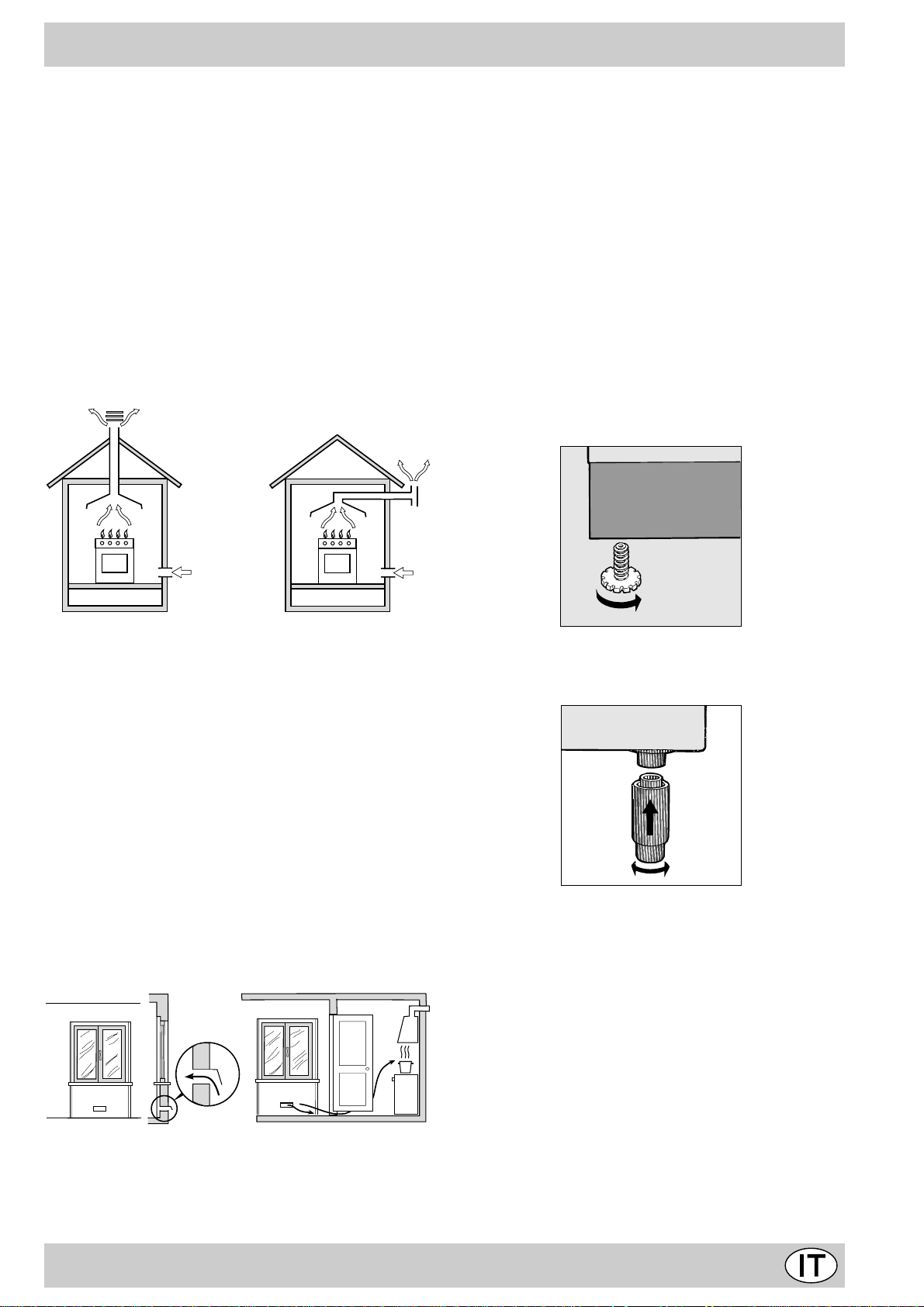
a) Il locale deve pre vedere un sistema di scarico all’esterno
dei fumi della combustione, realizzato tramite una cappa
o tramite un elettroventilatore che entri automaticamente
in funzione ogni volta che si accende l’apparecchio.
aumentando la potenza di spirazione meccanica se essa
esiste.
d) I gas di petrolio liquefatti, più pesanti dell’aria, ristagnano
verso il basso. Quindi i locali contenenti bidoni di GPL
debbono prevedere delle aperture verso l’esterno così
da permettere l’evacuazione dal basso delle eventuali
fughe di gas. P ertanto i bidoni di GPL, siano essi vuoti o
parzialmente pieni, non debbono essere installati o depositati in locali o vani a livello più basso del suolo
(cantinati, ecc.). É opportuno tenere nel locale solo il bidone in utilizzo, collocato in modo da non essere soggetto all’azione diretta di sorgenti di calore (forni, camini,
stufe, ecc.) capaci di portarlo a temperature superiori ai
50°C.
Livellamento (presente solo su alcuni modelli)
Per poter livellare la cucina vengono forniti dei piedini di
regolazione. In caso di necessità questi piedini possono essere avvitati nelle apposite sedi poste negli angoli alla base
della cucina.
In camino o in canna fumaria ramificata Direttamente all’esterno
(riservata agli apparecchi di cottura)
b) Il locale deve prevedere un sistema che consenta l’af-
flusso dell’aria necessaria alla regolare combustione. La
portata di aria necessar ia alla combustione non deve
essere inferiore a 2 m3/h per kW di potenza installata. Il
sistema può essere realizzato prelevando direttamente
l’aria dall’esterno dell’edificio tramite un condotto di almeno 100 cm2 di sezione utile e tale che non possa essere accidentalmente ostruito. Per gli apparecchi privi sul
piano di lavoro , del dispositiv o di sicurezza per assenza
di fiamma, le aperture di ventilazione debbono essere
maggiorate nella misura del 100%, con un minimo di
200cm2 (Fig. A). Ovvero, in maniera indiretta da locali adiacenti, dotati di un condotto di ventilazione con l’esterno
come sopra descritto, e che non siano parti comuni dell’immobile, o ambienti con pericolo di incendio, o camere
da letto (Fig. B).
Particolare A Locale Locale da
adiacente ventilare
A
Esempi di aperture di ventilazione Maggiorazione della fessura fra
per l’aria comburente porta e pavimento
Fig. A Fig. B
c) Un utilizzo intensivo e prolungato dell’apparecchio può
necessitare di una aerazione supplementare per esempio l’apertura di una finestra o una aerazione più efficace
Montaggio gambe (presente solo su alcuni modelli)
V engono fornite delle gambe da montare ad incastro sotto la base della cucina.
Installazione della cucina
La cucina è predisposta con grado di protezione contro i
riscaldamenti eccessivi di tipo X, è pertanto possibile l’installazione a fianco di mobili la cui altezza non superi quella
del piano di lavoro . La parete a contatto con la parete posteriore della cucina deve essere in materiale ininfiammabile.
Durante il funzionamento la parete posteriore della cucina
può raggiungere una temperatura di 50°C superiore a quella ambiente. Per una corretta installazione della cucina v anno osservate le seguenti precauzioni:
a) I mobili situati a fianco, la cui altezza superi quella del
piano di lavoro, debbono essere situati ad almeno 200
mm. dal bordo del piano stesso.
b) Le cappe debbono essere installate secondo i requisiti
richiesti nei libretti istruzioni delle cappe stesse e comunque ad una distanza minima di 650 mm.
c) Allorchè la cucina v enga installata sotto un pensile, que-
st’ultimo dovrà mantenere una distanza minima dal pia-
3
Page 3
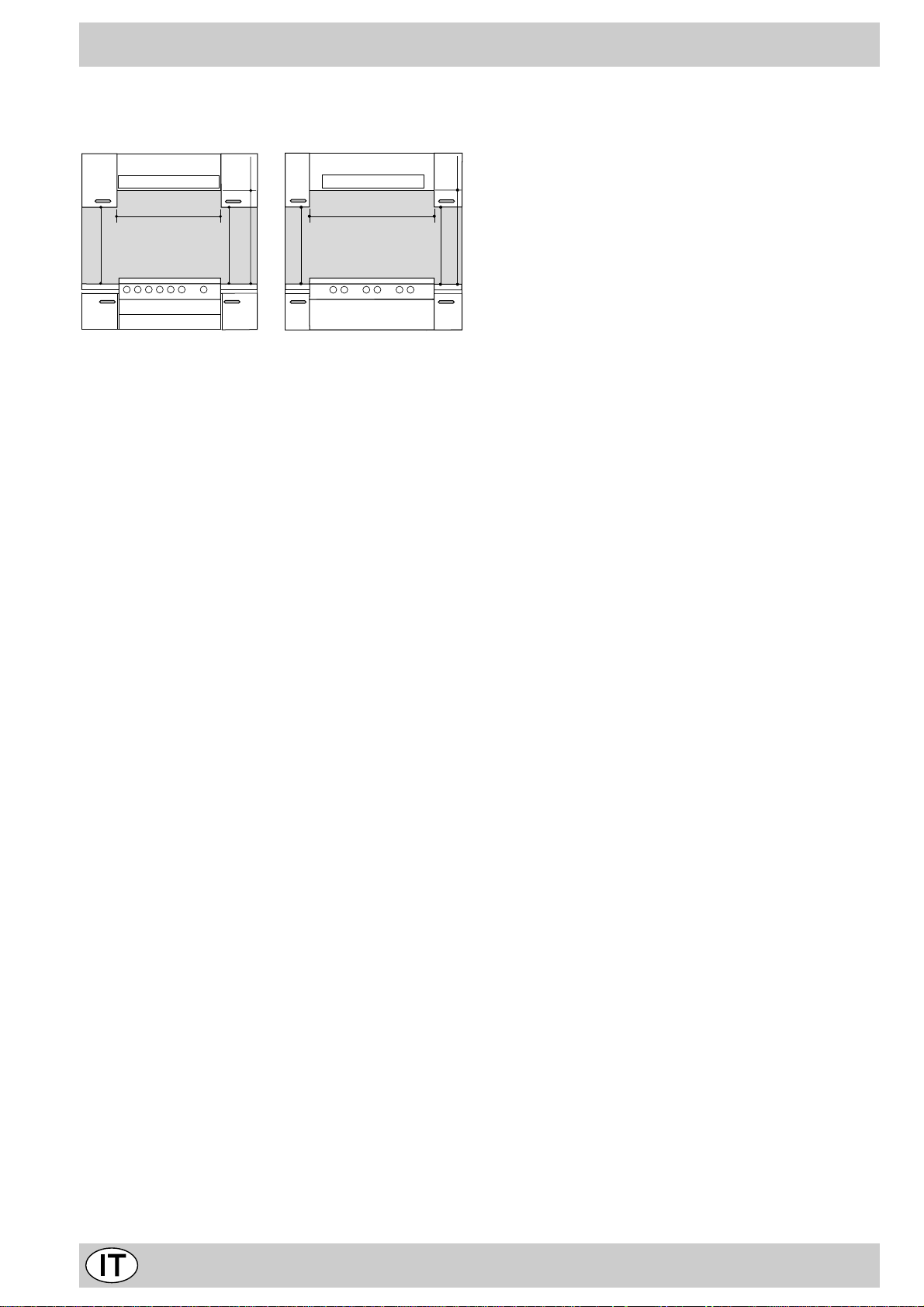
no di 700 mm (millimetri). I mobili adiacenti alla cappa
dovranno mantenere una distanza minima dal piano di
420 mm. come da Fig. C e D.
Allorchè la cucina venga installata secondo le condizioni della
classe 2 sottoclasse 1 è opportuno collegarsi alla rete gas
solamente tramite tubo metallico flessibile conforme alla
UNI-CIG 9891.
HOOD
Min. mm.
900
mm. with hood
420
650
Min. mm.
min.
mm.
420
Min.
HOOD
Min. mm.
600
mm. with hood
420
650
Min. mm.
min.
mm. without hood
700
min.
mm.
420
Min.
Fig. C Fig. D
Collegamento gas
Il collegamento dell’apparecchio alla tubazione o alla bombola del gas dovrà essere effettuato come prescritto dalle
Norme UNI-CIG 7129 e 7131, solo dopo essersi accertati
che esso è regolato per il tipo di gas con cui sarà alimentato.
In caso contrario eseguire le operazioni indicate al paragrafo “Adattamento ai diversi tipi di gas”. Su alcuni modelli l’alimentazione del gas può avvenire indifferentemente da destra o da sinistra a seconda dei casi; per cambiare il collegamento è necessario invertire il portagomma con il tappo di
chiusura e sostituire la guarnizione di tenuta (in dotazione
con l’apparecchio). Nel caso di alimentazione con gas liquido, da bombola, utilizzare regolatori di pressione conformi
alle Norme UNI-CIG 7432.
Importante: per un sicuro funzionamento, per un adeguato
uso dell’energia e maggiore durata dell’apparecchiatura,
assicurarsi che la pressione di alimentazione rispetti i valori
indicati nella tabella 1 “Caratteristiche dei bruciatori ed ugelli”.
Allaccio con tubo flessibile
Eseguire il collegamento per mezzo di un tubo flessibile per
gas rispondente alle caratteristiche indicate nelle norme UNICIG 7140.
Il diametro interno del tubo da utilizzare deve essere:
- 8mm per alimentazione con gas liquido;
- 13mm per alimentazione con gas metano.
In particolare, per la messa in opera di tali tubi flessibili, debbono essere rispettate le seguenti prescrizioni:
• Non deve essere in nessun punto del suo percorso a
contatto con parti che siano a temperature maggiori di
50°C;
• Abbia una lunghezza inferiore a 1500 mm;
• Non sia soggetto ad alcun sforzo di trazione e di torsio-
ne, inoltre non deve presentare curve eccessivamente
strette o strozzature;
• Non venga a contatto con corpi taglienti, spigoli vivi e
con parti mobili o schiacciato;
• Deve essere facilmente ispezionabile lungo tutto il per-
corso allo scopo di poter controllare il suo stato di con-
servazione;
Assicurarsi che il tubo sia ben calzato alle sue due estremità
e fissarlo per mezzo di fascette di serraggio conformi alla
UNI-CIG 7141. Qualor a una o più di queste condizioni non
possa essere rispettata, bisognerà ricorrere ai tubi metallici
flessibili, conformi alla norma UNI-CIG 9891.
Allaccio con tubo flessibile in acciaio inossidabile a
parete continua con attacchi filettati
Eliminare il portagomma già presente sull’apparecchio. Il
raccordo di entrata del gas all’apparecchio è filettato 1/2 gas
mm. without hood
maschio cilindrico. Utilizzare esclusivamente tubi conformi
700
alla Norma UNI-CIG 9891 e guarnizioni di tenuta conformi
min.
alla UNI-CIG 9264. La messa in opera di tali tubi de ve essere effettuata in modo che la loro lunghezza, in condizioni di
massima estensione, non sia maggiore di 2000 mm. Ad allacciamento avvenuto assicurarsi che il tubo metallico flessibile non venga a contatto con parti mobili o schiacciato.
Controllo tenuta
Importante: ad installazione ultimata controllare la perfetta
tenuta di tutti i raccordi utilizzando una soluzione saponosa
e mai una fiamma.
Allacciamento del cavo di alimentazione alla rete
Montare sul cavo una spina normalizzata per il carico indicato sulla targhetta caratteristiche, nel caso di collegamento
diretto alla rete è necessario interporre tra l’apparecchio e la
rete un interruttore omnipolare con apertura minima fra i
contatti di 3 mm. dimensionato al carico e rispondente alle
norme in vigore (il filo di terra non deve essere interrotto
dall’interruttore). Il cavo di alimentazione deve essere posizionato in modo che non raggiunga in nessun punto una
temperatura superiore di 50°C a quella ambiente. Prima di
effettuare l’allacciamento accertarsi che:
• la valvola limitatrice e l’impianto domestico possano sopportare il carico dell’apparecchiatura (vedi targhetta caratteristiche);
• l’impianto di alimentazone sia munito di efficace collegamento a terra secondo le norme e le disposizioni di legge;
• la presa o l’interruttore omnipolare siano facilmente
raggiungibili con il piano installato.
N.B: non utilizzare riduzioni, adattatori o derivatori in quanto
essi potrebbero provocare riscaldamenti o bruciature.
Adattamento del piano ai diversi tipi di gas
Per adattare la cucina ad un tipo di gas div erso da quello per
il quale essa è predisposta (indicato sulla etichetta fissata al
coperchio), occorre effettuare le seguenti operazioni:
a) Sostituire il portagomma già montato con quello conte-
nuto nella confezione “accessori della cucina”.
Attenzione: Il portagomma per gas liquido porta stampigliato
il numero 8, quello per gas metano il numero 13). A vv alersi
comunque di una guarnizione di tenuta nuova.
b) Sostituzione degli ugelli dei bruciatori del piano:
• togliere le griglie e sfilare i bruciatori dalle loro sedi;
• svitare gli ugelli, ser vendosi di una chiave a tubo da 7
mm, e sostituirli con quelli adatti al nuovo tipo di gas (vedi
tabella 1 “Caratteristiche dei bruciatori ed ugelli”).
• rimettere in posizione tutti i componenti seguendo le operazioni inverse rispetto alla sequenza di cui sopra.
4
Page 4
V
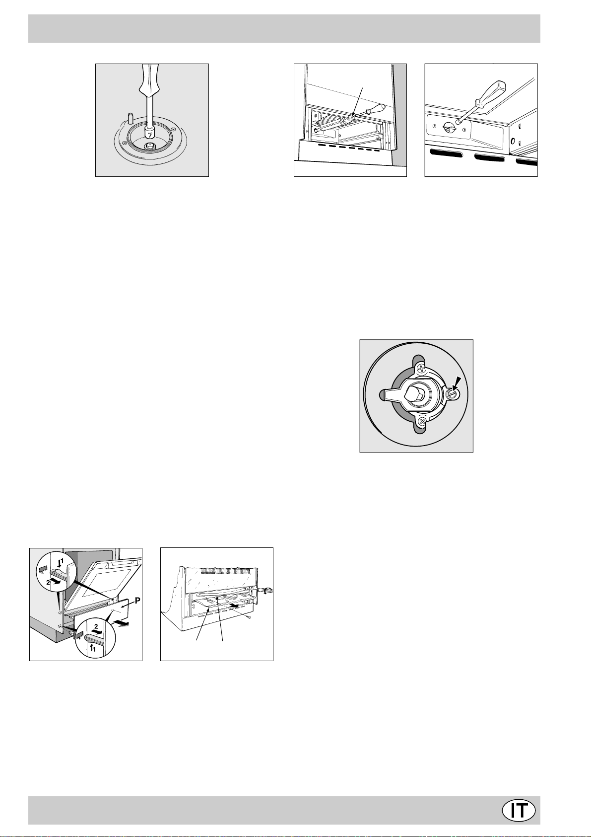
c) Regolazione minimi dei bruciatori del piano:
• portare il rubinetto sulla posizione di minimo;
• togliere la manopola ed agire sulla vite di regolazione
posta all’interno o di fianco all’astina del rubinetto fino ad
ottenere una piccola fiamma regolare.
N.B.: nel caso dei gas liquidi, la vite di regolazione dovrà
essere avvitata a fondo .
• verificare poi che ruotando rapidamente il rubinetto dalla
posizione di massimo a quella di minimo, non si abbiano
spegnimenti del bruciatore.
d) Regolazione aria primaria dei bruciatori del piano:
I bruciatori non necessitano di alcuna regolazione dell’aria
primaria.
Adattamento del forno gas ai diversi tipi di gas
a) Sostituzione dell’ugello del bruciatore del forno:
• togliere il cassetto scaldavivande;
• nei modelli senza cassetto togliere il pannello “P” come
indicato in Fig. E. Dopo a ver aperto la porta, sganciare i
due inserti superiori premendoli verso il basso , poi i due
inferiori premendoli verso l’alto;
• sfilare la protezione scorrevole “A”;
• togliere le due viti che consentono lo smontaggio della
protezione “B”; (v edi Fig. F);
• rimuovere il bruciatore del forno dopo aver tolto la vite “V”
(vedi Fig. G); L’ operazione viene facilitata togliendo la
porta del forno.
• svitare l’ugello del bruciatore forno servendosi dell’apposita chiave a tubo per ugelli (vedi Fig. H), o meglio ancora
di una chiave a tubo di 7 mm e sostituirlo con quello adatto
al nuovo tipo di gas (v edi tabella 1).
Fig. G Fig. H
b) Regolazione del minimo del bruciatore forno gas
termostatato:
• accendere il bruciatore come descr itto al paragrafo “la
manopola del forno” del libretto d’uso;
• por tare la manopola sulla posizione di Min dopo aver
lasciato la stessa per 10 minuti circa in posizione Max;
• togliere la manopola;
• agire sulla vite di regolazione posta all’esterno
dell’astina del termostato fino ad ottenere una piccola
fiamma regolare (vedi figura sotto);
N.B.: nel caso dei gas liquidi, la vite di regolazione
dovrà essere avvitata a fondo.
• verificare poi che ruotando rapidamente la manopola dalla
posizione Max alla posizione di Min o con rapide aperture e chiusure della porta del forno non si abbiano
spegnimenti del bruciatore.
Regolazione aria primaria del bruciatore forno
Il bruciatore forno non necessita di alcuna regolazione dell’aria primaria.
B
A
Fig. E Fig. F
Attenzione
Al termine dell’operazione sostituire la vecchia etichetta di
taratura con quella corrispondente al nuovo gas di utilizzo,
reperibile presso i nostri Centri Assistenza Tecnica.
Nota
Qualora la pressione del gas utilizzato sia diversa (o v ariabile) da quella prevista, è necessario installare, sulla tubazione d’ingresso un appropriato regolatore di pressione (secondo UNI-CIG 7430 “regolatori per gas canalizzati”).
5
Page 5
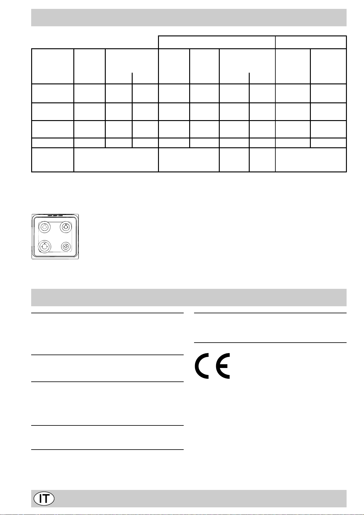
Caratteristiche dei bruciatori ed ugelli
Tabella 1 Gas liquido Gas naturale
Bruciat or e Diametro
(mm)
Rapido
(Grande) (R)
Semi Rapido
(Medio) (S)
Ausiliario
(Piccolo) (A)
Forno - 3,02 1,0 49 85 219 216 132 288
Pressioni d i
alimentazione
100 3,00 0,7 41 86 218 214 116 286
75 1,90 0,4 30 70 138 136 106 181
55 1,00 0,4 30 50 73 71 79 95
Potenza termica
kW (p.c.s.*)
Nomin. Ridot . (mm) (mm) *** ** (mm)
Nominale (mbar )
Minima (mbar)
Massi ma ( mb ar )
By-pass
1/100
Ugello
1/100
Port at a *
28-30 ***
20 ***
35 ***
g/h
37 **
25 **
45 **
Ugell o
1/100
Port at a *
20
17
25
* A 15°C e 1013 mbar-gaz secco
** Propano P.C.S . = 50,37 MJ/Kg
*** Butano P.C.S . = 49,47 MJ/Kg
Naturale P.C.S . = 37,78 MJ/m
S
S
R
A
3
l/h
C 642 G...
C 647 G...
Caratteristiche tecniche
Dimensioni utili del forno:
larghezza cm. 40,7
profondità cm. 40
altezza cm. 34
V olume utile del forno:
Dimensioni utili del cassetto scaldavivande:
larghezza cm. 43
profondità cm. 43
altezza cm. 8
T ensioni e frequenza di alimentazione:
vedi targhetta caratteristiche
Bruciatori:
adattabili a tutti i tipi di gas indicati nella terghetta
caratteristiche
litri 55
Questa apparecchiatura è conforme alle seguenti
Direttive Comunitarie:
- 73/23/CEE del 19/02/73 (Bassa Tensione) e successive modificazioni;
- 89/336/CEE del 03/05/89 (Compatibilità Elettromagnetica) e successive modificazioni;
- 90/396/CEE del 29/06/90 (Gas) e successive
modificazioni;
- 93/68/CEE del 22/07/93 e successive modificazioni.
6
Page 6
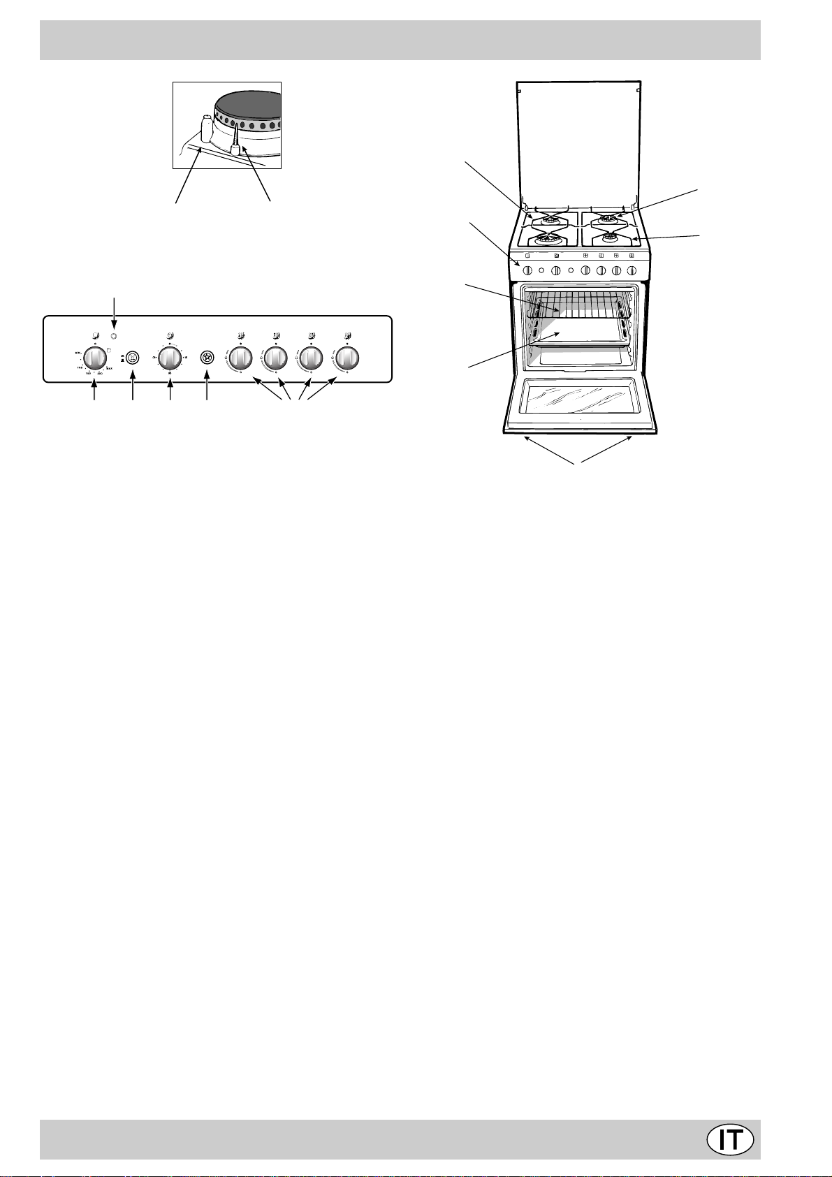
La cucina con forno gas e grill elettrico
A
C
D
Q
1
0
MOPL N
A Piano di contenimento eventuali trabocchi
C Bruciatore a gas
D Dispositivo di accensione istantanea elettronica
E Griglia del piano di lavoro
F Cruscotto
G Piedini o gambe regolabili
H Leccarda o piatto di cottura
K Dispositivo di sicurezza
I Griglia ripiano del forno
K
F
E
I
H
G
L Accensione elettronica dei bruciatori del piano (pre-
sente solo su alcuni modelli)
M Manopola del f orno e grill
N Manopole di comando bruciatori gas del piano di cot-
tura
O Pulsante luce forno e girarrosto (presente solo su al-
cuni modelli)
P Manopola del contaminuti
Q La spia di funzionamento del grill
7
Page 7
Le diverse funzioni presenti nella cucina
F
La selezione delle varie funzioni presenti nella cucina avviene agendo sui dispositivi ed organi di comando posti sul
cruscotto della stessa.
Le manopole di comando dei bruciatori a gas del
piano di cottura
In corrispondenza di ciascuna delle manopole è indicata,
con un cerchietto pieno •, la posizione del bruciatore a gas
da essa comandato. P er accendere uno dei bruciatori, avvicinare allo stesso una fiamma o un accenditore.
Premere a fondo e ruotare la manopola corrispondente in
senso antiorario fino alla posizione di massimo .Ciascun
bruciatore può funzionare al massimo della sua potenza, al
minimo, o con potenze intermedie. In relazione a queste diverse prestazioni, sulla manopola, oltre alla posizione di spen-
to, individuata dal simbolo • quando questo à posto in corri-
spondenza della tacca di riferimento, sono indicate le posizioni di massimo e di minimo .
Esse si ottengono facendo ruotare la manopola in senso
antiorario dalla posizione di spento.P er spegnere il bruciatore occorre invece ruotare la manopola in senso orario fino
all’arresto (corrispondente di nuovo al simbolo • ).
volta si avv erte durante questa operazione è dovuto all’evaporazione delle sostanze usate per proteggere il forno durante l’intervallo di tempo che intercorre tra la produzione e
l’installazione del prodotto.
Attenzione: Utilizzare il primo ripiano dal basso solamente
nel caso di cotture con girarrosto (ove presente). Per le
altre cotture non utilizzate mai il primo ripiano dal basso e
non appoggiate mai oggetti sul fondo del forno mentre
state cuocendo perchè potreste causare danni allo smalto. Ponete sempre i Vostri recipienti di cottura (pirofile,
pellicole di alluminio, ecc. ecc.) sulla griglia in dotazione
con l’apparecchio appositamente inserita nelle guide del
forno.
La manopola del forno e del grill (M)
E’ il dispositivo che permette di selezionare le diverse funzioni del forno e di scegliere la temperatura di cottura più
idonea ai cibi da cuocere fra quelle indicate sulla manopola
stessa (comprese fra Min e Max).
Per accendere il bruciatore forno , a vvicinare al f oro “F ” una
fiamma o un accenditore, contemporaneamente premere a
fondo e ruotare la manopola forno in senso antiorario fino
alla posizione Max.
Accensione elettronica dei bruciatori del piano
(presente solo su alcuni modelli)
Alcuni modelli sono dotati di accensione istantanea elettronica dei bruciatori a gas del piano di cottura: essi sono riconoscibili per la presenza del dispositivo di accensione (vedi
dettaglio D). Questo dispositiv o entra in funzione esercitando una leggera pressione sul pulsante “L” identificato dal sim-
bolo . P er accendere il bruciatore prescelto è perciò sufficiente premere il pulsante “L” e contemporaneamente premere a fondo e ruotare in senso antiorario la manopola corrispondente fino all’avvenuta accensione. Per un’accensio-
ne immediata è consigliabile prima premere il pulsante
poi ruotare la manopola. Alcuni modelli sono dotati di ac-
censione elettronica integrata all’interno della manopola, in
questo caso è presente il dispositivo di accensione “D” ma
non il pulsante “L”. Per accendere il bruciatore prescelto è
sufficiente premere a fondo la manopola corrispondente e
ruotarla in senso antiorario fino alla posizione di massimo
tenendola premuta fino alla avvenuta accensione. Av-
vertenza: nel caso di una estinzione accidentale delle
fiamme del bruciatore, chiudere la manopola di comando e non ritentare l’accensione se non dopo almeno 1
minuto.
Modelli con dispositivo di sicurezza contr o fughe di
gas per i bruciatori del piano
Potete identificare questi modelli per la presenza del dispositivo (V edi dettaglio K).
Importante: dato che i bruciatori del piano sono dotati di
dispositivo di sicurezza, dopo l’accensione del bruciatore, è
necessario mantenere premuta la manopola per circa 6
secondi in modo da consentire il passaggio del gas finché
non si scalda la termocoppia di sicurezza.
Attenzione: prima di utilizzare il forno per la prima volta,
accendetelo, con il termostato al massimo, per circa mezz’ora con la porta aperta ed aerare il locale. L’odore che tal-
Dato che la cucina è dotata di dispositivo di sicurezza è
necessario mantenere premuta la manopola per circa 6
secondi in modo da consentire il passaggio del gas. (P er
i modelli dotati di accensione elettronica vedi il relativo
paragrafo).
La selezione della temperatura di cottura si ottiene facendo
corrispondere l’indicazione del valore desiderato con il riferimento posto sul cruscotto; la gamma completa delle temperature ottenibili è riportata qui sotto.
Min • 150 • 180 • 220 Max
130 140 160 200 250
La temperatura impostata viene automaticamente raggiunta e mantenuta costante dall’organo di controllo (il termostato) comandato dalla manopola.
Premendo a fondo e ruotando la manopola “M” fino alla po-
sizione si mette in funzione il grill a raggi infrarossi, che
permette la doratura dei cibi oltre ad essere consigliato per
la cottura di arrosti (braciole, salsicce, roast-beef).
Avvertenza importante: nel caso di una estinzione accidentale delle fiamme dei bruciatori del forno, chiudere la
manopola di comando del bruciatore e non riaccendere il
bruciatore prima di un minuto.
8
Page 8

Accensione elettronica del bruciatore del forno
(presente solo su alcuni modelli)
Per accendere il bruciatore forno premere il pulsante iden-
tificato col simbolo , contemporaneamente premere a
fondo e ruotare la manopola forno (M) in senso antiorario
fino alla posizione Max.
Ad accensione avvenuta rilasciare il tasto preposto all’accensione mantenendo però premuta la manopola per
circa 6 secondi in modo da consentire il passaggio del
gas.
Nel caso di mancanza di elettricità potete accendere manualmente il forno seguendo le istruzioni riportate nel paragrafo “La manopola del f orno e del grill”. Il dispositiv o di accensione elettronica dei bruciatore del forno, non deve essere azionato per più di 15 secondi. Se in seguito a questi
15 secondi il bruciatore non si è acceso, cessare di agire sul
dispositivo , aprire la porta del forno ed attendere almeno un
minuto prima di un nuovo tentativo d’accensione del bruciatore.
Il girarrosto
Alcuni modelli, pur non avendo il girarrosto di serie, danno la
possibilità di installarlo successivamente, richiedendo il kit
(Cod. 051671) presso un rivenditore autorizzato o presso il
Servizio Assistenza Tecnica Merloni Elettrodomestici.
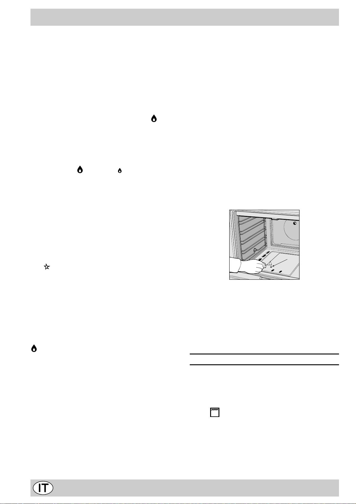
Per azionare il girarrosto procedere nel modo seguente:
a) posizionare sulla leccarda il sostegno del girarrosto ed
appoggiare su di esso lo spiedo (vedi Fig. I);
b) inserire la leccarda nel 2° ripiano dal basso spingendo a
fondo fino all’avv enuto inserimento della parte terminale
dello spiedo nel foro posto sul fondo del f orno.
Nota: alcuni modelli sono dotati di un sostegno del girarrosto di tipo diverso (vedi Fig. L), in tal caso le due operazioni
descritte vanno così modificate:
a1)inserire il gancio di sostegno nei due fori posti nella parte
inferiore della protezione grill (posizione 1);
b1)inserire lo spiedo nel foro posto al centro della parte po-
steriore del forno avendo cura che l’anello di appoggio
anteriore dello spiedo sia posizionato correttamente sul
gancio di sostegno (posizione 2);
c) azionare il gir arrosto premendo il pulsante "O".
1
1
2
La spia di funzionamento del grill (Q)
Risulta accesa quando sia stato messo in funzione un
qualsivoglia elemento elettrico riscaldante del forno.
Il pulsante per l’accensione della luce del forno (O)
E’ quello individuato dal simbolo e consente con l’accensione della lampada all’interno del forno, di seguire l’anda-
mento della cottura senza aprire la porta.
La manopola del contaminuti (P)
Per utilizzare il contaminuti occorre caricare la suoneria
ruotando la manopola di un giro quasi completo in senso
orario; quindi, tornando indietro, impostare il tempo desiderato facendo coincidere con il riferimento fisso del frontalino
il numero corrispondente ai minuti prefissati.
Attenzione
Durante la cottura la porta del forno è calda, impedite che i
bambini vi si avvicinino.
Consigli pratici per l’uso dei bruciatori
Al fine di ottenere il massimo rendimento è utile ricordare
quanto segue:
• utilizzare recipienti adeguati a ciascun bruciatore (vedere tabella) alfine di evitare che le fiamme fuoriescano dal
fondo dei recipienti.
• utilizzare solamente recipienti a fondo piatto.
• al momento dell’ebollizione ruotare la manopola fino alla
posizione di minimo.
• utilizzare sempre recipienti con coperchio.
Brucia tore ø Diametro recipie nti (cm)
Rapido (R) 24 – 26
Semi Rapido (S) 16 – 20
Ausiliario (A) 10 – 14
N.B. Sui modelli dotati di griglietta di riduzione, quest’ultima
dovrà essere utilizzata solo per il bruciatore ausiliario, quando si utilizzano dei recipienti di diametro inferiore a 12 cm.
3° Vetr o
Al fine di ottenere una temperatura più bassa della porta
forno durante il funzionamento, ed un minor consumo di energia, è disponibile un kit supplementare di protezione. Questo kit dovrebbe essere montato in caso di presenza di bambini piccoli. P er f are questo è necessario acquistare il kit codice ricambio 053413 presso un rivenditore autorizzato o
presso il Servizio Assistenza T ecnica riportato sulla lista fornita a corredo.
Fig. I Fig. L
9
Page 9

Consigli pratici per la cottura
Il forno mette a vostra disposizione una vasta gamma di
possibilità che consentono di cuocere ogni cibo nella
maniera migliore. Con il tempo potrete sfruttare al meglio
questo versatile apparecchio di cottura, pertanto le note
riportate di seguito sono solamente delle indicazioni di
massima che potrete ampliare con la vostra esperienza
personale.
Cottura dei dolci
Nella cottura dei dolci infornate sempre a forno caldo, attendete la fine di preriscaldamento, circa 15 minuti.
Le temperature sono normalmente nell’intorno di 160°C.
Non aprite la porta durante la cottura, per evitare un abbassamento del dolce. Gli impasti sbattuti non dev ono essere troppo fluidi, per non prolungare troppo i tempi di
cottura.
In generale:
Dolce troppo secco
La prossima volta impostate una temperatura di10°C
superiore e ri ducete il tempo di cot tura.
Dolce si abbassa
Usate meno liquido o abbassate la temperatura di 10°C.
Cottura del pesce e della carne
La carne deve pesare almeno 1 Kg. per evitare che si
asciughi troppo. Per le carni bianche, i volatili ed il pesce
utilizzate temperature basse (150°C-175°C).Per le carni
rosse che si vuole siano ben cotte all’esterno conservando all’interno il sugo, è bene iniziare con una temperatura
iniziale alta (200-220°C) per breve tempo, per poi diminuirla successivamente. In generale, più grosso è l’arrosto, più bassa dovrà essere la temperatura e più lungo il
tempo di cottura. Ponete la carne da cuocere al centro
della griglia ed inserite sotto la griglia la leccarda per raccogliere i grassi. Inserite la griglia in modo che il cibo si
trovi al centro del forno. Se v olete più calore da sotto , utilizzate i ripiani più bassi. Per ottenere arrosti saporiti
bardate la carne con lardo o pancetta e posizionatela in
modo che sia nella parte superiore.
Utilizzo del grill
Importante: effettuare la cottura al grill con porta del
forno chiusa, ciò per ottenere unitamente ai migliori ri-
sultati un sensibile risparmio di energia (10% circa).
Nell’utilizzo delle funzioni grill disponete la griglia sugli
ultimi ripiani partendo dal basso (vedi tabella cottura)
dopodiché, per raccogliere i grassi ed evitare la f ormazione di fumo, disponete una leccarda nel primo ripiano dal
basso.
Dolce scuro superi orment e
Inseritelo ad al tezza inferior e, impostate una
temperatura più bassa e prolungate la cottura.
Buona cott ur a e ster na, ma i nter no col loso
Usate meno liquido, riducete la temperatura, aumentate
il tempo di cottura.
Dol ce non si stacca dallo st ampo
Ungete bene lo stampo e cospargetelo anche con un
pò di farina.
Ho cot to su pi ù ripia ni e non tutti sono allo stesso
a vanz ame nto di cott ur a
Impostate una temperatura inferiore.
Non necessariamente ripi ani inseriti
contemporaneamente debbono essere tolti insieme.
10
Page 10

Consigli pratici per la cottura al forno
Cibo da cucinare Peso
(Kg)
Pasta
Lasagne 2,5 3 210 - 75-80
Cannelloni 2,5 3 210 - 75-80
Tagliatelle 2,5 3 210 - 75-80
Carni
Vitello 1,7 3 230 - 85-90
Pollo 1,5 3 220 - 110-115
Tacchino 3,0 3 MAX - 95-100
Anatra 1,8 3 230 - 120- 125
Coniglio 2 3 230 - 105-110
Maiale 2,1 3 230 - 100-110
Agnello 1,8 3 230 - 90-95
Pesci
Sgombri 1,1 3 210-230 - 55-60
Dentice 1,5 3 210-230 - 60-65
Trota al cartocci o 1,0 3 210-230 - 40-45
Pizza
Napoletana 1,0 3 MAX 15 30-35
Torte
Biscotti 0,5 3 180 15 30-35
Crostata 1,1 3 180 15 30-35
Torta al cioccola to 1 3 200 15 45- 50
Torta lievitata 1 3 200 15 50-55
Cottura al grill
Toast n.° 4 4 10
Braciole di maiale 1,5 4 30
Sgombri 1,1 4 35
Cottura al girar rosto
Vitello allo spiedo 1 2 80
Pollo allo spiedo 2 2 90
Nota: i tempi di cott ura sono puramente indicat ivi e poss ono variare in bas e ai gust i personal i.
Posizione cottura
ripiani dal basso
Temperatura
(°C)
Tempo d i
preriscaldamento
(minuti)
Tempo d i
cottura
(minuti)
11
Page 11

Manutenzione ordinaria e pulizia della cucina
Prima di ogni operazione disinserire elettricamente la
cucina. Per una lunga dur ata della cucina è indispensabi-
le eseguire frequentemente una accurata pulizia generale, tenendo presente che:
• le par ti smaltate e i pannelli autopulenti, se presenti,
vanno lavate con acqua tiepida senza usare polveri
abrasive e sostanze corrosiv e che potrebbero rovinarle;
• l’interno del forno va pulito, con una certa frequenza,
quando è ancora tiepido usando acqua calda e detersivo, risciacquando ed asciugando poi accuratamente;
• gli spartifiamma vanno lav ati frequentemente con acqua calda e detersivo avendo cura di eliminare le
incrostazioni. Nelle cucine dotate di accensione automatica occorre procedere frequentemente ad una accurata pulizia della parte terminale dei dispositivi di
accensione istantanea elettronica (vedi riquadro dell’ultima pagina di copertina) e verificare che i fori di
uscita del gas degli spartifiamma non siano ostruiti;
• l’acciaio inox può rimanere macchiato se rimane a contatto per lungo tempo con acqua fortemente calcarea
o con detergenti aggressivi (contenenti fosforo). Si consiglia di sciacquare abbondantemente ed asciugare
dopo la pulizia. E’ inoltre oppor tuno asciugare eventuali trabocchi d’acqua;
• nei modelli dotati di coperchio in cristallo la pulizia si
effettua con acqua calda evitando l’impiego di panni
ruvidi o sostanze abrasive.
N.B.: evitare di chiudere il coper chio fino a che i bruciatori gas sono ancora caldi.
Importante: controllare periodicamente lo stato di con-
servazione del tubo flessibile di collegamento gas e sostituirlo non appena presenta qualche anomalia; è
consigliabile la sostituzione annuale.
Sostituzione della lampada nel vano forno
• T ogliere l’alimentazione alla cucina tramite l’interruttore omnipolare utilizzato per il collegamento della cucina all’impianto elettrico, o scollegare la spina, se accessibile;
• Svitare il coperchio in vetro del portalampada;
• Svitare la lampada e sostituirla con una resistente ad
alta temperatura (300°C) con queste caratteristiche:
- T ensione 230V
- Potenza 25W
- Attacco E14
• Rimontare il coperchio in vetro e ridate alimentazione
al forno.
Ingrassaggio dei rubinetti
Con il tempo può verificarsi il caso di un rubinetto che si
blocchi o presenti difficoltà nella rotazione, pertanto sarà
necessario provvedere alla pulizia interna e alla sostituzione del grasso.
N.B.: Questa operazione deve essere eff ettuata da
un tecnico autorizzato dal costruttore.
12
Page 12

Important
T o maintain the EFFICIENCY and SAFETY of this appliance, we recommend:
• call only the Service Centers authorized by the manufacturer
• always use original Spare Parts
1
This appliance is intended for nonprofessional use
within the home.
2 These instructions are only for those countries whose
symbols appear in the booklet and on the serial no.
plate of the appliance.
3 This owner’s manual is for a c lass 1 appliance (in-
sulated) or class 2, subc lass 1 appliances (installed
between two cabinets.
4 Before using your appliance, read the instructions in
this owner’s manual carefully since it provides all the
information you need to ensure safe installation, use
and maintenance. Always keep this owner’s manual
close to hand since you may need to refer to it in the
future.
5 When you have removed the packing, check that the
appliance is not damaged. If y ou ha v e an y doubts , do
not use the appliance and contact your nearest Ariston
Service Centre. Ne v er lea v e the pac king components
(plastic bags, polystyrene foam, nails , etc.) within the
reach of children since they are a source of potential
danger.
6 The appliance must be installed only by a qualified tech-
nician in compliance with the instructions provided. The
manufacturer declines all liability f or improper installation, which may result in personal injury and damage
to property.
7 The electrical safety of this appliance can only be guar-
anteed if it is correctly and efficiently earthed, in compliance with regulations on electrical safety. Always
ensure that the earthing is efficient. If you have any
doubts, contact a qualified technician to check the system. The manuf acturer declines all liability for damage
resulting from a system which has not been earthed.
8 Before plugging the appliance into the mains, check
that the specifications indicated on the date plate (on
the appliance and/or packaging) correspond with those
of the electrical and gas systems in your home.
9 Check that the electrical capacity of the system and
sockets will support the maximum power of the appliance, as indicated on the data plate. If you have any
doubts, contact a qualified technician.
10 An omnipolar switch with a contact opening of at least
3 mm or more is required for installation.
11 If the socket and appliance plug are not compatible,
have the socket replaced with a suitable model by a
qualified technician, who should also check that the
cross-section of the socket cable is sufficient for the
power absorbed by the appliance. The use of adaptors, multiple sockets and/or e xtensions, is not recommended. If their use cannot be avoided, remember to
use only single or multiple adapters and extensions
which comply with current safety regulations. In these
cases, never exceed the maximum current capacity
indicated on the individual adaptor or extension and
the maximum power indicated on the multiple adapter .
12 Do not leave the appliance plugged in if it is not in use.
Switch off the main switch and gas supply when you
are not using the appliance.
13 The openings and slots used for ventilation and heat
dispersion must nev er be cov ered.
14 The user must not replace the supply cable of this ap-
pliance. Always contact an after-sales service centre
which has been authorised by the manufacturer if the
cable has been damaged or needs replacement.
15 This appliance must be used for the purpose for which
it was expressly designed. Any other use (e .g. heating
rooms) is considered to be improper and consequently
dangerous. The manufacturer declines all liability for
damage resulting from improper and irresponsible use.
16 A number of fundamental rules must be followed when
using electrical appliances. The following are of particular importance:
• Do not touch the appliance when your hands or feet
are wet.
• Do not use the appliance barefooted.
• Do not use extensions, but if they are necessary,
caution must be exercised.
• Never pull the power supply cab le or the appliance
to unplug the appliance plug from the mains.
• Never leave the appliance e xposed to atmospheric
agents (rain, sun etc.)
• Do not allow children or persons who are not familiar with the appliance to use it, without supervision.
17 Always unplug the appliance from the mains or s witch
off the main switch before cleaning or carrying out maintenance.
18 If you are no longer using an appliance of this type,
remember to make it unserviceable by unplugging the
appliance from the mains and cutting the supply cable.
Also make all potentially dangerous parts of the appliance safe, above all for children who could play with
the appliance.
19 To av oid accidental spillage do not use cookware with
uneven or def ormed bottoms on the burners or on the
electric plates. Tur n the handles of pots and pans inwards to avoid knoc king them o v er accidentally.
20 Some parts of the appliance, in particular the hot plates,
remain heated for a long time after use. Make sure not
to touch them.
21 Never use flammab le liquids such as alcohol or gaso-
line, etc. near the appliance when it is in use.
22 When using small electric appliances near the hob,
keep the supply cord away from the hot parts.
23 Make sure the knobs are in the “•”/”¡” position when
the appliance is not in use.
24 When the grill or the oven are in use, the accessi-
ble parts can become extremely hot. It is recommended that you keep children at a distance.
25 Gas appliances require regular air exchange to en-
sure trouble-free performance. When installing the
cooker, follow the instructions pr ovided in the paragraph on “Positioning” the appliance.
26 The glass top (only on certain models) can shatter if it
is overheated. Therefore, all of the b urners or hot plates
must be turned off before the top is closed.
13
Page 13

Installation
The following instructions should be read by a qualified
technician to ensure that the appliance is installed, regulated and serviced correctly in compliance with current
standards.
Important: Remember to unplug the appliance from
the mains before making adjustments or doing maintenance.
Positioning
Important: This unit may be installed and used only in
permanently ventilated rooms in compliance with current
National Regulations. The following requirements must
be observed:
a) The room must be equipped with an exhaust system
that vents the combustion fumes to the outside. It ma y
consist of a hood or an electric fan that automatically
starts each time the appliance is turned on.
present).
d) Liquified petroleum gas is heavier than the air and,
therefore, settles downw ards. Thus, rooms containing
LPG cylinders must also be equipped with apertures
to the outside for ventilation of gas in the case of leaks.
LPG cylinders must not, therefore, be installed or stored
in rooms or storage areas that are below ground lev el
(cellars, etc.) whether they are partially or completely
full. It is a good idea to keep only the cylinder being
used in the room, positioned so that it is not subject to
heat produced by external sources (ovens, fireplaces,
stoves, etc. ) which are able to increase the temperature of the cylinder above 50°C.
Levelling Y our Appliance (only on certain models)
Your unit is supplied with feet for lev elling the appliance. If
necessary, these feet can be screwed into the housings
in the corners of the cooker base.
Flue or Branched Flue System Directly to the Outside
(only for cooking appliances)
b) The room must also have a system to permit proper
air circulation, needed for combustion to occur normally. The flow of air needed f or combustion m ust not
be less than 2 m3/h per kW of installed power . The air
circulation system may take air directly from the outside by means of a pipe with an inner cross section of
at least 100 cm2; the opening must not be able to be
accidentally blocked. For those appliances not
equipped with a safety de vice for accidental flame loss,
the ventilation apertures must be increased by 100%,
with the minimum being 200cm2 (Fig. A). The system
can also provide the air needed for combustion by indirect means, i.e. from adjacent rooms fitted with air
circulation tubes as described above. Howev er, these
rooms must not be common rooms or bedrooms.
(Fig. B)
Examples of Ventilation Openings Increased Opening Between
.
Detail A Adjacent Room to
Room be V entilated
A
Comburent Air Door and Floor
Fig. A Fig. B
c) Intensive and prolonged use of the appliance may re-
sult in the need for supplemental air circulation, e.g.
opening windows or increasing mechanical venting (if
Mounting the Legs (only on certain models)
The cooker comes with legs that can be mounted beneath
the base of the cooker itself.
Installing the Cooker
The cooker is manufactured with type X degree protection against overheating. Therefore, the appliance can be
installed next to cabinets, provided the y are not taller than
the hob. If the cooker is placed in contact with walls or the
sides of adjacent cabinets, they must be capable of withstanding a rise in temperature of 50°C above room temperature. F or proper installation of the cook er , the following precautions must be taken:
a) Kitchen cabinets installed next to the cooker that are
higher than the top of the hob, must be at least 200
mm from the edge of the hob itself.
b) Hoods must be installed according to the requirements
in the installation manual for the hood and, in any case ,
at a minimum height of 650 mm.
c) If the hood is installed below a wall cabinet, the latter
must be at least 700 mm (millimetres) above the surface of the hob. Cabinets installed adjacent to the hood
must be at least 420 mm above the hob, as shown in
Figures C and D.
14
Page 14

HOOD
Min. mm.
900
mm. with hood
420
650
Min. mm.
min.
mm.
420
Min.
HOOD
Min. mm.
600
mm. with hood
420
650
Min. mm.
min.
mm. without hood
700
min.
mm.
420
Min.
Fig. C Fig. D
Making the Gas Connection
T
he appliance should be connected to the mains or to a
gas cylinder in compliance with current directives. Bef ore
making the connection, check that the cooker is regulated
for the gas supply you are using. If not, follow the instructions indicated in the paragraph “Converting to Different
Types of Gas." On some models the gas supply can be
connected on the left or on the right, as necessary; to
change the connection, reverse the position of the hose
holder with that of the cap and replace the gasket (supplied with the appliance). When using liquid gas from a
cylinder, install a pressure regulator which complies with
the National Regulations.
Important: Check that the supply pressure complies with
the values indicated in table 1 “Burner and Nozzle Characteristics” since this will ensure safe operation, correct
consumption and ensure a longer life for y our appliance.
Connection with a Hose
Make the connection using a gas hose that complies with
requirements set forth by the current standards. The inner diameters of the pipe are as follows:
- 8 mm for liquid gas;
- 13 mm for methane.
When installing the hose, remember to take the following
precautions:
• No part of the hose must come into contact with parts
whose temperature exceeds 50°C;
• The length of the hose should be less than 1500 mm;
• The hose should not be subject to twisting or pulling,
and should not have bends or kinks;
• The hose should not touch objects with sharp edges,
corners or moving parts, and it should not be crushed;
• The full length of the hose should be easy to inspect in
order to check its condition.
Check that the hose fits firmly into place at the two ends
and fix it with clamps complying with current standards. If
any of the above recommendations can not be followed,
flexible metal pipes should be used. If the cooker is installed in compliance with the requirements for class 2,
subclass 1, it is highly recommended that the gas connection be made with a flexible metal pipe in compliance
with current safety standards.
nection has been made, make sure that the flexib le metal
pipe does not come into contact with moveab le parts and
that it is not crushed.
Checking the Seal
Important: Once the installation has been completed,
mm. without hood
check to make sure that the seals on all the connections
700
are tight, using a soapy solution (ne v er a flame).
min.
Connecting the Power Suppl y Cor d to the Mains
Install a normalised plug corresponding to the load indicated on the data plate. When connecting the cable directly to the mains, install an omnipolar circuit-breaker with
a minimum contact opening of 3 mm between the appliance and the mains. The omnipolar circuit break er should
be sized according to the load and should comply with
current regulations (the earth wire should not be interrupted by the circuit breaker). The supply cable should be
positioned so that it does not reach a temperature of more
than 50°C with respect to the room temperature, along its
length. Bef ore making the connection, chec k that:
• The limiter valve and the home system can support
the appliance load (see data plate);
• The mains are properly earthed in compliance with current safety standards and regulations;
• There is easy access to the socket and omnipolar circuit breaker , once the hob has been installed.
N.B.: Never use reducers, adaptors or shunts since the y
can cause heating or burning.
Converting the Cooker to Different Types of Gas
In order to convert the cooker for use with a type of gas
different than the one for which it was factory set (indicated on the label attached to the lid), the following steps
must be taken:
a) Replace the hose holder mounted on the appliance
with that supplied in the bag of “cooker accessories.”
Important: The hose holder for liquid gas is marked 8,
the hose holder for methane. In any case, always use a
new sealing gasket.
b) Replace the burner nozzles on the hob:
• Remove the grids and slide the burners from their
housings;
• Unscrew the nozzles using a 7 mm socket spanner,
and replace them with nozzles for the new type of gas
(see table 1 “Burner and Nozzle Characteristics”).
• Replace all the components by repeating the steps in
reverse order .
Connecting a Flexible, Jointless, Stainless Steel
Pipe to a Threaded Attachment
Remove the hose holder fitted on the appliance. The gas
supply pipe fitting is a threaded 1/2 gas cylindrical male
attachment. Use only pipes and seals that comply with
current National Regulations. The full length of the pipe
when installed must not exceed 2000 mm. After the con-
c) Minimum regulation of the hob burners:
•
Turn the tap to minimum;
• Remove the knob and adjust the regulation scre w, which
is positioned in or next to the tap pin, until the flame is
small but steady.
15
Page 15

N.B.: In the case of liquid gas, the regulation screw
must be screwed in all the wa y.
• Check that the flame does not go out when you turn the
tap quickly from high to low .
d) Regulating the primary air of the burners: The primary air
of the burners does not need to be regulated.
Converting the Oven for Use with Different Types of
Gas
a) Replacing the oven burner nozzle:
• Remove the warming drawer;
• If the appliance comes without warming drawer , remo ve
the “P” panel as indicated in Fig. E. Open the door, release the two top inserts by pressing them downwards,
and then the two bottom inserts by pressing them upwards;
• Remove the sliding protection (A);
• Remove the two screws to dismount the protection (B);
(see Fig. F);
• Remove the oven burner after having removed the “V”
screw (see Fig. G); Remove the oven door to facilitate
this operation.
• Unscrew the oven b urner nozzle using the special socket
spanner for the nozzles (see Fig. H), or a 7 mm socket
spanner, and replace it with a nozzle suited to the new
type of gas (see Table 1).
b) Regulating the minimum for the gas oven burner with
thermostat:
• Light the burner as described in the paragraph “The Oven
Knob” in the instruction booklet;
• urn the knob first to the Max setting for about 10 minutes
and then to Min;
• Remove the knob;
• Adjust the screw located outside the thermostat pin
until the flame is small but steady (see figure below);
N.B.: In the case of liquid gas, the adjustment screw
must be screwed all the way in.
• Check that the burner does not tur n off when you turn
the knob from Max to Min and when you open and close
the oven door quickly.
Regulating the Primary Air for the Oven Burner
The oven burner do not need to be regulated in terms of
primary air.
B
A
Fig. E Fig. F
V
Fig. G Fig. H
Important
On completion of this operation, replace the old rating sticker
with one indicating the new type of gas used. This stic k er is
available from our Service Centres.
Note
Should the pressure of the gas used be different (or vary)
from the recommended pressure, it is necessary to fit a
suitable pressure regulator onto the inlet pipe in
compliance with current National Regulations relative to
“regulators for channelled gas”.
16
Page 16

Burner and Nozzle Characteristics
Table 1 Liquid Gas Natural Gas
Burner Diameter
(mm)
Thermal Power
kW (p.c.s.*)
By-Pass
1/100
Nozzle
1/100
Flow*
g/h
Nozzle
1/100
Flow*
Nominal Reduced (mm) (mm) *** ** (mm)
Fast
(Large)(R)
Semi Fast
(Medium)(S)
Auxiliary
(Small)(A)
100 3.00 0.7 41 86 218 214 116 286
75 1.90 0.4 30 70 138 136 106 181
55 1.00 0.4 30 50 73 71 79 95
Oven - 3.02 1. 0 49 85 219 216 132 288
Supply
Pressures
Nominal (mbar)
Minimum (mbar)
Maximum ( mba r )
28-30 ***
20 ***
35 ***
37 **
25 **
45 **
20
17
25
* At 15°C and 1013 mbar- dry gas
** Propane P.C.S . = 50,37 MJ/Kg
*** Butane P.C.S . = 49,47 MJ/Kg
Natural P.C.S. = 37,78 MJ/m
3
l/h
S
S
R
A
C 642 G...
C 647 G...
Technical Characteristics
Inner dimensions of the oven:
Width: 40.7 cm
Depth: 40 cm
Height: 34 cm
Inner Volume of the Oven:
Innder dimensions of the plate plate warmer:
Width: 43 cm
Depth: 43 cm
Height: 8 cm
Voltage and Frequency of Power Suppl y:
see data plate
litri 55
This appliance conforms with the following Eur opean
Economic Community directives:
- 73/23/EEC of 19/02/73 (Low V oltage) and subsequent
modifications;
- 89/336/EEC of 03/05/89 (Electromagnetic
Compatibility) and subsequent modifications;
- 90/396/EEC of 29/06/90 (Gas) and subsequent
modifications (only for models which use gas);
- 93/68/EEC of 22/07/93 and subsequent modifications.
Burners:
adaptable for use with all the types of gas indicated on
the data plate
17
Page 17

Cooker with Gas Oven and Electric Grill
A
C
D
Q
1
0
MOPL N
A Tray for Catching Overflows
C Gas Burner
D Instantaneous Electronic Lighting Device
E T op Gr ate
F Control Panel
G Adjustable Feet or Legs
H Dripping Pan or Baking Sheet
K Safety Device
I Oven Rack
K
F
E
I
H
G
L Electronic Lighting for Hob Burners (only on certain
models)
M Oven and Grill Control Knob
N Control Knobs for Gas Burners on Hob
O Button for Oven and Rotisserie Light (only on certain
models)
P Timer Knob
Q Grill Operating Light
18
Page 18

The Various Features of the Cooker
F
The various functions featured with the ov en are controlled using the knobs and buttons on the control panel.
Control Knobs for the Gas Burners on the Hob
The position of the gas burner controlled by each one of the
knobs is shown by a symbol of a solid ring:•. To light one of
the burners, hold a lighted match or lighter near the burner.
Press down and turn the corresponding knob in the counter-
clockwise direction to the maximum setting. Each burner
can be operated at its maximum, minimum or intermediate
power . Shown on the knob are the diff erent symbols for off •
(the knob is on this setting when the symbol lines up with the
reference mark on the control panel), for maximum and
minimum .
To obtain these settings, tur n the knob counter-clockwise
with respect to the off position. T o turn off the burner , turn the
knob clockwise until it stops (corresponding again with the •
symbol).
Electronic Lighting of the Hob Burners (only on certain
models)
Some models are equipped with instant electronic lighting of
the gas burners located on the hob, which can be identified
by the presence of an igniter device (see detail D). This device is activated by lighting pressing on the “L” button, identi-
fied by the symbol. To turn on a burner, simply press the
“L” button and then press while , at the same time, pressing
in and turning the control knob for the burner in the anticlockwise direction until the burner lights. T o light the burner
immediately, it is recommended that the button be
pressed first and then the knob turned. Some models
come equipped with an electric starter built into the knob, in
which case the lighting device labelled “ D” is present while
the button labelled “L” is not. To light a specific burner push
the corresponding knob all the way in and turn it counter-
clockwise to maximum keeping it pressed down until the
burner lights. Caution: If the burner accidentally goes out,
turn off the burner using the knob and wait at least one
minute before relighting.
Models with Hob Gas Burner Safety Devices to
Prevent Leaks
These models can be identified by the presence of the device itself (see detail K).
Important: Since the hob burners are equipped with a safety
device, you must hold the control knob in for about 6 seconds after the burner has been lighted to allow the gas to
pass until the safety thermocouple has heated.
Notice: The first time you use the oven, we recommend
that you set the thermostat on the highest setting and leave
the oven on for about a half of an hour with nothing in it.
Then, open the oven door and let the room air . The odour
that is often detected during this initial use is due to the
evaporation of substances used to protect the oven during storage and until it is installed.
Attention: Only use the bottom shelf of the oven when
using the rotisserie to cook (where present). For all other
types of cooking, never use the bottom shelf and never
place anything on the bottom of the oven when it is in
operation because this could damage the enamel. Always
place your cookware (dishes, aluminium f oil, etc. etc.) on
the grate provided with the appliance inserted especially
along the oven guides.
Oven and Grill Control Knob (M)
This knob allows you to select the various f eatures of the
oven and to set the most appropriate cooking temperature from among those indicated on the knob itself (between Min and Max).
To light the oven burner, hold a lighted match or lighter near
the "F" hole and, at the same time, press down and turn the
oven knob counter-clockwise to the Max setting.
Since the cooker is equipped with a safety device which
makes it necessary to keep the knob pressed in for about
6 seconds after the burner has been lighted to allow the
gas to pass through freely. (For the models equipped
with electronic lighting, see the relative paragraph).
The cooking temperature is selected by matching the desired temperature with the reference mark on the panel; the
complete range of temperatures is shown below .
Min • 150 • 180 • 220 Max
130 140 160 200 250
The temperature setting is then automatically reached and
kept constant by the thermostat (which is controlled by
the knob).
Press the “M” knob all the way in and turn it to the
setting in order to start the grill. The g rill cooks by means of
infrared rays, making it possib le to brown food to perf ection.
It is also recommended for cooking roasts, sausages, roast
beef, etc. On models with the rotisserie, turn the knob to the
setting to turn on both the grill and the rotisserie motor
(which will remain on as long as the grill is on).
Important Notice: In the event the flame f or the oven or the
grill accidentally goes out, turn the control knob for the burner
to the off position and do not relight the burner for at least
one minute.
Electronic Ignition of the Oven Burner (only on some
models)
To light the oven burner, press the button marked with the
symbol and, at the same time, turn the oven control knob
(M) in the anticlockwise direction to the Max setting.
Once the burner lights, release the b utton but keep the
knob pressed in for about 6 seconds in order to allow
19
Page 19

the gas to pass freely .
In the event of a po wer outage, the oven can be lighted man ually following the instructions provided in the section entitled
“The Oven and Grill Knob.” The electronic lighting de vice for
the oven burner must not be activ ated for more than 15 seconds. If after 15 seconds the burner has not been lighted,
release the button, open the oven door and w ait f or at least
one minute before trying to light the burner again.
The Rotisserie
Some models, although they do not come standard with a
rotisserie, can be fitted with one later. T o do so , a kit (part no.
051671) is needed, which can be purchased from the Merloni
Elettrodomestici Service Centre.
To operate the rotisserie, proceed as follo ws:
a) Position the rotisserie support on the dripping-pan and
then set the spit on the support (see Fig. H);
b) Sliding the dripping-pan onto the second shelf from the
bottom, pushing it all the way to the bac k until the end of
the spit fits into the hole in the back of the oven.
Note: Some models are equipped with a different type of
rotisserie support (see Fig. I). In this case, the two steps
described above must be modified as f ollows:
a1) Insert the support hook into the two holes located on
the bottom part of the grill protection (position 1);
b1) Insert the spit into the hole located at the centre of the
back part of the oven, making sure that the front sup-
port ring for the spit is positioned correctly on the sup-
port hook (position 2);
c) Activate the rotisserie by pressing the "O" button.
The Grill Operating Light (Q)
This light comes on when any of the electrical heating elements in the oven hav e been turned on.
Oven Light Button (O)
This button is marked by the symbol and switches on
the light inside the oven so that you can monitor the cooking
process without opening the door.
Timer Knob (P)
In order to use the timer, it must be wound b y turning the
knob almost one complete turn in the clockwise direction.
Then, turning it back, set the desired time by lining up the
number for the minutes with the mark on the control panel.
Caution
Keep children away from the oven door when in use because it becomes very hot.
Practical Advice on Using the Burners
To use the burners as efficiently as possible, some basic
guidelines should be followed:
• Use cookware that is the right size for each burner (see
table) in order to prevent the flame from spreading beyond the bottom of the cookware.
• Only use cookware with flat bottoms.
• As soon as the boiling point is reached, turn the knob to
the lowest setting.
• Always use lids with pots and pans.
Burner ø Cookware diameter (cm)
1
2
Fig. H Fig. I
Fast (R) 24 - 26
Semi Fast (S) 16 - 20
Auxiliary (A) 10 - 14
1
N.B.: On models equipped with a reduction grid, the grid
should only be used with the auxiliary burner when
cookware with a diameter of less than 12 cm is used.
3rd Oven Glass
In order to further decrease the temperature of the oven door
and reduce energy consumption, a supplemental kit has been
made available. This kit should be installed if the oven is
used in the presence of small children. To install the protective glass for the ov en door (code 053413), contact your nearest Merloni Eletrodomestici Service Centre indicated on the
list provided with the appliance.
20
Page 20

Practical Cooking Advice
The oven offers a wide range of alternatives which allow
you to cook any type of food in the best possib le way. With
time you will learn to make the best use of this versatile
cooking appliance and the following directions are only a
guideline which may be varied according to your o wn personal experience.
Baking Pastries
When baking pastries, always place them in the ov en after it
has been preheated (about 15 minutes). Normal temperatures are around 160°C. Do not open the door while the pastry is cooking in order to prevent it from dropping. Batters
should not be too runny , as this will result in prolonged cooking times. In general, f ollow the guidelines below .
In general:
Pastry is too dry
Increase the temperature by 10°C and reduce the
cooking time.
Pastry dropped
Use less liquid or lower the temperature by 10°C.
Cooking Fish and Meat
Meat must weigh at least 1 kg in order to prevent it from
drying out. When cooking white meat, fowl and fish, use low
temperature settings (150°C-175°C). For red meat that should
be well done on the outside while tender and juicy on the
inside, it is a good idea to start with a high temperature setting (200-220°C) for a short time, then turn the oven down
afterwards. In general, the larger the roast, the lower the
temperature setting and the longer the total cooking time.
Place the meat on the centre of the rack and place the dripping pan beneath it to catch the fat. Mak e sure that the rack
is inserted so that it is in the centre of the oven. If y ou would
like to increase the amount of heat from below , use the lower
rack heights. For sa voury roasts, dress the meat with lard or
bacon on the top.
Using the grill
Important: always use the grill with the oven door
closed. This will allow you both to attain excellent results and to save energy (about 10%).
To prevent fat and grease from dripping onto the bottom
of the oven, place the dripping-pan beneath the rack used
for grilling.
Pastry is too da rk on t op
Place it on a lower rack, lower the temperature, and
increase the cooking t ime.
Cooked well on the inside but sticky on the outside
Use less liquid, l ower the temperature, and increas e the
cooking time.
The pastry sticks to the pan
Grease the pan well and sprinkl e it wit h a dusting of
flour.
I used more than one level and they are not all at
the same cooking point
Use a lower temperature setting. It is not necessary to
remove the food from all the racks at the same time.
21
Page 21

Practical Cooking Advice for the Oven
Food to be cooked
Pasta
Lasagne 2.5 3 210 - 75-80
Cannelloni 2.5 3 210 - 75-80
Oven-baked noodles 2.5 3 210 - 75-80
Meat
Veal 1.7 3 230 - 85-90
Chicken 1.5 3 220 - 110-115
Turkey 3.0 3 MAX - 95-100
Duck 1.8 3 230 - 120/125
Rabbit 2 3 230 - 105/110
Pork 2.1 3 230 - 100/110
Lamb 1.8 3 230 - 90-95
Fish
Mackerel 1.1 3 210-230 - 55-60
Dentex 1.5 3 210-230 - 60- 65
Wt.
(wt)
Cooking posit ion of
shelves from
bottom
Temperature
(°C)
Pre-heating time
(min)
Cooking time
(min.)
Trout baked in paper 1.0 3 210-230 - 40-45
Pizza
Napolitan 1.0 3 MAX 15 30-35
Cake
Biscuits 0.5 3 180 15 30-35
Tarts 1.1 3 180 15 30-35
Chocolate cake 1 3 200 15 45-50
Raised Cakes 1 3 200 15 50/55
Grill cooking
Toast n.° 4 4 10
Pork chops 1.5 4 30
Mackerel 1.1 4 35
Rotisserie
Veal on the spit 1 2 80
Chicken on the spit 2 2 90
NB: cooking times are approximate and may vary according to personal taste.
22
Page 22

Routine Maintenance and Cleaning
Before each operation, disconnect the appliance fr om
the electrical power supply. To ensure that the appli-
ance lasts a long time, it must be thoroughly cleaned frequently, keeping in mind that:
• The enamelled parts and the self-cleaning panels
should be washed with warm water, without using an y
abrasive powders or corrosiv e substances which could
ruin them;
• The inside of the oven should be cleaned fairly often
while it is still warm, using warm water and detergent
followed by careful rinsing and drying;
• The flame spreaders should be washed frequently with
hot water and detergent, taking care to eliminate any
buildup; On cook ers equipped with automatic lighting,
the terminal part of the electronic instant lighting devices should be cleaned frequently (see the box on
the last page of the booklet) and the gas outlet holes
on the flame spreaders should be checked to make
sure they are free of any obstructions;
• Stainless steel may become marked if it comes into
contact with very hard water or harsh detergents (containing phosphorous) for long periods of time. After
cleaning, it is advisable to rinse thoroughly and dry. It
is also recommended that drops of water be dried.
• On models with glass covers, the covers should be
cleaned with hot water; the use of rough cloths or
abrasives is to be av oided.
N.B.: Avoid closing the cover while the gas burners
and electric plates are still warm.
Important: Periodically check the wear of the gas hose
and substitute it if there are any defects; we recommend
changing it every year .
Replacing the Oven Lamp
• Disconnect the cooker from the power supply by means
of the omnipolar switch used to connect the cooker to
the electrical mains; or disconnect the plug if it is accessible.
• Remove the glass cover of the lamp-holder.
• Remove the lamp and replace it with a lamp resistant
to high temperatures (300°C) with the following specifications:
- Voltage: 230V
- Wattage: 25W
- Socket: E14
• Replace the glass cover and connect the oven to the
mains.
Greasing the T aps
The taps may jam in time or they may become difficult to
turn. If so, the y must be cleaned internally and the grease
replaced.
N.B.: This procedure must be performed by a technician authorised by the manufacturer .
23
 Loading...