

Hotpoint 7OHH 627 IXRU/HA User Manual
Operating Instructions
OVEN
RSGB
Français, 12English,1
7OHH 627 RU/HA
7OHH 627 IX RU/HA
Contents
GB
Installation, 2-4
Positioning
Electrical connections
Data plate
Assistance
Description of the appliance, 5
Overall view
Control panel
Start-up and use, 6
Starting the oven
Using the cooking timer
Cooking modes, 7-8
Cooking modes
Practical cooking advice
Cooking advice table
Hob, 9
Type of hob
Switching on the glass ceramic hob
Practical advice on using the glass ceramic hob
Precautions and tips, 10
General safety
Disposal
Respecting and conserving the environment
Maintenance and care, 11
Switching the appliance off
Cleaning the appliance
Cleaning the oven door
Replacing the light bulb
Sliding Rack Kit assembly
543
Installation
GB
! Before placing your new appliance into operation
please read these operating instructions carefully.
They contain important information for safe use, for
installation and for care of the appliance.
! Please keep these operating instructions for future
reference. Pass them on to possible new owners of
the appliance.
Positioning
! Keep packaging material out of the reach of
children. It can become a choking or suffocation
hazard (
see Precautions and tips
! The appliance must be installed by a qualified
person in compliance with the instructions provided.
Incorrect installation may cause harm to persons,
animals or may damage property.
Fitting the appliance
Use the appropriate cabinet to ensure that the
appliance functions properly.
• The panels adjacent to the oven must be made of
heat-resistant material.
• Cabinets with a veneer exterior must be assembled
with glues which can withstand temperatures of up
to 100°C.
).
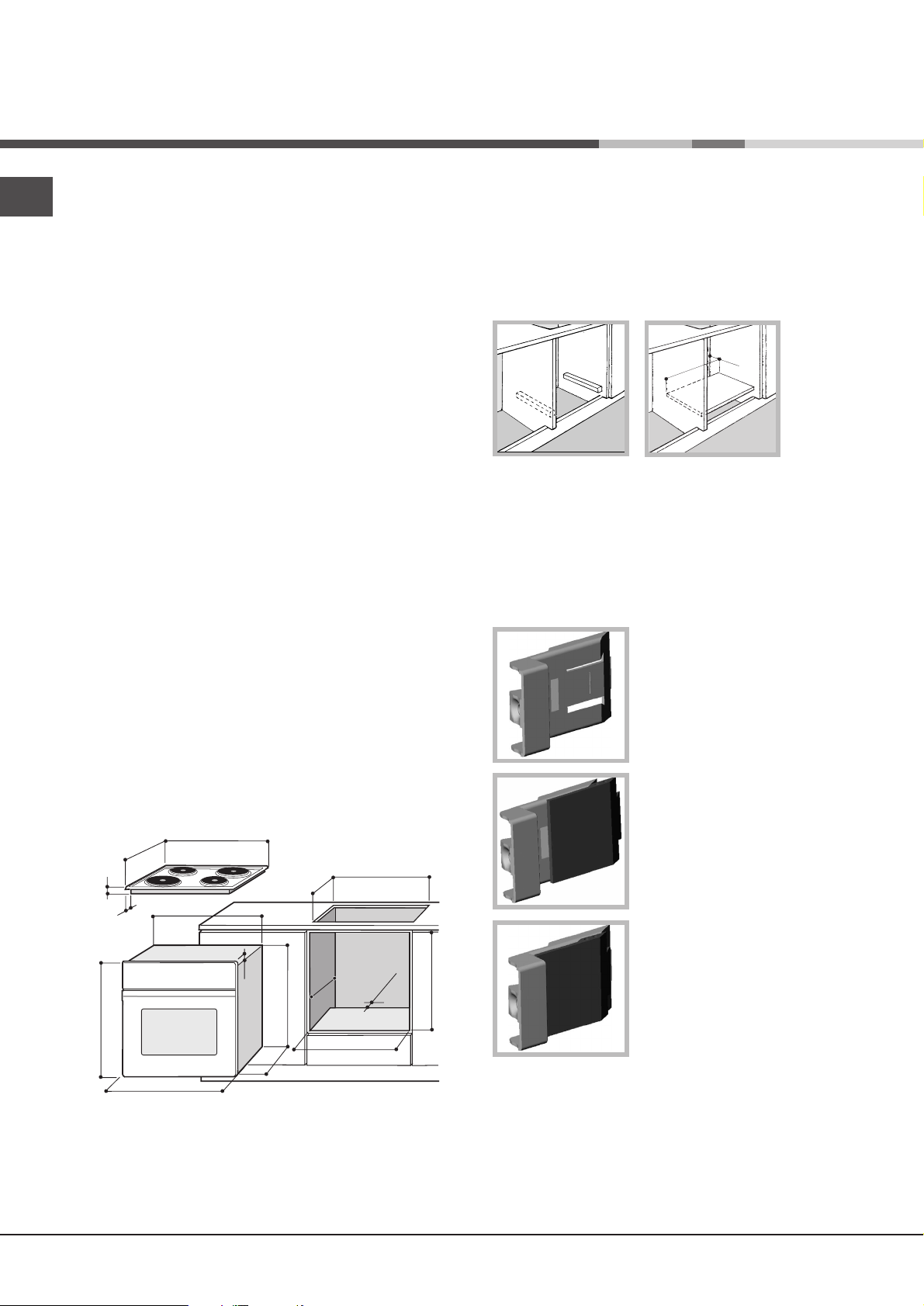
Ventilation
To ensure good ventilation, the back panel of the
cabinet must be removed. It is advisable to install the
oven so that it rests on two strips of wood, or on a
completely flat surface with an opening of at least 45 x
560 mm (
see diagrams
).
45 mm.
560 mm.
Centring and fastening
Position the 4 tabs on the side of the oven according
to the 4 holes of the outer frame. Adjust the tabs
according to the thickness of the cabinet side panel,
as shown below:
thickness of 20 mm: take off
the removable part of the tab
see diagram
(
)
• To install the oven under the counter (
diagram
) and in a kitchen unit, the cabinet must
see
have the following dimensions:
555
580
560
min
+4 -0
min
45
+4 -0
480
23
543
545
547 min
572
558
500
39
15
595
595
! The appliance must not come into contact with
electrical parts once it has been installed.
The consumption indications on the data plate have
been calculated for this type of installation.
min
575-585
thickness of 18 mm: use the
first groove, which has already
been set in the factory (
diagram
)
see
thickness of 16 mm: use the
second groove (
see diagram
Secure the appliance to the cabinet by opening the
oven door and putting 4 screws into the 4 holes of the
outer frame.
! All parts which ensure the safe operation of the
appliance must not be removable without the aid of a
tool.
)
2
Electrical connections
The cooker must be connected to the mains electricity
supply. It is designed to operate with alternating
current at the voltage and frequency indicated on the
data plate (
see the following page
The hob is connected to the cooker using a special
connector.
BUILT-IN HOB
Only on
certain models
WHITE RED YELLOWBLUE GREEN
).
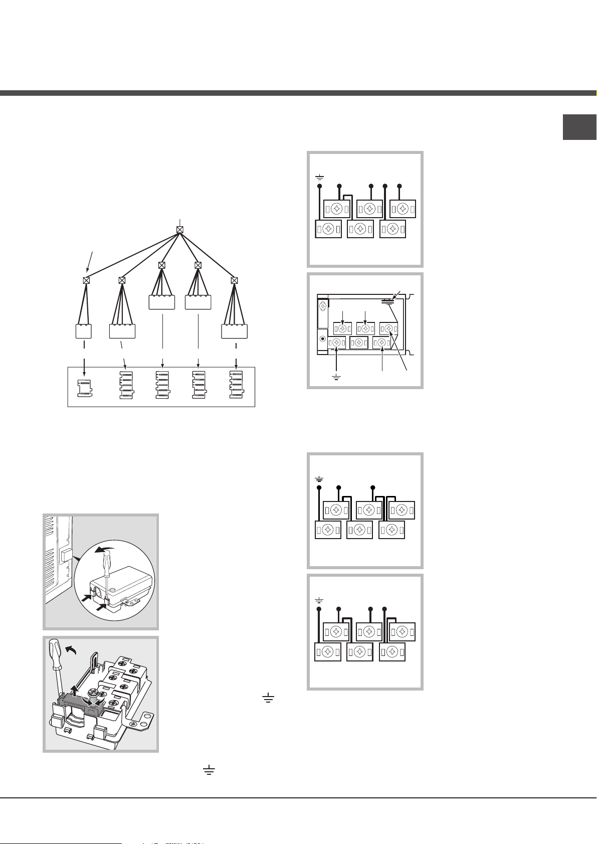
The terminal board is designed for a 400 V threephase connection (
see diagrams below
).
400V 3N~H05RR-F
5x2.5 CEI-UNEL 35363
NL1L3L2
5
3
4
1
2
P
NL2L1
L3
GB
BUILT-IN COOKER
Replace the metal protection after performing all the
necessary hob connections. If the hob is removed
from its position, the red cap which was originally
protecting the red connector must be replaced.
Fitting the power supply cable
1. Open the terminal
board by inserting a
screwdriver into the
side tabs of the cover.
Use the screwdriver as
a lever by pushing it
down to open the cover
see diagram
(
).
2. Loosen the cable
clamp screw and
remove it, using a
screwdriver as a lever
(see figure).
3. Remove the wire
contact screws L-N, then fasten the wires
under the screw heads,
respecting the colour
code: Blue (N), Brown
(L) and Yellow-Green
Verde (
).
If the electrical system has other characteristics (
diagrams below
), carry out the electrical connection
see
using the connection supports provided in the box P.
230V ~H05RR-F 3x4
CEI-UNEL 35363
NL
5
3
4
1
2
400V 2N~H05RR-F 4x4
CEI-UNEL 35363
NL1L2
5
3
4
1
2
3. Secure the power supply cable by fastening the
clamp screw.
4. Close the cover of the terminal board.
3
GB
(
Connecting the supply cable to the mains
Install a standardised plug corresponding to the load
indicated on the data plate (
see side
).
The appliance must be directly connected to the
mains using an omnipolar circuit-breaker with a
minimum contact opening of 3 mm installed between
the appliance and the mains, suitable for the load
indicated and complying with current electrical
regulations (the earthing wire must not be interrupted
by the circuit-breaker). The supply cable must not
come into contact with surfaces with temperatures
higher than 50°C.
! The installer must ensure that the correct electrical
connection has been made and that it is compliant
with safety regulations.
Before connecting to the power supply, make sure
that:
• The appliance is earthed and the plug is compliant
with the law.
• The socket can withstand the maximum power of
the appliance, which is indicated on the data plate
see below
(
).
• The voltage must be in the range between the
values indicated on the data plate (
see below
).
• The socket is compatible with the plug of the
appliance. If the socket is incompatible with the
plug, ask an authorised technician to replace it. Do
not use extension cords or multiple sockets.
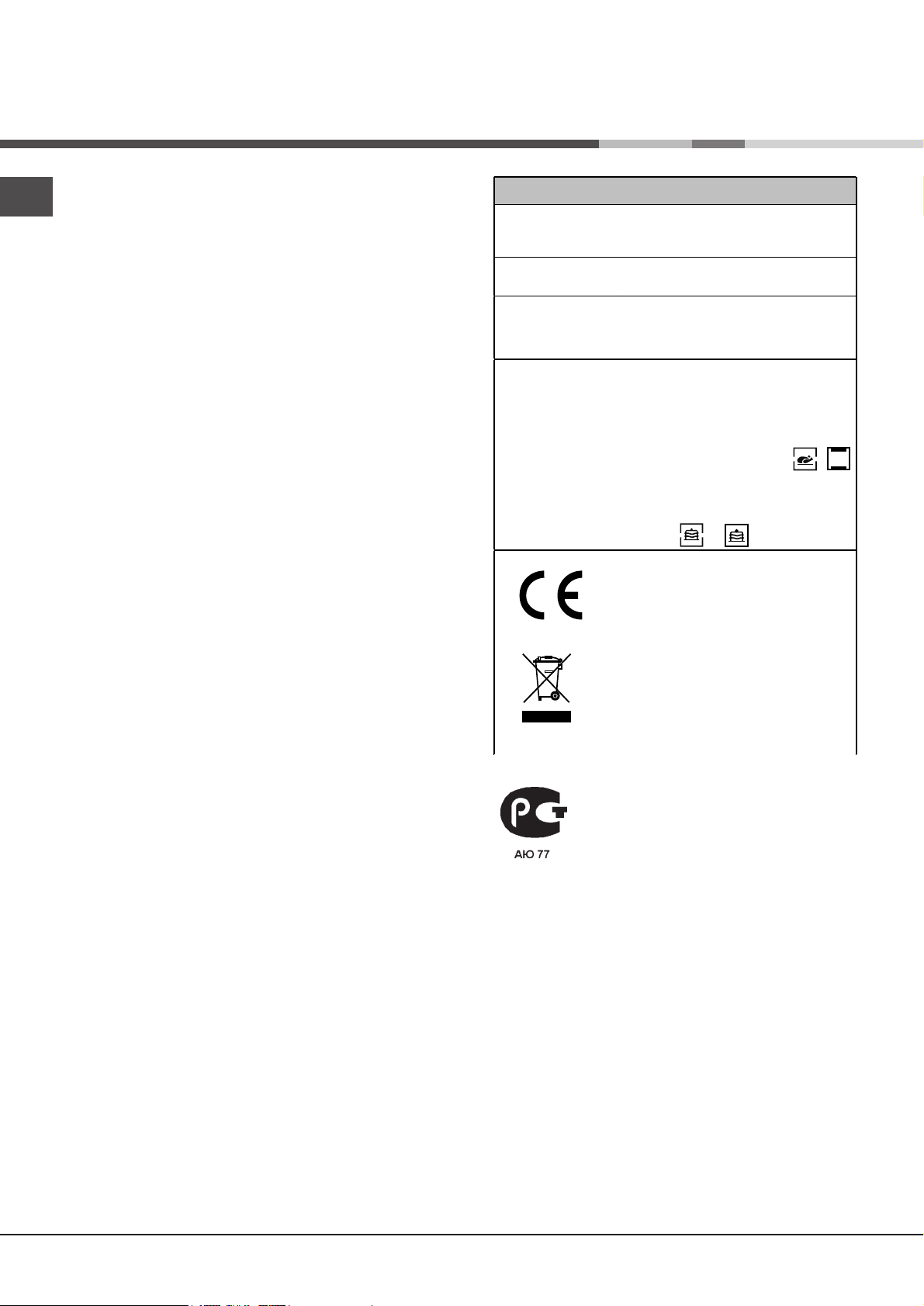
DATA PLATE
width 43.5 cm
Dimensions
Volum e lt. 58
Ele ctri ca l
conn ect ion s
ENERGY LABEL
height 32 cm
dept h 4 1,5 cm
voltage: 230V/400V~ 3N 50/60Hz or
50Hz (see dat a pl ate)
max im um po wer ab sorb ed 1 0800W
or 10700W
Directi v e 20 02/4 0/EC on the lab el of
electri c ov ens .
Standard EN 50304
Ener g y consump tion for Natur al
co nvect ion – heati ng mo de: /
Convecti on mod e.
Declared en er gy consumption f or
Fo rced convecti on Cla ss – heat ing
mode: / Baking.
Th is a pplian c e c onforms to t he
f ol lo wing Europea n Ec onom ic
Community directives:
2006/9 5/EEC o f 12/ 12/0 6 ( Lo w
Voltage) and subsequent
amendments;
- 2004/108/EEC of 15/12/04
(Electromagnetic Compatibility) and
su bsequent am e ndments ;
- 93/6 8/EEC of 22/07/93 and
su bsequent am e ndments .
- 2002/96/EC and su bsequent
amendments.
see data plate)
! Once the appliance has been installed, the power
supply cable and the electrical socket must be easily
accessible.
! The cable must not be bent or compressed.
! The cable must be checked regularly and replaced
by authorised technicians only (
see Assistance
).
! The manufacturer declines any liability should
these safety measures not be observed.
Assistance
Communicating:
• appliance model (Mod.)
• serial number (S/N)
This information is found on the data plate located on the appliance and/or on the packaging.
4

Description of the
appliance
Overall view
Control panel
Control panel
GRILL
DRIPPING PAN
HOTPLATES
indicator light
COOKING
TIMER*
knob
THERMOSTAT
indicator light
GB
GUIDES for the
sliding racks
position 5
position 4
position 3
position 2
position 1
EXTENDABLE
HOTPLATES
knob
EXTENDABLE
HOTPLATES
knob
HOTPLATES
knob
SELECTOR
knob
THERMOSTAT
knob
HOTPLATES
knob
Only on certain models
*
5
Start-up and use
GB
! The first time you use your appliance, heat the
empty oven with its door closed at its maximum
temperature for at least half an hour. Ensure that the
room is well ventilated before switching the oven off
and opening the oven door. The appliance may
produce a slightly unpleasant odour caused by the
burning away of protective substances used during
the manufacturing process.
Starting the oven
1. Select the desired cooking mode by turning the
SELECTOR knob.
2. Select the desired temperature with the
THERMOSTAT knob See the Cooking advice table for
cooking modes and the suggested cooking
temperatures (
3. The THERMOSTAT indicator light indicates that the
oven is heating up to the temperature set.
4. You may do the following during cooking:
- change the cooking mode by turning the SELECTOR
knob
- change the temperature by turning the
THERMOSTAT knob.
- stop cooking by turning the SELECTOR knob to the
“0” position
! Never put objects directly on the oven bottom to
avoid damaging the enamel coating.
! Always place cookware on the rack(s) provided.
see Cooking Modes
).
Cooling ventilation
In order to cool down the external temperature of the
oven, some models are fitted with a cooling fan that
blows out air between the control panel and the oven
door.
!Once the cooking has been completed, the cooling
fan remains on until the oven has cooled down
sufficiently.
Oven light
When selecting
the oven light goes on. It remains on when a cooking
mode is selected.
/ with the SELECTOR knob
Using the cooking timer*
1. To set the buzzer, turn the COOKING TIMER
knob clockwise almost one complete revolution.
2. Turn the knob anticlockwise to set the desired time:
align the minutes shown on the COOKING TIMER
knob with the indicator on the control panel.
3. When the selected time has elapsed, a buzzer
sounds and the oven turns off.
4. When the oven is off the cooking timer can be used
as a normal timer.
! To use the oven manually, in other words when you
do not wish to use the end of cooking timer, turn the
COOKING TIMER knob until it reaches the 9 symbol.
Only on certain models
*
6
Cooking modes
Cooking modes
! A temperature value can be set for all cooking
modes between 60°C and Max, except for the
following modes:
• BARBECUE (recommended: set only to MAX power
level)
• GRATIN (recommended: do not exceed 200°C)
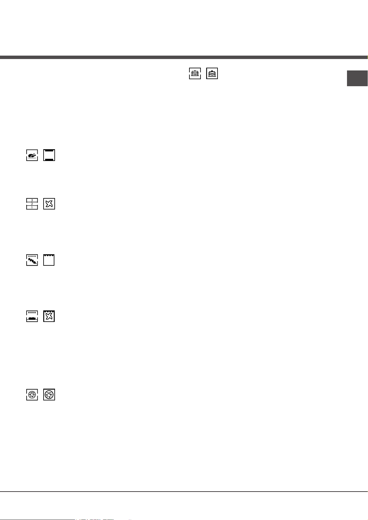
/ TRADITIONAL OVEN mode
Both the top and bottom heating elements will come
on. With this traditional cooking mode, it is best to use
one cooking rack only; if more than one rack is used,
the heat will be distributed unevenly.
/ MULTI-COOKING mode
All the heating elements (top, bottom and circular), as
well as the fan, will come on. Since the heat remains
constant throughout the oven, the air cooks and
browns food uniformly. A maximum of two racks may
be used at the same time.
/ BAKING mode
GB
The rear heating element and the fan come on,
guaranteeing the distribution of heat delicately and
uniformly throughout the oven. This mode is ideal for
baking and cooking temperature sensitive foods
such as cakes that need to rise and to prepare
certain tartlets on 3 shelves simultaneously.
Practical cooking advice
! Do not place racks in position 1 and 5 during fanassisted cooking. Excessive direct heat can burn
temperature sensitive foods.
! In the BARBECUE and GRATIN cooking modes,
place the dripping pan in position 1 to collect cooking
residues (fat and/or grease).
MULTI-COOKING
• Use position 2 and 4, placing the food that requires
more heat on 2.
/ BARBECUE mode
The top heating element comes on.
The high and direct temperature of the grill is
recommended for food that requires high surface
temperature. Always cook in this mode with the oven
door closed.
/ GRATIN mode
The top heating element, as well as the fan, will come
on. This combination of features increases the
effectiveness of the unidirectional thermal radiation of
the heating elements through forced circulation of the
air throughout the oven. This helps prevent food from
burning on the surface, allowing the heat to penetrate
right into the food. Always cook in this mode with the
oven door closed.
/ PIZZA mode
The bottom and circular heating elements, as well as
the fan, will come on. This combination heats the oven
rapidly by producing a considerable amount of heat,
particularly from the bottom element. If you use more
than one rack simultaneously, switch the position of
the dishes halfway through the cooking process.
• Place the dripping pan on the bottom and the rack
on top.
BARBECUE
• Insert the rack in position 3 or 4. Place the food in
the centre of the rack.
• We recommend that you set the maximum power
level. The top heating element is regulated by a
thermostat and may not always be on.
PIZZA MODE
• Use a light aluminium pizza pan. Place it on the
rack provided.
For a crispy crust, do not use the dripping pan
(prevents crust from forming by extending cooking
time).
• If the pizza has a lot of toppings, we recommend
adding the mozzarella cheese on top of the pizza
halfway through the cooking process.
7
GB
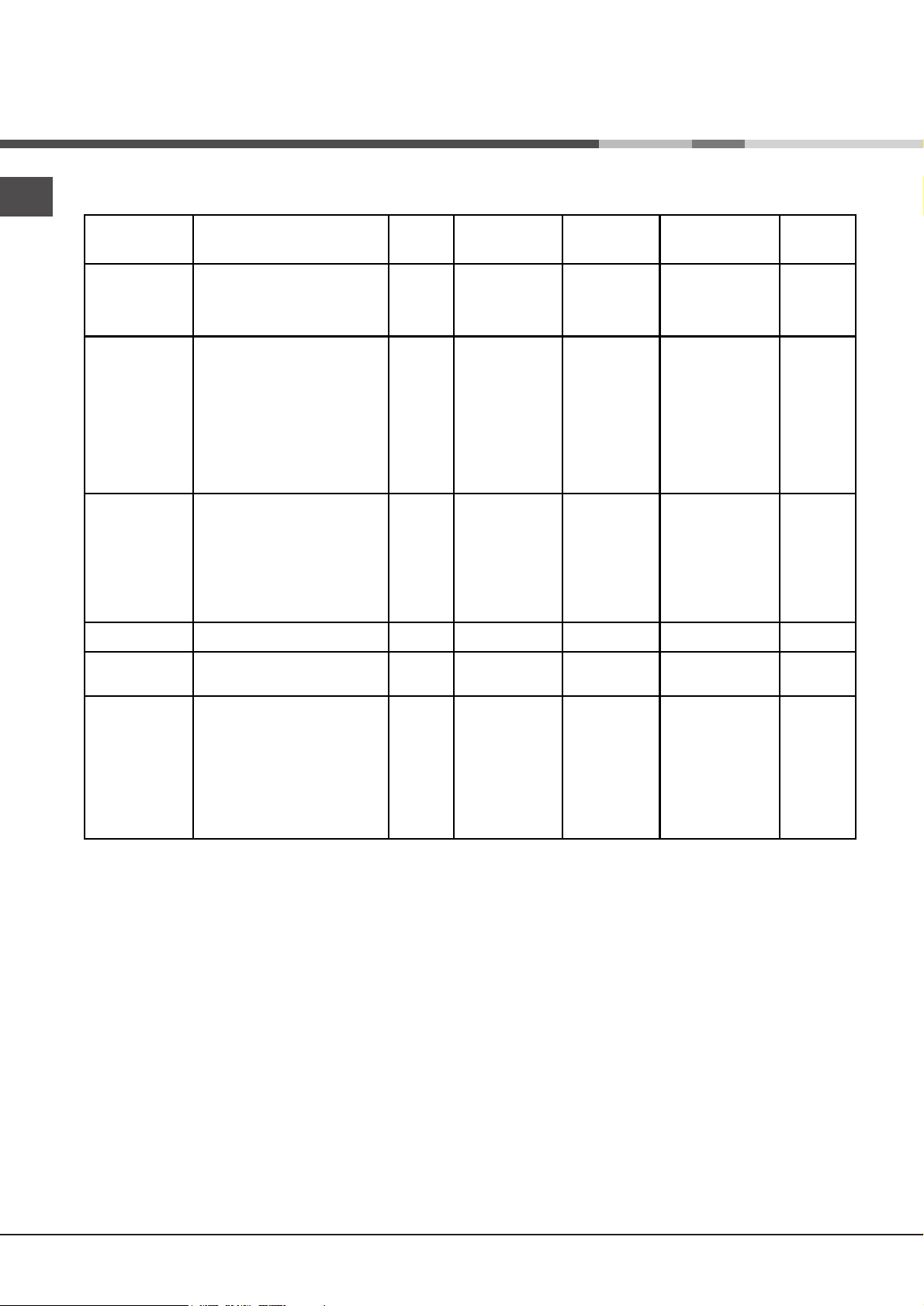
Cooking advice table
Cooking
modes
Convection
Oven
Multi-cooking
Barbecue
Gratin
Pizza Mode
Baking Mode
Duck
Roast veal or beef
Pork roast
Biscuits (short pastry)
Tarts
Pizza (on 2 racks)
Lasagne
Lamb
Roast chicken + potatoes
Mackerel
Plum cake
Cream puffs (on 2 racks)
Biscuits (on 2 racks)
Sponge cake (on 1 rack)
Sponge cake (on 2 racks)
Savoury pies
Soles and cuttlefish
Squid and prawn kebabs
Cod filet
Grilled vegetables
Veal steak
Cutlets
Hamburgers
Mackerels
Toasted sandwiches
Grilled chicken
Cuttlefish
Pizza
Roast veal or beef
Chicken
Tarts
Fruit cakes
Plum cake
Sponge cake
Stuffed pancakes (on 2 racks)
Small cakes (on 2 racks)
Cheese puffs (on 2 racks)
Cream puffs (on 3 racks)
Biscuits (on 3 racks)
Meringues (on 3 racks)
Foods Weight
Rack position Pre-heating
(in kg)
1
1
1
1
1
1
1
1+1
1
1
0.5
0.5
0.5
1
1.5
1
1
1
1
1
1
1
1
n.° 4
1.5
1.5
0.5
1
1
0.5
1
0.7
0.5
1.2
0.6
0.4
0.7
0.7
0.5
3
3
3
3
3
2 and 4
3
2
2 and 4
2
2
2 and 4
2 and 4
2
2 and 4
3
4
4
4
3 or 4
4
4
4
4
4
2
2
3
2
2 or 3
3
2 or 3
3
3
2 and 4
2 and 4
2 and 4
1 and 3 and 5
1 and 3 and 5
1 and 3 and 5
time (min)
15
15
15
15
15
15
10
10
15
10
10
10
10
10
10
15
5
5
5
5
5
5
5
5
5
10
10
15
10
10
15
15
15
15
15
15
15
15
15
15
Recommended
temperature
200
200
200
180
180
230
180
180
200
180
170
190
180
170
170
200
MAX
MAX
MAX
MAX
MAX
MAX
MAX
MAX
MAX
200
200
220
220
180
180
180
180
160
200
190
210
180
180
90
Cooking
time
(minutes)
65-75
70-75
70-80
15-20
30-35
15-20
30-35
40-45
60-70
30-35
40-50
20-25
10-15
15-20
20-25
25-30
8-10
6-8
10
10-15
15-20
15-20
7-10
15-20
2-3
55-60
30-35
15-20
25-30
60-70
20-30
40-45
40-50
25-30
30-35
20-25
15-20
20-25
20-25
180
8
 Loading...