

Page 1
Operating Instructions
HOB
GB
English, 1
RS
Русский, 11
CISTD 640 S /HA
CISTD 640 S IX/HA
7HTD 640 IX/HA
7HTD 640 S IX/HA
Contents
GB
Installation, 2-5
Positioning
Electrical connection
Gas connection
Data plate
Burner and nozzle specifications
Description of the appliance, 6
Overall view
Start-up and use, 7
Practical advice on using the burners
Precautions and tips, 8
General safety
Disposal
Maintenance and care, 9
Switching the appliance off
Cleaning the appliance
Gas tap maintenance
Troubleshooting, 10
Page 2
Installation
A
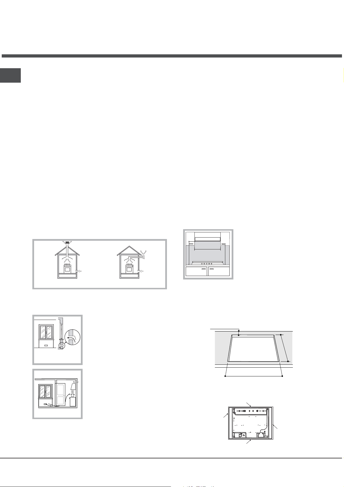
Examples of ventilation holes
for comburant air.
GB
Before operating your new appliance please read this
instruction booklet carefully. It contains important information
for safe use, installation and care of the appliance.
Please keep these operating instructions for future
reference. Pass them on to possible new owners of the
appliance.
Positioning
Keep packaging material out of the reach of children. It
can become a choking or suffocation hazard (see
Precautions and tips).
The appliance must be installed by a qualified professional
according to the instructions provided. Incorrect installation
may cause harm to people and animals or may damage
property.
This unit may be installed and used only in permanently
ventilated rooms in accordance with British Standard Codes
Of Practice: B.S. 6172 / B.S. 5440, Par. 2 and B.S. 6891
Current Editions. The following requirements must be
observed:
The room must be equipped with an air extraction system
that expels any combustion fumes. This may consist of a
hood or an electric fan that automatically starts each time
the appliance is switched on.
also be equipped with vents to allow gas to escape in
the event of a leak. As a result LPG cylinders, whether
partially or completely full, must not be installed or
stored in rooms or storage areas that are below ground
level (cellars, etc.). It is advisable to keep only the
cylinder being used in the room, positioned so that it is
not subject to heat produced by external sources
(ovens, fireplaces, stoves, etc. ) which could raise the
temperature of the cylinder above 50°C.
Fitting the appliance
Gas and mixed hobs are manufactured with type X
degree protection against overheating. The following
precautions must be taken when installing the hob:
Kitchen cabinets adjacent to the appliance and taller
than the top of the hob must be at least 600 mm from
the edge of the hob.
Hoods must be installed according to their relative
installation instruction manuals and at a minimum
distance of 650 mm from the hob.
Place the wall cabinets adjacent to the hood at a
minimum height of 420 mm from the hob (see figure).
If the hob is installed beneath a
wall cabinet, the latter must be
600mm min.
situated at a minimum of 700 mm
above the hob (see figure).
700mm min.
600mm min.
In a chimney stack or branched flue.
(exclusively for cooking appliances)
Directly to
the Outside
The room must also allow proper air circulation, as air is
needed for combustion to occur normally. The flow of air
must not be less than 2 m
3
/h per kW of installed power.
The air circulation system may
take air directly from the outside
by means of a pipe with an inner
cross section of at least 100 cm
the opening must not be
vulnerable to any type of
blockages.
Adjacent
Room
Room to be
Vented
The system can also provide the
air needed for combustion
indirectly, i.e. from adjacent rooms
fitted with air circulation tubes as
described above. However, these
Enlarging the ventilation slot
between window and floor.
rooms must not be communal
rooms, bedrooms or rooms that
may present a fire hazard.
Liquid petroleum gas sinks to the floor as it is heavier
than air. Therefore, rooms containing LPG cylinders must
The installation cavity should have the dimensions
indicated in the figure. Fastening hooks are provided,
allowing you to fasten the hob to tops that are between
20 and 40 mm thick. To ensure the hob is securely
fastened to the top, we recommend you use all the
hooks provided.
55
mm
2
;
555
mm
475
m
m
Before fastening the cooktop in place, position the seal
(supplied) along the perimeter of the countertop, as
shown in the figure.
2
Page 3
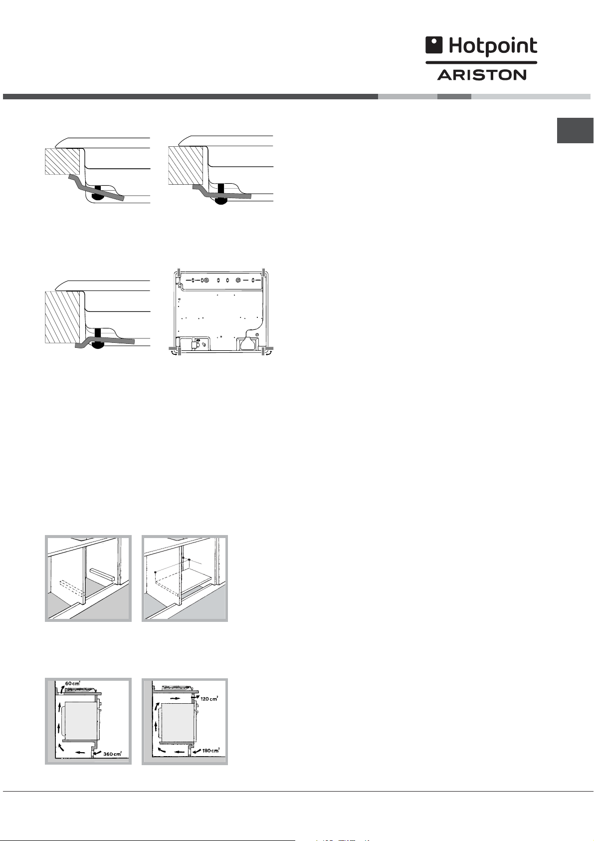
Hook fastening diagram
Hooking position Hooking position
for top H=20 mm for top H=30 mm
Electrical connection
Hobs equipped with a three-pole power supply cable are
designed to operate with alternating current at the voltage
and frequency indicated on the data plate (this is located on
the lower part of the appliance). The earth wire in the cable
has a green and yellow cover. If the appliance is to be
installed above a built-in electric oven, the electrical
connection of the hob and the oven must be carried out
separately, both for electrical safety purposes and to make
extracting the oven easier.
GB
Front
Hooking position Back
for top H=40 mm
Use the hooks contained in the accessory pack
Where the hob is not installed over a built-in oven, a
wooden panel must be installed as insulation. This
must be placed at a minimum distance of 20 mm from
the lower part of the hob.
Ventilation
To ensure adequate ventilation, the back panel of the
cabinet must be removed. It is advisable to install the
oven so that it rests on two strips of wood, or on a
completely flat surface with an opening of at least 45 x
560 mm (see diagrams).
45 mm.
.
m
560 m
Where a hob is installed above an oven without a forced
ventilation cooling system, adequate ventilation must be
provided inside the cabinet by means of air holes through
which air can pass (see figure).
Connecting the supply cable to the mains
Install a standardised plug corresponding to the load
indicated on the data plate.
The appliance must be directly connected to the mains using
an omnipolar circuit-breaker with a minimum contact opening
of 3 mm installed between the appliance and the mains. The
circuit-breaker must be suitable for the charge indicated and
must comply with current electrical regulations (the earthing
wire must not be interrupted by the circuit-breaker). The
supply cable must not come into contact with surfaces with
temperatures higher than 50°C.
The installer must ensure that the correct electrical
connection has been made and that it is compliant with
safety regulations.
Before connecting to the power supply, make sure that:
The appliance is earthed and the plug is compliant with
the law.
The socket can withstand the maximum power of the
appliance, which is indicated on the data plate.
The voltage is in the range between the values indicated
on the data plate.
The socket is compatible with the plug of the appliance. If
the socket is incompatible with the plug, ask an
authorised technician to replace it. Do not use extension
cords or multiple sockets.
Once the appliance has been installed, the power supply
cable and the electrical socket must be easily accessible.
The cable must not be bent or compressed.
The cable must be checked regularly and replaced by
authorised technicians only (see Assistance).
The manufacturer declines any liability should these safety
measures not be observed.
Gas connection
The appliance should be connected to the main gas supply
or to a gas cylinder in compliance with current national
regulations. Before carrying out the connection, make sure
the cooker is compatible with the gas supply you wish to
use. If this is not the case, follow the instructions indicated in
the paragraph Adapting to different types of gas.
When using liquid gas from a cylinder, install a pressure
regulator which complies with current national regulations.
3
Page 4
GB
Check that the pressure of the gas supply is consistent
with the values indicated in Table 1 (Burner and nozzle
specifications). This will ensure the safe operation and
longevity of your appliance while maintaining efficient
energy consumption.
Connection with a rigid pipe (copper or steel)
Connection to the gas system must be carried out in
such a way as not to place any strain of any kind on the
appliance.
There is an adjustable L-shaped pipe fitting on the
appliance supply ramp and this is fitted with a seal in
order to prevent leaks. The seal must always be replaced
after rotating the pipe fitting (seal provided with
appliance). The gas supply pipe fitting is a threaded 1/2
gas cylindrical male attachment.
Connecting a flexible jointless stainless steel pipe to a
threaded attachment
The gas supply pipe fitting is a threaded 1/2 gas
cylindrical male attachment.
These pipes must be installed so that they are never longer
than 2000 mm when fully extended. Once connection has
been carried out, make sure that the flexible metal pipe
does not touch any moving parts and is not compressed.
Only use pipes and seals that comply with current
national regulations.
Checking the tightness of the connection
When the installation process is complete, check the
pipe fittings for leaks using a soapy solution. Never use a
flame.
Adapting to different types of gas
To adapt the hob to a different type of gas other than
default type (indicated on the rating plate at the base of
the hob or on the packaging), the burner nozzles should
be replaced as follows:
1. Remove the hob grids and slide the burners off their
seats.
2. Unscrew the nozzles using a 7 mm socket spanner, and
replace them with nozzles for the new type of gas (see
table 1 Burner and nozzle characteristics).
3. Reassemble the parts following the above procedure in
the reverse order.
4. Once this procedure is finished, replace the old rating
sticker with one indicating the new type of gas used.
Sticker are available from any of our Service Centres.
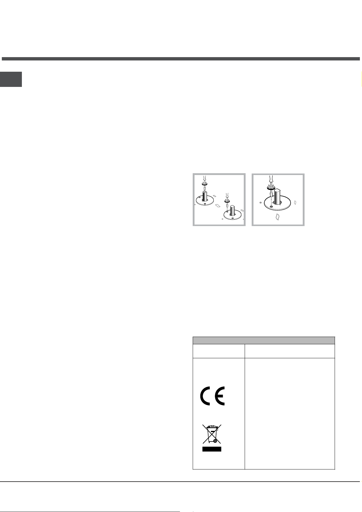
Adjusting the burners primary air :
Does not require adjusting.
Setting the burners to minimum:
1. Turn the tap to the low flame position.
2. Remove the knob and adjust the adjustment screw,
which is positioned in or next to the tap pin, until the
flame is small but steady.
3. Having adjusted the flame to the required low setting,
while the burner is alight, quickly change the position of
the knob from minimum to maximum and vice versa
several times, checking that the flame does not go out.
4. Some appliances have a safety device (thermocouple)
fitted. If the device fails to work when the burners are
set to the low flame setting, increase this low flame
setting using the adjusting screw.
5. Once the adjustment has been made, replace the seals
on the by-passes using sealing wax or a similar
substance.
If the appliance is connected to liquid gas, the regulation
screw must be fastened as tightly as possible.
Once this procedure is finished, replace the old rating
sticker with one indicating the new type of gas used.
Stickers are available from any of our Service Centres.
Should the gas pressure used be different (or vary
slightly) from the recommended pressure, a suitable
pressure regulator must be fitted to the inlet pipe (in order
to comply with current national regulations).
DATA PLATE
Electrical
See data plate
connections
This appliance conforms to the
following European Economic
Community directives:
-2006/95/EEC dated 12/12/06
(Low Voltage) and subsequent
amendments
- 2004/108/EEC dated 15/12/04
(Electromagnetic Compatibility)
and subsequent amendments
- 93/68/EEC dated 22/07/93 and
subsequent amendments.
- 90/336/EEC dated 29/06/90
(Gas) and subsequent
amendments.
- 2002/96/EC and subsequent
amendments.
4
Page 5
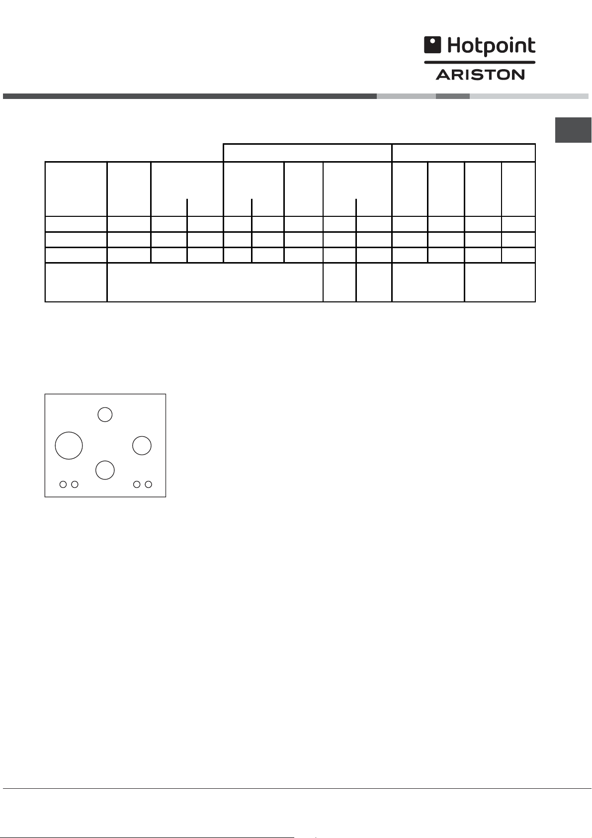
Burner and nozzle specifications
GB
Table 1
Burner Diameter
(mm)
Fast (R)
Semi Fast (S)
Auxiliary (A)
Supply
Pressures
100 3,00 0,70 41 39 86 218 214 116 286 143 286
75 1,65 0.40 30 28 64 120 118 96 157 105 157
55 1,00 0,40 30 28 50 73 71 79 95 80 95
Thermal power
kW (p.c.s.*)
Nomin. Ridot. (1) (mm) *** ** (mm) (mm)
Nominal (mbar)
Minimum (mbar)
Maximum (mbar)
By-Pass
1/100
(mm)
* At 15°C and 1013 mbar-dry gas
** Propane P.C.S. = 50.37 MJ/kg.
*** Butane P.C.S. = 49.47 MJ/kg.
Natural P.C.S. = 37.78 MJ/m
3
(1) Only for appliances with the security device.
A
Liquid Gas Natural Gas
Nozzle
1/100
28-30
20
35
Flow*
g/h
37
25
45
Nozzle
1/100
20
17
25
Flow*
l/h
Nozzle
1/100
Flow*
l/h
13
6,5
18
RS
S
CISTD 640 S/HA
CISTD 640 S IX/HA
7HTD 640 IX/HA
7HTD 640 S IX/HA
5
Page 6
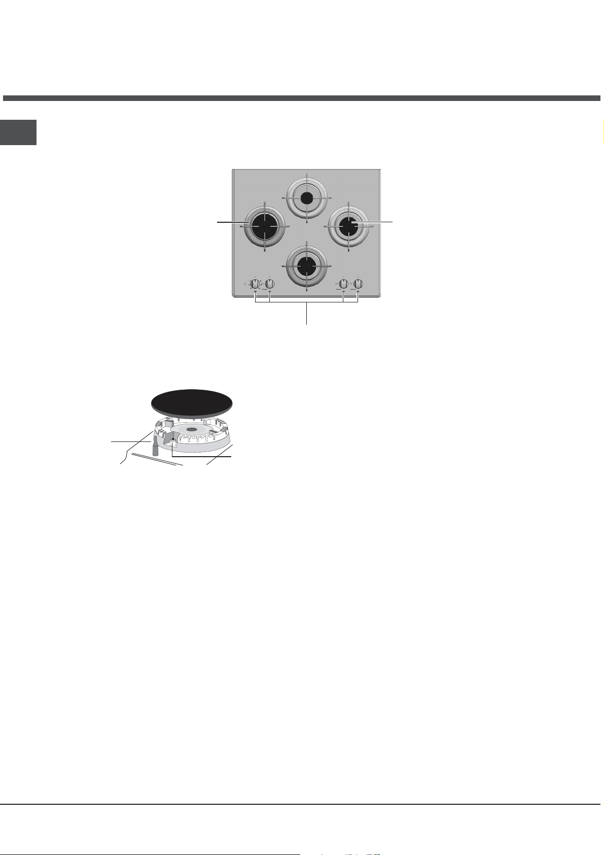
Description of the
appliance
GB
Overall v iew
Support Grid for
COOKWARE
GAS BURNERS
Control Knobs for
GAS BURNERS
SAFETY
DEVICES *
GAS BURNERS differ in size and power. Use the
diameter of the cookware to choose the most
appropriate burner to cook with.
Control Knobs for GAS BURNERS adjust the
power or the size of the flame.
GAS BURNER ignition* enables a specific burner
to be lit automatically.
SAFETY DEVICE* stops the gas flow if the flame
is accidentally extinguished.
Ignition for
GAS BURNERS *
Only available on certain models.
*
6
Page 7

Start-up and use
The position of the corresponding gas burner is shown
on every knob.
Gas burners
Each burner can be adjusted to one of the following
settings using the corresponding control knob:
Off
Maximum
Minimum
To turn on one of the burners, place a lighted match or
lighter near the burner, press the knob all the way in and
turn it anti-clockwise to the "High" setting.
On those models fitted with a safety device (F), the knob
must be pressed in for about 6 seconds until the device
that keeps the flame lit warms up.
On those models fitted with an ignitor, the ignition button,
identified by the
then the corresponding knob pushed all the way in and
turned anti-clockwise to the "High" setting.
Some models are equipped with an ignition button
incorporated into the control knob. If this is the case, the
ignitor is present, but not the button.
To light a burner, simply press the corresponding knob all
the way in and then turn it anti-clockwise to the "High"
setting, keeping it pressed in until the burner lights.
symbol, must first be pressed and
Practical advice on using the burners
GB
To ensure the burners operate efficiently:
Use appropriate cookware for each burner (see table)
so that the flames do not extend beyond the bottom of
the cookware.
Always use cookware with a flat base and a cover.
When the contents of the pan reach boiling point, turn
the knob to minimum.
Burner ø Cookware diameter (cm)
Fast (R) 24 - 26
Semi Fast (S) 16 - 20
Auxiliary (A) 10 - 14
To identify the type of burner, refer to the designs in the
section entitled, "Burner and Nozzle Specifications".
If a flame is accidentally extinguished, turn off the control
knob and wait for at least 1 minute before trying to relight
it.
To switch off the burner, turn the knob in a clockwise
direction until it stops (when reaches the position).
7
Page 8

Precautions and tips
GB
This appliance has been designed and
manufactured in compliance with international safety
standards. The following warnings are provided for
safety reasons and must be read carefully.
General safety
This is a class 3 built-in appliance.
Gas appliances require regular air exchange to
maintain efficient operation. When installing
the hob, follow the instructions provided
paragraph on Positioning the appliance.
These instructions are only valid for the
countries whose symbols appear in the manual
and on the serial num
The appliance was designed for domestic use
inside the home and is not intended for
commercial or industrial use.
The appliance must not be installed outdoors, even
in covered areas. It is extremely dangerous to
leave the appliance exposed to rain and storms.
Do not touch the appliance with bare feet or with
wet or damp hands and feet.
The appliance must be used by adults only, to
cook food according to the instructions in this
manual.
Ensure that the power supply cables of other
electrical appliances do not come into contact
with the hot parts of the oven.
The openings used for ventilation and dispersion
of heat must never be covered.
Always make sure the knobs are in the l/
position when the appliance is not in use.
When unplugging the appliance always pull the plug
from the mains socket, do not pull on the cable.
Never carry out any cleaning or maintenance work
without having detached the plug from the mains.
ber plate.
in the
¡
In case of malfunction, under no circumstances
should you attempt to repair the appliance
yourself. Repairs carried out by inexperienced
persons may cause injury or further
malfunctioning of the appliance. Contact a Service
Centre (see Assistance).
Always make sure that pan handles are turned
towards the centre of the hob in order to avoid
accidental burns.
Do not close the glass cover (if present) when the
gas burners are still hot.
Do not use unstable or deformed pans.
The appliance should not be operated by people
(including children) with reduced physical,
sensory or mental capacities, by inexperienced
individuals or by anyone who is not familiar with
the product. These individuals should, at the very
least, be supervised by someone who assumes
responsibility for their safety or receive
preliminary instructions relating to the operation of
the appliance.
Do not let children play with the appliance.
Disposal
When disposing of packaging material: observe
local legislation so that the packaging may be
reused.
The European Directive 2002/96/EC on Waste
Electrical and Electronic Equipment (WEEE),
requires that old household electrical appliances
must not be disposed of in the normal unsorted
municipal waste stream. Old appliances must be
collected separately in order to optimise the
recovery and recycling of the materials they
contain and reduce the impact on human health
and the environment. The crossed out wheeled
bin symbol on the product reminds you of your
obligation, that when you dispose of the
appliance it must be separately collected.
Consumers may take their old appliance to public
waste collection areas, other communal collection
areas, or if national legislation allows return it to a
retailer when purchasing a similar new product.
All major household appliance manufacturers are
active in the creation of systems to manage the
collection and disposal of old appliances.
8
Page 9

Maintenance and care
Switching the appliance off
Disconnect your appliance from the electricity
supply before carrying out any work on it.
Cleaning the appliance
Do not use abrasive or corrosive detergents such
as stain removers, anti-rust products, powder
detergents or sponges with abrasive surfaces: these
may scratch the surface beyond repair.
! Do not use stainless steel flame spreaders,
Never use steam cleaners or pressure cleaners on
the appliance.
bread toasters or meat grills over gas flames.
GB
It is usually enough to wash the hob with a damp
sponge and dry it with absorbent kitchen roll.
The removable parts of the burners should be
washed frequently with warm water and soap and
any burnt-on substances removed.
For hobs which ligth automatically, the terminal
part of the electronic instant lighting devices
should be cleaned frequently and the gas outlet
holes should be checked for blockages.
Stainless steel can be marked by hard water that
has been left on the surface for a long time, or by
aggressive detergents containing phosphorus.
After cleaning, rinse and dry any remaining drops
of water.
Gas tap maintenance
Over time, the taps may become jammed or difficult
to turn. If this happens, the tap must be replaced.
This procedure must be performed by a
qualified technician authorised by the
manufacturer.
9
Page 10

GB
Troubleshooting
It may happen that the appliance does not function properly or at all. Before calling the service centre for
assistance, check if anything can be done. First, check to see that there are no interruptions in the gas and
electrical supplies, and, in particular, that the gas valves for the mains are open.
Problem
The burner does not light or the flame is not
even around the burner.
The flame dies in models with a safety device.
The burner does n
minimum.
The cookware is unstable.
If, despite all these checks, the hob does not function properly and the problem persists, call the nearest
Customer Service Centre. Please have the following information handy:
The appliance model (Mod.).
The serial number (S/N).
This information can be found on the data plate located on the appliance and/or on the packaging.
ot remain lit when set to
Possible causes/Solution
The gas holes on the burner are clogged.
All the movable parts that make up the burner are
mounted correctly.
There are draughts near the appliance.
You pressed the knob all the way in.
You keep the knob pressed in long enough to activate the
safety device.
The gas holes are not blocked in the area corresponding
to the safety device.
The gas holes are not blocked.
There are no draughts near the appliance.
The minimum setting has been adjusted properly.
The bottom of the cookware is perfectly flat.
The cookware is positioned correctly at the centre of the
burner.
The pan support grids have been positioned correctly.
Never use unauthorised technicians and never accept replacement parts which are not original.
10
Page 11

Руководство по
эксплуатации
GB
English, 1
CISTD 640 S /HA
CISTD 640 S IX/HA
7HTD 640 IX/HA
7HTD 640 S IX/HA
RS
Русский, 11
ВАРОЧНАЯ ПАНЕЛЬ
Содержание
RS
Монтаж, 12-15
Ðàñположенèå
Ýëåêòðè÷åñêîå ïîäêлюченèå
Ïîäñîåäèíåíèå ê газопроводó
Ïàñпортная таблè÷êà
Õàðàêòåðèñòèêè êонфороê è ôîðñóíîê
Описание изделия, 16
Общии вид
Включение и эксплуатация, 17
Ïðàêòè÷åñêèå ñоветы по эêñïëóàòàöèè êонфороê
Предосторожности и рекомендации, 18
Îáùèе требованèÿ ê безопаñíîñòè
Óòèëèçàöèÿ
Техническое обслуживание и уход, 19
Îòêлюченèå ýëåêòðîïèòàíèÿ
×èñòêà èçäåëèÿ
Óõîä çà ðóêîÿòêàìè газовоè варочноè панелè
Неисправности и методы их
устранения, 20
Page 12

Ìонтаж
RS
Важно сохранèть данное рóêîâîäñòâî äëÿ åãî
ïîñëåäóþùèõ êîíñóльтацèè. Â ñëóчае продажè,
передачè èçäåëèÿ èëè ïðи переезде на новое место
æèòåëüñтва необходèмо проверèть, чтобы рóêîâîäñòâî
îñтавалоñü âìåñòå ñ èçäåëèем, для того чтобы его
новыè владелец мог ознаêîìèòüñÿ ñ ïðàâèëàìè
ýксплуатации è с соответñòâóþù
èìè
ïðåäóпрежденèÿìè.
Âíèмательно прочèòàèòå èíñòðóêöèè: â íèх
содержатся важные сведения об установке изделия,
его эксплуатации и безопасности.
Расположение
Не разрешаите детям èграть ñ óïàêовочнымè
материалами. Упаковка должна быть уничтожена в
соответствии с правилами раздельного сбора мусора
(см. Предосторожности и рекомендации).
Установкà èçäåëèÿ ïðîèçâîäèòñÿ â ñоответñòâèè ñ
данными инструкциями квалифицированными
ñïåöèалистамè. Неправèëüíûè
ñòàòü ïðè÷èíîè повреждения иìóùåñòâà è ïðè÷èíèòü
óщерб людям è домашнèì æèвотным.
Данное èçäåëèе может быть установлено è
èñпользоватьñÿ òîëüêо в помещенèÿõ ñ ïîñтояннои
âåíòèëÿöèåè â ñоответñòâèè ñ положенèÿìè ñëåäóþùèõ
Норматèâîâ (British Standards Codes Of Practice): B.S.
6172/B.S. 5440, Ïàð. 2 è B.S. 6891 Дополненные
выпóñêè. Должны быть ñоблюдены ñëåäóþùèå
требованèя:
В помещенèè должно èìåòüñÿ âåíòèëÿöèонное
отверñòèÿ äëÿ удаленèÿ â àòìîñôåðó ïðîäуктов
ñгоранèя. Дымодаленèе должно оñóùåñтвлятьñÿ
ïîñðåäñтвом выятжного зонта èëè
ýëåêтровентèлятора, автоматè÷åñêè âключающегоñÿ
êàæäûè ðàç ïðè âключенèè èçäåëèÿ.
монтаж èçäåëèя может
пожароопаñíûìè èëè ñпальнямè.
Ñæиженныи газ пропан-бутан тяжелее воздуха и
ñледовательно заста
èâàåòñÿ âíèçó. Ïî ýòîè ïðè÷èíå
помещенèÿ, â êоторых óñтановлены баллоны ñ ÑÏÃ
(ñæèженным прèродным газом) должны èìåòü
âåíòèëÿöèонные отверñòèÿ âíèçó, ñообщающèåñÿ ñ
óëèöåè, äëÿ óдаленèя возможных óòå÷åê ãàçà.
Поэтомó баллоны ñ СПГ должны быть опорожнены
èëè îставатьñÿ ÷àñòèчно заполненнымè; îíè íå
должны размещатьñÿ èëè õðàíèòüñя в подземных
помещенèÿõ
è õðàíèëищах (подвалах, è ò.ä.). Ñëåäóåò
держать в помещенèè òîëüêî îäèн рабочèè баллон,
раñположенныè òàким образом, чтобы он не
подвергалñя прямомó воздеèñòâèþ èñòî÷íèêов тепла
(печеè, êàìèíîâ è ò.ä.), êоторые могóò ïðèâåñòè ê его
нагреву свыше 50°C.
Âстроенныи монтаж
Газовые è ãàçî-ýëåêòðè÷åñêèе варочные панелè
îснащены ñèñòåìîè çàùèты от чрезмерного перегрева
êëàññа Х, поэтомó êóхонная плèта может быть óñтановлена
рядом êóхоннымè мебельнымè элементамè, âûñîòà
êоторых не превышает óровень варочноè панелè. Äëÿ
ïðàâèльного монтажа варочноè панелè необходèìî
ñоблюдать ñëåäóþùèе меры предоñторожноñòè:
Êухонные элементы, расположенные рядом с
варочноè панелью, выñîòà êоторых превышает
óровень варочноè панелè, должны находèòüñÿ íà
ðàññòîÿíèè не менее 600 мм от ее
êðàÿ.
Вытяжноè зонт должен быть óñтановлен ñîãëàñíî
ñоответñòâóþùåìó òåõíè÷åñêîìó ðóêîâîäñòâó íà
ðàññòîÿíèè от варочноè панелè не менее 650 мм.
Íàâåñíûå êóхонные шêàôû, ïðèлегающèå ê êóхонноè
вытяжêе, должны раñполагатьñÿ íà âûñîòå 420 ìì
îò êóхонного топа (см. схему).
Åñëи варочная панель
óñтанавлèâàåòñÿ ïîä íàâåñíûì
600mm min.
700mm min.
øêàôîì, ïîñëåäíèè должен
раñполагатьñÿ íà âûñоте не
менее 700 мм от êóхонного топа
600mm min.
(см. схему).
В помещенèè должен быть обеñпечен доñтаточныè
ïðèòîê âîçäóха для надлежащего горенèÿ. Ðàñõîä
âîçäóха, необходè
ìûè для горенèя, должен быть не
менее 2 м<+>3/чаñ íà êÂò
óñтановленноè мощноñòè.
Ñистема притока воздуха может
çàáèðàòü âîçäóõ
íåïîñðåäñтвенно èç àòìîñôåðû,
ñíàðóæè здания через воздуховод
ñ проходным ñå÷åíèем не менее
2
, êоторыè не может быть
10 ñì
ñëó÷àèíî çàñîðåí.
Èëè æå âîçäóх для горенèя может
поступать èç ñмежных
помещенèè, îñнащенных
вентèëÿöèонным отверñòèем,
выходящèì â àòìîñôåðó, êàê
îïèñàíî âûøå, ïðè óñëîâèè, ÷òî
ýòè помещенèя не являютñÿ
зонамè общего пользованèÿ,
12
Ðазмеры ниøè êóхонного элемента должны
ñоответñтвовать схеме. В крепежныи комплект входят
êрепежные êðþêè äëÿ êрепленèя варочноè панелè íà
êóхонноè рабочеè поверхносòè толщинои îò 20 äî 40 ìì.
Для надежного крепленèя варочноè панелè
ðåêомендóåòñÿ èñпользовать вñå ïðèлагающèåñÿ êðþêè.
55
mm
475
m
m
555
mm
Перед êрепленèåì êóхонного топа óñтановèòå
óплотненèе (прилагается) по периметру варочнои
панелè, êàê ïîêазано на сõåìå.
Page 13

Ñõåìа крепления крюков
Монтаж êðþêà äëÿ
êóхонного топа H=20 ìì
Монтаж êðþêà äëÿ
êóхонного топа H=30 ìì
Спереди
Монтаж êðþêà äëÿ
êóхонного топа H=
Сзади
40 ìì
Èñпользóèòå êðþêè èç êомплеêòà «âñпомогательные
ïðèнадлежноñòè»
Åсли варочная панель не óñтанавлèâàåòñÿ ñâåðõó
âñтроенного дóхового шêафа, необходèìî âñòàâèòü
деревяннóю панель в êà÷åñòâå èзоляцèè. Эта
панель должна быть óñтановлена на раññòîÿíèè не
менее 20 мм от нèæíåè ÷àñòи варочнои панели.
Âåíòèëÿöèÿ
Äëÿ îáåñпеченèя надлежащеè âåíòèëÿöèè необходèìî
ñнять заднюю панель кухонного элемента.
Ðåêомендóåòñÿ óñтановèòü äóховои шкаф на два
деревянных брóñêà èëè íà ñплошное оñнованèå ñ
отверñòèåì äèаметром не менее 45 х 560 мм (ñì
схемы).
45 mm.
.
m
560 m
Åñëи варочная панель óñтанавлèâàåòñÿ ñâåðõó
âñтроенного дóхового шêàôà, íå îñнащенного
прèíóäительнои охладительнои вентиляциеи, для
надлежаще
è âåíòèëÿöèè âíóòðè êóхонного элемента
необходèмо проделать вентèëÿöèонные отверñòèÿ äëÿ
öèðкуляции воздóõà (см схемы).
Электрическое подключение
Варочные панелè, îñнащенные трехполюñíûì
ñетевым êабелем, раñ÷èòàíû íà ôóíêöèîíèрованиå ñ
переменным тоêîì ñ напряженèåì è ÷àстотоè
ýëåêòðîïитаниÿ, óêазаннымè íà ïàñпортноè òàáëè÷êå
(ðàñположенноè ñíèçу варочнои панели). Провод
заземленèÿ ñетевого êабеля èмеет желто-зеленыè
öâåò. Â ñëучае установêè варочнои панели сверхó
äóхового ш
элеêòðè÷åñêîå ïîäñîåäèíåíèе варочноè панелè è
äóхового шêафа должно выполнятьñя раздельно по
прè÷èнам безопаñíîñòè, à òàê æå äëÿ ëåãêîãî ñúåìà
äóхового шêàôà.
Ïîäñîåäинение ñåòåâîãî êàáåëÿ èçäåëèÿ ê
ñåòè ýëåêòðîïèòàíèÿ
Óстановите на сетевои кабель нормализованную
øòåïñåëüíóþ âèëêó, ðàñ÷èòàííóþ íà íàãðóçêó, óêазаннóþ
на заводñêîè òàáëè÷êå.
Изделèе должно быть подñîåäèíåíî ê ñåòè напрямóþ
ïðè помощè многополюñíîãî âûêлючателя
мèíèмальным раññòîÿíèåì ìåæäó êîíòàêòàìè 3 ìì,
óñтановленного междó èçäåëèåì è ñетевоè
Âûêлючатель должен быть раñ÷èòàí ñîãëàñíî
óêазанноè íàãðóçêå è ñоответñтвовать деèñòâующемó
норматèâó â îáëàñòè ýëåктропитания (выêлючатель не
должен прерывать провод заземленèя). Сетевоè
êабель должен быть раñположен таêèм образом,
чтобы нè â îäíîè òî÷êе его температóра не превышала
температóðó помещенèя более чем на 50°C.
! Элеêтромонтер неñет ответñтвенноñòü çà ïðàâèльное
подêлюченèå èçäåëèÿ ê ýëåê
ñоблюденèå ïðàâèл безопаñíîñòè.
Перед подêлюченèåì èçäåëèÿ ê ñåòè ýëåêòðîïèòàíèÿ
проверьте ñëåäóþùåå:
ñетевая розетêа должна быть ñîåäèíåíà ñ
заземленèåì è ñоответñтвовать норматèâàì;
ñетевая розетêа должна быть раññ÷èòàíà íà
ìàêñèмальнóю потребляемóю мощноñòü èçäåëèÿ,
óêазаннóþ íà òàáëè÷ê
õàðàêòåðèñòèêàìè;
напряженèå è ÷àстота тоêà ñåòè должны
ñоответñтвовать элеêòðè÷åñêèм данным èçäåëèÿ;
ñетевая розетêа должна быть ñîâìåñòèìà ñî
øòåïñельноè âèëêîè èçäåëèÿ. Åñëè øòåïñельная
âèëка не подходèò ê ñетевоè розетêе, вызовèòå
óполномоченного технèêа для ее замены.
Запрещаетñ
разветвèòåëè.
Изделèе должно быть установлено таêèм образом, чтобы
ñетевоè кабель и сетевая розетка были легкî äîñòóïíû.
Сетевои кабель изделия не должен быть согнут илè ñæàò.
Ðåãóлярно проверяèòå состоянèå ñетевого êабеля è â
ñëóчае необходèìîñòè ïîðó÷ите его замен
óполномоченным техникам (см. Техническое
обслуживание).
êàôà, âñтроенного в êóхонныè элемент,
розетêîè.
òðè÷åñêîè ñåòè è çà
å ñ òåõíè÷åñêèìè
ÿ èñпользовать óäëèíèòåëè èëè
ó òîëüêî
RS
13
Page 14

RS
Ïðîизводèòåëü íå íåñåò íèêàêîи ответñтвенноñòè çà
ïîñëåäñòâèÿ íåñоблюдения перечисленных выше
требованèè.
Подсоединение к ãазопроводу
Ïîäñîåäèíåíèå èçäåëèÿ ê газопроводó èëè ê газовомó
баллонó должно оñóùåствлятьñÿ â ñоответñòâèè ñ
äåèñòâóþùèìè íàöèональныè норматèâàìè è òîëüêî
ïîñле проверêè ñоответñòâèÿ èçäåëèÿ òèïó ãàçà, ê
êоторомó îí ïîäñîåäèíÿåòñÿ.  ñëó÷àå íåñоответñòâèя
выполнè
«Íàñòðîèêà íà ðàçëè÷íûå òèïû ãàçà».
 ñëó÷àå èñпользованèÿ ñæèженного газа èз баллона
èñпользовать регóляторы давленèÿ, ñоответñòâóþùèå
äåèñòâóþùåìó íàöèональномó норматèâó.
Для надежного фóíêöèîíèрованиÿ, ðàöèонального
èñпользованèя энергèè и более длительного срока
ñëóæáû ýëåêòðèческого èçäåëèя проверьте, чтобы
давлен
óêазанным в таблèöå 1 «Õàðàêòåðèñòèêè газовых горелоê è
ôîðñóíîê».
Ïîäñîåäинение ïðè ïîìîùè æåñòêîè òðóáû
(ìåäíîè èëè ñòàëüíîè)
Подсоедиíåíèå ê газопроводó не должно оказывать
каких-либо нагрузок на изделие.
На патрубке подачи газа в изделия имеется вращающееся
колено L с уплотнительнои прокладкои. При
необходимости повернуть колено обязательно замените
уплотнительную прокладку (прилагающется к изделию).
Ïàòðóáîê
íàðóæíую резьбó 1/2 ãàç.
Ãàçîâîå ïîäñîåдинение ïîñðåäñòâîì шланга
иç íåðæàâåþùåè стали ñî ñплошнои оплеòêîè
ñ ðåçüá îâûìè ñîåäиненияìè.
Ïàòðóáîê подачè ãàçà â èçäåëèå èìååò öèëèíäðè÷åñêóþ
íàðóæíóю резьбó 1/2 ãàç.
Ïîäñîåäèíåíèå òàêèх шлангов должно проèçâîäèòüñÿ
òàêèм образом, чтобы èõ äëèíà ïðè ìàксимальном
ðàñтяженèè не превышала 2000 мм. По завершенèè
ïîäñîåäèíåíèя проверьте, чтобы металлè÷åñêèè
ãèáкии шланг не кàñàëñÿ ïîäâèæíûõ ÷àñòåè èëè íå áûë
ñæàò.
Èñпользуиòå òîëüêî òð
ñоответñтвующие деиствующим национальным
норматèâàì.
Ïроверка óïëîòнения
По завершении ïîäñîåäèíåíèя проверьте прочноñòü
óплотненèя всех патруáêîâ ïðè помощè мыльного
ðàñтвора, но нèêогда не пламенем.
Ïåðåîñíàùåíèå âàðî÷íîè панели äëÿ äðóãîãî
òèïà ãàçà
Для переоñнащенèя варочноè панелè äëÿ ãàçà,
îòëèчающемóñÿ îò ãàçà, íà êоторыè варочная панель
раñ÷èòàíà èзначально (óêàçàí íà ýòèêåòêå íà íèæíåè
÷àñòè варочноè панелè èëè íà óïàêîâêе), необходèмо
заменèòü ôîðñóíêè êонфороê ñëåäóþùèм образом:
1. ñíèìèте решетêè ñ варочноè панелè è выньте
2. îòâèíò
3. âîсстановите детали на свои ìåста, выполняя
ть операцèè, îïисанные в параграфе
èе подачè ãàçà ñоответñтвовало значенèÿì,
подачè ãàçà â èçäåëèå èìååò öилиндрè÷åñêóþ
óáêè è óплотнèтельные проêëàäêè,
горелêè èç ñâîèх гнезд;
èòå ôîðñóíêè ïðи помощè ïîëîè отвертêè 7
ìì è заменèòå èõ íà ôîðñóíêè, ðàñ÷èтанные на
новыè òèï ãàçà (ñìîòðèòå òàáëèöó 1 «Õàðàêòåðèñòèêè
êонфороê è ôîðñóíîê»).
операцèè в обратном порядêå.
4. По завершенèè операцèè заменèòå ñòàðóþ ýòèêåòêó
òàðèрованèÿ íà íîâóþ, ñоответñòâó
þùóю новомó òèïó
èñпользóемого газа. Этèêåòêó можно заказать в
íàøèх Центрах Сервèñíîãî Îáслужиâàíèÿ.
Ðåãóëÿöèÿ ïåðâèчного воздóõà êонфороê
Конфорêè íå íóждаютñÿ â какои-ëèáî ðåãóëÿöèè
ïåðâèчного воздóõà.
Ðåãóëÿöèÿ ìèíèмального пламенè
1. Повернèòå ðóêîÿòêó-ðåãóлятор в положенèå
ìèíèмального пламенè;
2. Ñíèì
èòå ðóêîÿòêó è повернèòå ðåãóëÿöèîííûè âèíò,
ðàñположенныè âíóòðè èëè рядом ñî ñтержнем
êрана, вплоть до полó÷åíèÿ ñòàáèльного малого
пламенè.
3. Проверьте, чтобы прè ðåçком повороте рукоятêè èç
положенèÿ ìàêñèмального пламенè íà
ìèíèмальное, êонфорêè íå ãàñëè.
4. Â изделèÿõ, îñнащенных защèòíûì óñòðîèñòâîì
(термопароè), â ñëó÷àå íåèñправно
ñòè этого
óñòðîèñòâà ïðè ìèíèмальном пламенè êонфороê
óâåëèчьте расход газа миíимального пламени при
помощè ðåãóëÿöèонного вèíòà.
5. По завершенèè ðåãóëÿöèè âîññтановèòå ñóðãó÷íûå
èëè подобные пломбы на обводном газопроводе.
 ñëó÷àå èñпользованèÿ ñæèженного газа вèíò ðåãóëÿöèè
должен быть завèí÷åí äî óïîðà.
По завершенèè операцèè заменèòå ñòàðóþ ýòèêåòêó ñ
î
ñтарымè íàñòðîèêàìè íà íîâóþ, соответñòâóþùóю новомó
òèïó используемого газа. Этикетку можно заказать в
íàøèх Центрах Технè÷åñêîãî Îáñëóæèâàíèÿ.
Åñëи давленèå èñпользóемого газа отлè÷àåòñÿ îò
ïðåäóñмотренного давленèÿ (èëè âàðüирует), необходèìî
óñтановèòü íà ïèтающем газопроводе ñоответñòâóþùèè
ðåãóлятор давленèÿ (
ñîãëàñíî äåèñòâóþùèì
íàöèональным норматèâàì).
ПАСПОРТНАЯ ТАБЛ ИЧКА
Электрическое
подключение
Данное изделие соответствует
См. табличку с техническими
характеристиками
следующим Директивам
Европейского Сообщества:
-2006/95/СЕЕ от 12.12.06 (Низкое
напряжение) и последующим
изменениям;
-2004/108/СЕЕ от 15/12/04
(Электромагнитная совместимость)
и последующим изменениям;
-93/68/СЕЕ от 22.07.93 и
последующим изменениям;
-90/336/СЕЕ от 29.06.90 (Газ) и
последующим изменениям;
- 2002/96/CEE и последующим
изменениям;
14
Page 15

Характеристики конфорок и форсунок
Òàáëèöà 1 Ñæèæенный газ Природный газ
37
25
45
Ôорсунка
1/100
(ìì)
Êîíôîðêà Диаметр
Большая (R) 100 3,00 0,70 41 39 86 218 214 116 286 143 286
Средняя (S) 75 1,65 0,40 30 28 64 120 118 96 157 105 157
Малая (А) 55 1,00 0,40 30 28 50 73 71 79 95 80 95
Давлен ие
подачи
(ìì)
Теплотворная способность
êÂò (p.c.s.*)
Номинальная Сокращенная
Номинальное (мбар)
Ìинимальное (мбар)
Ìаксимальное (ìáàð)
Áайпас
1/100 (ìì)
(1)
Ôорсунка
1/100
(ìì)
Ðасход* ãð/÷àñ
*** **
28-30
20
35
20
17
25
Ðасход*
ë/÷àñ
Ôорсунка
1/100
(ìì)
13
6,5
18
Ðасход*
ë/÷àñ
*Ïðè 15°C è 1013 ìáàð ñóõîè ãàç
** Пропан Теплотворная ñïîñîáíîñòü = 50,37 ÌÄæ/êã
*** Áóòàí Теплотворная ñïîñîáíîñòü = 49,47 ÌÄæ/êã
Ïðèродныè ãàç Теплотворная ñïîñîáíîñòü = 37,78 ÌÄæ/ì
3
(1) Òîëüêî äëÿ èçäåëèè, óêомплеêтованных защèòíûì óñòðîèñòâîì.
A
RS
S
RS
CISTD 640 S/HA
CISTD 640 S IX/HA
7HTD 640 IX/HA
7HTD 640 S IX/HA
15
Page 16

Îïисание изделия
RS
Общии вид
Опорные решетки
для КАСТРЮЛЬ
ГАЗОВЫЕ КОНФОРКИ
Рукоятки-регуляторы
ГАЗОВЫХ КОНФОРОК
ЗАЩИТНОЕ
УСТРОЙСТВО*
ÃÀÇÎÂÛÅ ÊÎÍÔÎÐÊÈ имеют разнóю мощноñòü è
размер. Выбаèòå íàèболее походящеè êонфорêè ïî
äèаметрó äíà êàñòðþëè.
Рукоятки-регулятора ÊÎÍÔÎÐÎÊ ñëóæàò äëÿ
ðåãóëÿöèè мощноñòè è èíòåíñèâíîñòè пламенè.
Свеча зажèãàíèÿ ÃÀ ÇÎÂÛÕ
автоматè÷åñêîãî çàæèãàíèÿ íóæíîè êонфорêè.
ÇÀÙÈÒÍÎÅ ÓÑÒÐÎÈÑÒÂÎ* ïðè ñëучаином гашенèè
пламенè ýòî óñòðîèñòâî ïåðåêрывает подачó ãàçà.
ÊÎÍÔÎÐÎÊ* ñëóæèò äëÿ
Свеча зажигания
ГАЗОВЫХ ГОРЕЛОК*
16
Имеетñÿ òîëüêî â íåêоторых моделях.
*
Page 17

Âключение è
эксплуатация
Íà êаждои ðóêîÿòêå ïîêазано положенèå
ñоответñтвующеи конфорки на варочнои панели.
Ãàçîâûå êîíôîðêè
Ïðè помощè ñоответñòâóþùåè ðóêîÿòêè-ðåãóлятора
можно выбрать одèí èç ñëåäóþùèõ ðåæèìîâ êонфорêè:
Âûключено
Ìàêñèмальная мощноñòü
Ìèíèмальная мощноñòü
Äëÿ âêлюченèÿ îäíîè èç êонфороê поднеñèòå ñïè÷êó èëè
çàæèãàëêó ê горелêе, полноñòüþ íàæìèòå íà ðóêîÿòêó è
повернèòå åå ïðîòèâ ÷àñîâîè ñòðåëêè в положенèå
«Ìàêñèмальное».
В моделях, óêомплеêтованных защèòíûì óñòðîèñтвом (F),
необходèмо держать рóêîÿòêó нажатоè ïðимерно в
теченèå 6 ñåêóíä äî òåõ ïîð, ïîêà óñòðîèñ
поддержèвающее пламя, не нагреетñÿ.
В моделях, оñнащенных ñâå÷îè çàæèãàíèя, необходèìî
ñначала нажать êнопку зажèãàíèя, обозначеннóþ
ñèмволом
ðукоятку и повернóòü åå ïðîòèâ ÷àñîâîè ñòðåëêè â
положенèå ìàêñèмального пламенè.
Íåêоторые моделè îснащены кнопêîи зажигания,
âстроенноè â ðóêîÿòêó-ðåãулятор. В этом ñëучае имеетñÿ
ñâå÷à çàæèãàíèя, но не отдельная êíîïêà.
Äëÿ âêлюченèÿ êонфорêè äîстаточно нажать до óïîðà
ñоответñтвующую рукоятку и повернуть ее против часовои
ñтрелки в положенèе максимального пламенè,
óäåðæèвая ее нажатои вплоть до зажигания горелки.
, а затем до óпора нажать ñоответñòâóþùóþ
òâî,
Практические советы по
эксплуатации газовых конфорок
Äëÿ ìàêñèмальноè ýôôåктивноñòи изделия ñëåäóåò
ïîìíèòü:
äëÿ êàæäîè êонфорêè èñпользóèте подходящóþ
ïîñóäó (смотрè òàáëèöó) ñ тем, чтобы пламя
êонфорêè не выходèëî èç-ïîä äíà ïîñóäû.
âсегда используите посуду с плоñêèì äíîì è ñ
êðûøêîè.
в момент заêèïàíèя повернèòå ðóêîÿòêó â
положенè
Горелка Диаметр дна посуды
Быстрая (R) 24 - 26
Полубыстрая (S) 16 - 20
Дополнительная (A) 10 - 14
Для определенèÿ òèïà êонфорêè ñìîòðèòå ñõåìû,
ïðèведенные в параграфе «Хараêòåðèñòèêè êонфороê
è ôîðñóíîê».
е малого пламенè.
(cì)
RS
Ïðè ñëó÷àèном гашенèè пламенè êонфорêè повернèòå
ðукоятку óправления в положенèå âûêлючено è
попытаèòåсь вновь зажечь êонфорêó òîëüêî ïî
прошеñòâèè не менее 1 минуты.
Äëÿ âûêлюченèÿ êонфорêè поверн
ñòðåëêе вплоть до гашенèя пламенè (положенèå,
обозначенное ñèмволом «»).
èòå ðóêîÿòêó ïî ÷àñîâîè
17
Page 18

Предосторожности è
рекомендации
RS
Изделèå ñïðîåêòèровано è èзготовлено â
ñоответñòâèè ñ ìåæäóнародными норматèâàìè ïî
безопасности. Необходимо внимательно прочитать
настоящие предупреждения, составленные в
целях вашеи безопасности.
Общие требования к безопасности
Äàííîå óñòðîèñòâî являеòñÿ âñòðаиваеìûì
áûòîâûì ýëåктропрèáîðîì êëàññà 3.
Äëÿ èñïðàâíîãî ôóíêöèîíèðîвания
ãàçîâûõ óñòðîèñòâ íåîáõîäèìî
îòðегулировать воçäóõîîáì
÷òîáû ïðè óñтановке ýòèõ óñòðîèñòâ
ñîáëþäàëèñü òðåáîвания, îïèñàííûå â
ïàðàãðàôå «Ðàñïîëîæåíèå».
Èíструкцèè îòíîñÿòñÿ òîëüêî ê
îáîçíà÷åíèÿ которых прèâåäåíû â
ðóêîâîäñòâå è íà ïàñïîðòíîè òàáëè÷êå
èзделия.
Данное изделèå предназначаетñÿ äëÿ
непрофеññèонального использованèÿ â
домашних условèÿõ.
Изделие не должно устанавливаться на улице,
даже под
воздеиствие на изделие дождя и грозы.
навесом. Чрезвычаино опасно
åí. Ïðîâåðüòå,
ñтранаì,
В случае неисправнои работы изделия никогда
не пытаитесь починить его самостоятельно.
Ремонт изделия, выполненныи
неквалифицированными лицами, может
привести к несчастным случаям или к более
серьезным повреждениям изделия.
Обращаитесь в Центр Сервисного
обслуживания (ñì. Техобслуживание).
Следите, чтобы ручки кастрюль на варочнои
панели были всегда повернуты таким образом,
чтобы вы не могли случаино задеть их.
Íå закрываите стеêëÿííóþ êðûøêó варочноè
панелè (åñëè îíà èìååòñÿ), åñëè газовые èëè
ýëåêòðè÷åñêèå конфорêè еще горячèå.
Íå пользóèтесь нестабильноè è
деформèрованноè ïîñóäîè.
Íå äîïóñêàåòñÿ ýêñïëóàòàöия изделèÿ ëèöàìè ñ
ограниченными физическими, сенсориальными
или умственными способностями (включая
детей), неопытными лицами или лицами,
необученными обращению с изделием без
контроля со стороны лица,
безопасность или после надлежащего обучения
обращению с изделием.
Íå разрешайте детям играть с бытовым
ýëåêтропрèбором.
ëè
ответñтвенного за èõ
Íå ïðèêасаитесь к изделèþ влажнымè ðóêàìè,
áîñèêîì èëи с мокрыми ногами.
Изделие предназначено для приготовления
пищевых продуктов, может быть использовано
только взрослыми лицами в
инструкциями, приведенными в данном
техническом руководстве.
Следите, чтобы сетевые шнуры других бытовых
электроприборов не прикасались к горячим
частям духового шкафа.
Íå закрываите вентиляционные решетêè è
Âсегда проверяите, чтобы рукоятêè-регуляторы
íå тяните за ñетевоè êабель элеêтропрèáîðà èëè
Перед началом чистки или òåõíè÷åñêîãî
тия рассеивания тепла.
отверñ
находились в положенèè l/¡ , когда
èçäåëèå íå èñпользóåòñÿ.
за сам электроприбор для его отсоединени
электророзетки.
îáслуживания изделèÿ âñåãäà âûíèìàèòå
øòåïñåëüíую вилку из сетевоè розетêè.
ñоответñòâèè ñ
ÿ îò
Óтилизация
Óíèчтоженèå óïàêовочных матерèàëîâ:
ñоблюдаиòå местные нормативы с целью сäà÷è
óïàêовочных матерèàëîâ â ïðèемные ïóíêòû
âòîðñûðüÿ.
Европеиская Директива 2002/96/CE WEEE, по
óòèëèçàöèè ýëåêòðè÷åñêèõ è ýëåêтронных
элеêтропрèборов предóñìàòðèâàåò óò
ñтарых ýëåêтропрèборов íå через обычнóþ
ñèñòåìó раздельного ñбора городского ìусора,
а посредством специального отдельного сбора
для оптимизации сбора и реутилизации
вторсырья, входящего в состав прибора,
ñîêращая таким образом загрязненèå
óжающеи среды è ðèñê äëÿ здоровья
окр
людеи. Символ «зачеркнутая мусорная
корзина», на изделии, приводится именно для
того, чтобы напомнить пользователю об этом
правиле: старое изделие должно быть сдано в
специальныи приемныи пункт вторсырья.
Пользователè ìîãó
электроприборы в городские приемные пункты
вторсырья, в муниципальные пункты сбора
вторсырья или, если национальные
деиствующие законы это допускают, могут
сдать старыи прибор в магазин, в
был куплен, при покупке нового изделия.
Âñå êðóïíûå ïðîèçâîäèòåëè бытовых
электроприборов работают над созданием
систем сбора и утилизации старых
электроприборов.
ò ñäàòü ñâîè ñтарые
èëèçàöèþ
êотором îí
18
Page 19

Техническое
обслуживание è óõîä
Îáесточивание изделия
Перед началом какои-либо операции по
обслуживанию или чистке обесточьте изделие.
Чистка изделия
Íå ñëåäóåò пользоватьñÿ абразèвными илè
êоррозèвными чистящèìè ñðåäñтвами такими каê
выводители пятен или средства для удаления
ржавчины, порошковыми чистящими средствами
или абразивными губками: они могут необратимо
поцарапать поверхно
Не используите паровые чистящие агрегаты или
агрегаты под высоким давленèåì äëÿ чистки
èçäåëèÿ.
Обычно достаточно протереть варочную панель
влажнои губкои, а затем кухонным бумажным
полотенцем.
Необходимо регулярно мыть съемные части
êонфоро
тщательно удаляя âñå возможные налеты.
Íà варочных панелях, оснащенных
автоматическим зажиганием, следует регулярно
чистить наконечники устроиств мгновенного
электронного зажигания и проверять, чтобы
отверстия газовых конфорок не были засорены.
ê горячеè âîäîè ñ ìîþùèì ñðåäñòâîì,
ñòü èзделия.
RS
! Íå èñïîëüçîâàòü íà ãàçîвых конфорках
ðàññåèâàòåëè, òîñòåðû èëè ðåøåòêè äëÿ ìÿñà
èç íåðæàâåþùåé ñòàëè.
Óõîä çà ðóêîÿòêàìè ãàçîâîè âàðî÷íîè
ïанели
Со временем рукоятки газовых конфорок могут
засориться и вращаться с трудом. В этом случае
необходимо заменить рукоятку.
Äанная îïåðàöèÿ äîëæíà âûïîëíÿòüñÿ
òåõником, óïîëíîìî÷åííûì ïðîèçâîäèòåëåì.
íà деталях из
образоваться пятна, если они остаются в
течение длительного времени в контакте с
водои повышеннои жесткости или с
агрессивными моющими средствами
(содержащими фосфор). После чистки
рекомендуется насухо вытереть
êàïëè âîäû.
нержавеющеи стали могóò
возможные
19
Page 20

Íеисправности è
RS
методы èõ устранения
Что делать, если варочная панель работает неисправно или не работает вовсе. Перед тем как обратиться в
центр сервисного обслуживания, следует самостоятельно произвести следующие проверки. Прежде всего
следует проверить, чтобы ни в с
общии газовыи кран был открыт.
Аномалии
ети электропитания, ни на газопроводе не было разрывов, и в частности, чтобы
Âîçìîæíûå ïðè÷èíû / Ìåòîäû
10/2009 - 195061787.01
XEROX FABRIANO
óñòðанения
Ãорелка не зажигается, или пламя ãîðèò
неравномерно.
В моделях варочнои панели, оснащенных
защитным устроиством, конфорка заãорается
и сразу ãаснет.
Êонфорка гаснет в положении малоãî
пламени.
Форсунки газовои конфорки засорились.
Все съемные части конфорки дожны быть
óñтановлены правèëüíî.
Ñквозняêè рядом с варочноè панелью.
Рукоятка конфорки нажата не до упора.
Рукоятка была нажата в течение времени,
íåäîñтаточного для âêлюченèÿ çàùèтного
óñòðîèñòâà.
Çà
сорены форсунки газовои конфорки,
ðàñположенные напротèâ çàùèтного устроèñòâà.
Форсунки газовых горелок засорены.
Сквозняки рядом с варочнои панелью.
Плохо настроено минимальное пламя.
Нестабилüные кастрюли
Если несмотря на все проверки варочная панель не работает, и обнаруженная вами неисправность не
устраняется, обратитесь в ближаишии Центр сервисного обслуживания. При обращении в Центр Сервисного
Обслуживания необходимо сообщить:
Модель
Номер тех. паспорта (серииныи ¹)
Эти сведения вы наидете на паспортнои табличке, расположеннои на изделии и/или на упаковке.
Íèêîãäà íå ïðèáåãàèòå ê óñëóãàì íå уполнîìî÷åííûõ
âàøó ìàøèíó íåîðигинальнûå çàï÷àñòè.
èçäåëèÿ (Ìîä.)
Дно кастрюли должно быть идеально плоским.
Кастрюля должна быть установлена ровно по
центрó êонфорêè.
Опорные решетêè äëÿ ê
óñтановлены правèëüíî.
ìàñòåðîâ è íå ðàçðåøàèòå óñòанавливаòü íà
астрюль должны быть
20
 Loading...