

Page 1

Operating Instructions
GB
GB
English,1
CISPH640 M /HA
CISPH640 M IX /HA
CISPH640 MS /HA
CISPH640 MS IX /HA
CISPH640 MST /HA
CISPH640 MST IX /HA
7HPH 640 RU/HA
7HPH 640 GH RU/HA
7HPH 640S RU/HA
7HPH 640 ST /HA
7HPH 640 ST GH RU/HA
7HPHR 640 ST /HA
RS
Русский,12
HOB
Contents
GB
Installation, 2-5
Positioning
Electrical connection
Gas connection
Data plate
Burner and nozzle specifications
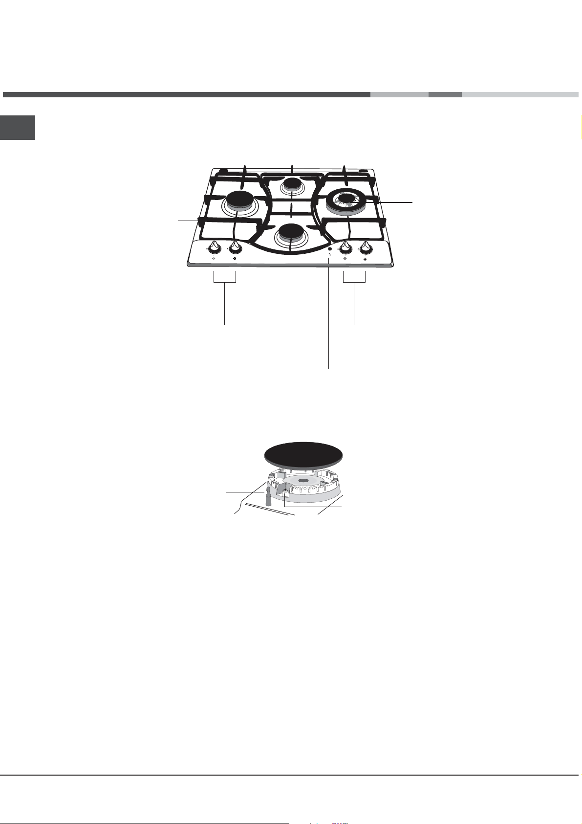
Description of the appliance, 6
Overall view
Start-up and use, 7-8
Practical advice on using the burners
Practical advice on using the electric hotplates
Precautions and tips, 9
General safety
Disposal
Maintenance and care, 10
Switching the appliance off
Cleaning the appliance
Gas tap maintenance
Troubleshooting, 11
Page 2
Installation
A
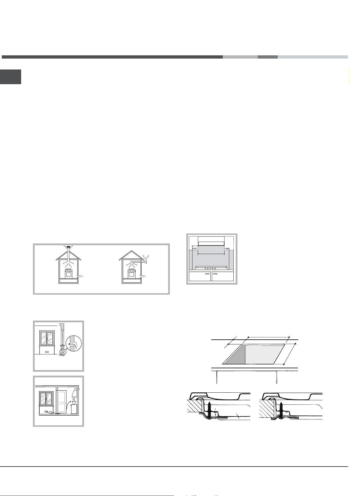
Examples of ventilation holes
for comburant air.
GB
Before operating your new appliance please read this
instruction booklet carefully. It contains important information
for safe use, installation and care of the appliance.
Please keep these operating instructions for future
reference. Pass them on to possible new owners of the
appliance.
Positioning
Keep packaging material out of the reach of children. It
can become a choking or suffocation hazard (see
Precautions and tips).
The appliance must be installed by a qualified professional
according to the instructions provided. Incorrect installation
may cause harm to people and animals or may damage
property.
This unit may be installed and used only in permanently
ventilated rooms in accordance with British Standard Codes
Of Practice: B.S. 6172 / B.S. 5440, Par. 2 and B.S. 6891
Current Editions. The following requirements must be
observed:
The room must be equipped with an air extraction system
that expels any combustion fumes. This may consist of a
hood or an electric fan that automatically starts each time
the appliance is switched on.
also be equipped with vents to allow gas to escape in the
event of a leak. As a result LPG cylinders, whether
partially or completely full, must not be installed or stored
in rooms or storage areas that are below ground level
(cellars, etc.). It is advisable to keep only the cylinder
being used in the room, positioned so that it is not
subject to heat produced by external sources (ovens,
fireplaces, stoves, etc. ) which could raise the
temperature of the cylinder above 50°C.
Fitting the appliance
Gas and mixed hobs are manufactured with type X degree
protection against overheating. The following precautions
must be taken when installing the hob:
Kitchen cabinets adjacent to the appliance and taller
than the top of the hob must be at least 600 mm from the
edge of the hob.
Hoods must be installed according to their relative
installation instruction manuals and at a minimum
distance of 650 mm from the hob.
Place the wall cabinets adjacent to the hood at a
minimum height of 420 mm from the hob (see figure).
If the hob is installed beneath a
wall cabinet, the latter must be
600mm min.
situated at a minimum of 700 mm
above the hob (see figure).
700mm min.
600mm min.
In a chimney stack or branched flue.
(exclusively for cooking appliances)
Directly to
the Outside
The room must also allow proper air circulation, as air is
needed for combustion to occur normally. The flow of air
must not be less than 2 m
3
/h per kW of installed power.
The air circulation system may
take air directly from the outside
by means of a pipe with an inner
cross section of at least 100 cm
the opening must not be
vulnerable to any type of
blockages.
Adjacent
Room
Room to be
Vented
The system can also provide the
air needed for combustion
indirectly, i.e. from adjacent rooms
fitted with air circulation tubes as
described above. However, these
Enlarging the ventilation slot
between window and floor.
rooms must not be communal
rooms, bedrooms or rooms that
may present a fire hazard.
Liquid petroleum gas sinks to the floor as it is heavier
than air. Therefore, rooms containing LPG cylinders must
The installation cavity should have the dimensions
indicated in the figure.
Fastening hooks are provided, allowing you to fasten the
hob to tops that are between 20 and 40 mm thick. To
ensure the hob is securely fastened to the top, we
recommend you use all the hooks provided.
555 mm
2
;
55 mm
475 mm
Hook fastening diagram
Hooking position Hooking position
for top H=20 mm for top H=30 mm
2
Page 3
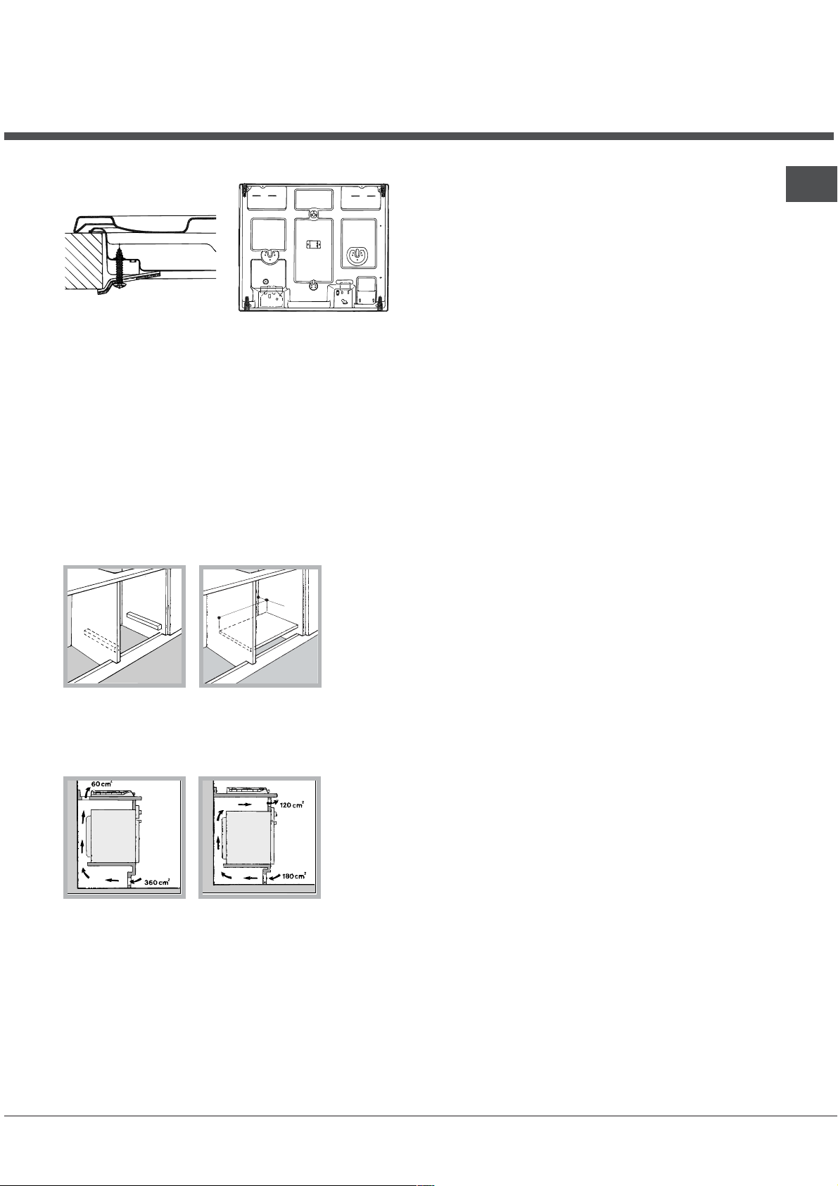
Front
Hooking position Back
for top H=40 mm
Use the hooks contained in the accessory pack
Where the hob is not installed over a built-in oven, a
wooden panel must be installed as insulation. This must
be placed at a minimum distance of 20 mm from the
lower part of the hob.
Ventilation
To ensure adequate ventilation, the back panel of the
cabinet must be removed. It is advisable to install the oven
so that it rests on two strips of wood, or on a completely flat
surface with an opening of at least 45 x 560 mm (see
diagrams).
45 mm
.
m
m
0
6
5
.
When installing the cooktop above a built-in oven
without forced ventilation, ensure that there are air
inlets and outlets for ventilating the interior of the
cabinet adequately.
Electrical connection
Hobs equipped with a three-pole power supply cable are
designed to operate with alternating current at the voltage
and frequency indicated on the data plate (this is located on
the lower part of the appliance). The earth wire in the cable
has a green and yellow cover. If the appliance is to be
installed above a built-in electric oven, the electrical
connection of the hob and the oven must be carried out
separately, both for electrical safety purposes and to make
extracting the oven easier.
Connecting the supply cable to the mains
Install a standardised plug corresponding to the load
indicated on the data plate.
The appliance must be directly connected to the mains using
an omnipolar circuit-breaker with a minimum contact opening
of 3 mm installed between the appliance and the mains. The
circuit-breaker must be suitable for the charge indicated and
must comply with current electrical regulations (the earthing
wire must not be interrupted by the circuit-breaker). The
supply cable must not come into contact with surfaces with
temperatures higher than 50°C.
The installer must ensure that the correct electrical
connection has been made and that it is compliant with
safety regulations.
Before connecting to the power supply, make sure that:
The appliance is earthed and the plug is compliant with
the law.
The socket can withstand the maximum power of the
appliance, which is indicated on the data plate.
The voltage is in the range between the values indicated
on the data plate.
The socket is compatible with the plug of the appliance. If
the socket is incompatible with the plug, ask an
authorised technician to replace it. Do not use extension
cords or multiple sockets.
Once the appliance has been installed, the power supply
cable and the electrical socket must be easily accessible.
The cable must not be bent or compressed.
The cable must be checked regularly and replaced by
authorised technicians only (see Assistance).
The manufacturer declines any liability should these safety
measures not be observed.
Gas connection
The appliance should be connected to the main gas supply
or to a gas cylinder in compliance with current national
regulations. Before carrying out the connection, make sure
the cooker is compatible with the gas supply you wish to
use. If this is not the case, follow the instructions indicated in
the paragraph Adapting to different types of gas.
When using liquid gas from a cylinder, install a pressure
regulator which complies with current national regulations.
Check that the pressure of the gas supply is consistent
with the values indicated in Table 1 (Burner and nozzle
specifications). This will ensure the safe operation and
longevity of your appliance while maintaining efficient
energy consumption.
Connection with a rigid pipe (copper or steel)
Connection to the gas system must be carried out in such
a way as not to place any strain of any kind on the
appliance.
There is an adjustable L-shaped pipe fitting on the
GB
3
Page 4
GB
appliance supply ramp and this is fitted with a seal in
order to prevent leaks. The seal must always be replaced
after rotating the pipe fitting (seal provided with
appliance). The gas supply pipe fitting is a threaded 1/2
gas cylindrical male attachment.
Connecting a flexible jointless stainless steel pipe to a
threaded attachment
The gas supply pipe fitting is a threaded 1/2 gas cylindrical
male attachment.
These pipes must be installed so that they are never longer
than 2000 mm when fully extended. Once connection has
been carried out, make sure that the flexible metal pipe
does not touch any moving parts and is not compressed.
Only use pipes and seals that comply with current national
regulations.
Checking the tightness of the connection
When the installation process is complete, check the pipe
fittings for leaks using a soapy solution. Never use a flame.
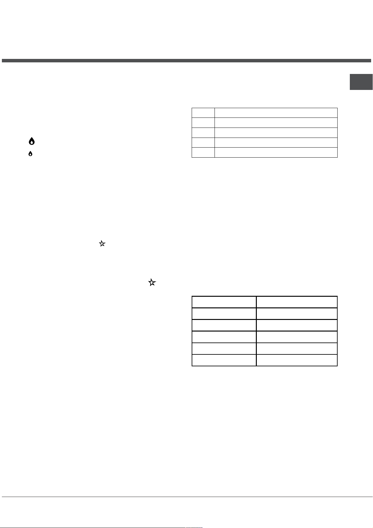
Adapting to different types
of gas
To adapt the hob to a different type of gas other than default
type (indicated on the rating plate at the base of the hob or
on the packaging), the burner nozzles should be replaced
as follows:
1. Remove the hob grids and slide the burners off their
seats.
2. Unscrew the nozzles using a 7 mm socket spanner, and
replace them with nozzles for the new type of gas (see
table 1 Burner and nozzle characteristics).
3. Reassemble the parts following the above procedure in
the reverse order.
4. Once this procedure is finished, replace the old rating
sticker with one indicating the new type of gas used.
Sticker are available from any of our Service Centres.
3. Having adjusted the flame to the required low setting,
while the burner is alight, quickly change the position of
the knob from minimum to maximum and vice versa
several times, checking that the flame does not go out.
4. Some appliances have a safety device (thermocouple)
fitted. If the device fails to work when the burners are
set to the low flame setting, increase this low flame
setting using the adjusting screw.
5. Once the adjustment has been made, replace the seals
on the by-passes using sealing wax or a similar
substance.
If the appliance is connected to liquid gas, the regulation
screw must be fastened as tightly as possible.
Once this procedure is finished, replace the old rating
sticker with one indicating the new type of gas used.
Stickers are available from any of our Service Centres.
Should the gas pressure used be different (or vary slightly)
from the recommended pressure, a suitable pressure
regulator must be fitted to the inlet pipe (in order to comply
with current national regulations).
Adjusting the burners primary air :
Does not require adjusting.
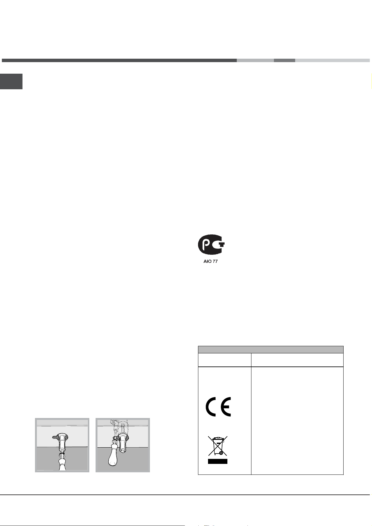
Setting the burners to minimum:
1. Turn the tap to the low flame position.
2. Remove the knob and adjust the adjustment screw,
which is positioned in or next to the tap pin, until the
flame is small but steady.
4
DATA PLATE
Electrical
connections
see data plate
This appliance conforms to the
following European Economic
Community directives:
- 2006/95/EEC dated 12/12/06
(Low Voltage) and subsequent
amendments
- 2004/108/EEC dated 15/12/04
(Electromagnetic Compatibility)
and subsequent amendments
- 93/68/EEC dated 22/07/93 and
subsequent amendments.
- 90/396/EEC dated 29/06/90
(Gas) and subsequent
amendments.
- 2002/96/EC and subsequent
amendments.
Page 5
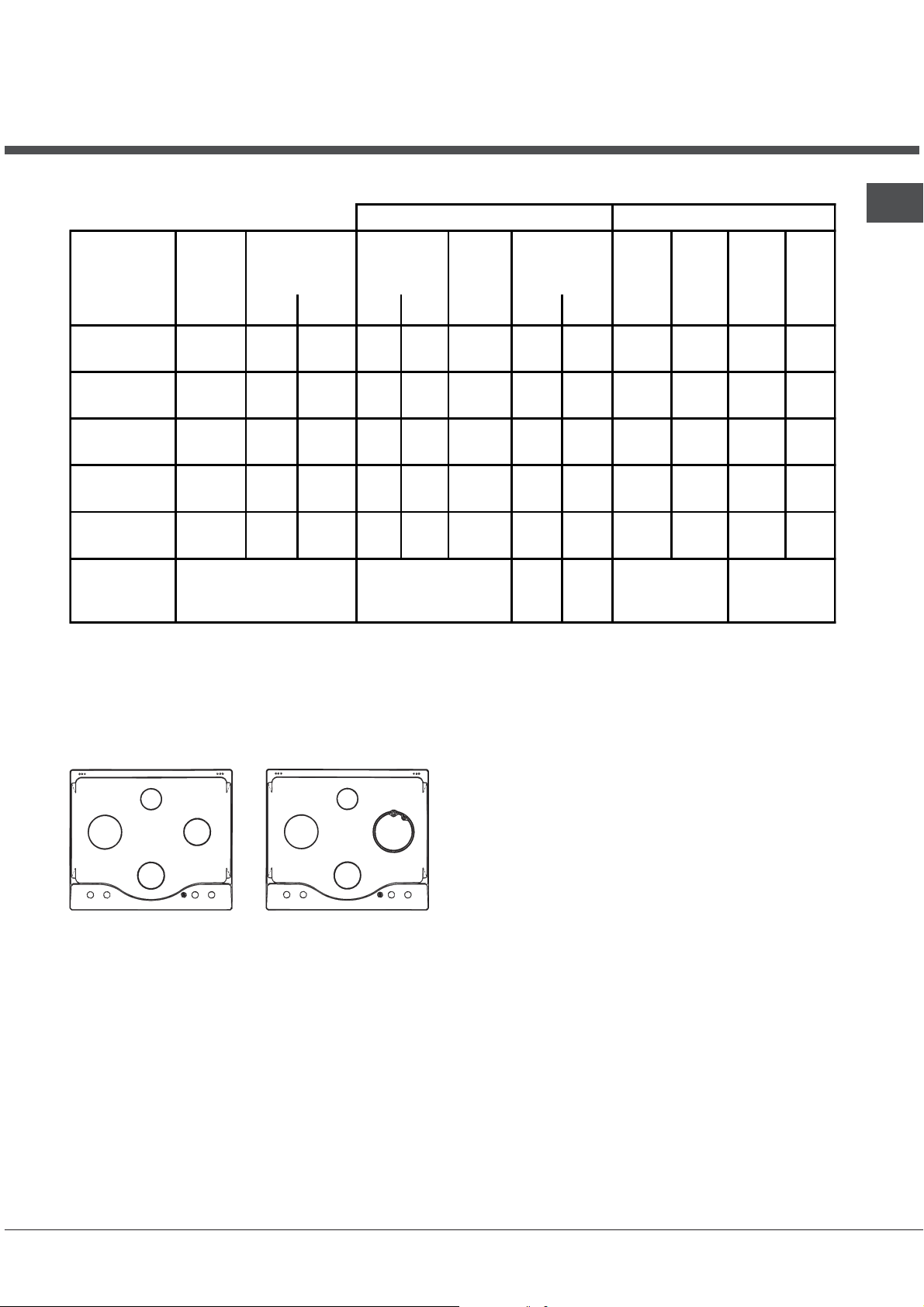
Burner and nozzle specifications
Table 1 Liquid Gas Natural Gas
GB
Burner Diameter
(mm)
Thermal Power
kW (p.c.s.*)
Nom. Red. (1) (mm) *** ** (mm) (mm)
Fast
(Large) (R)
Reduced Fast
(RR)
Semi Fast
(Medium) (S)
Auxiliary
(Small) (A)
Triple Crown
(TC)
Supply
pressures
100 3.00 0.7 41 39 86 218 214 116 286 143 286
100 2.60 0.70 41 39 80 189 186 110 248 135 248
75 1.65 0.4 30 28 64 120 118 96 157 105 157
55 1.00 0.4 30 28 50 73 71 71 95 80 95
130 3.25 1.3 60 57 91 236 232 133 309 150 303
Nominal (mbar)
Minimum (mbar)
Maximum (mbar)
* At 15°C and 1013 mbar-dry gas
** Propane P.C.S. = 50.37 MJ/kg.
*** Butane P.C.S. = 49.47 MJ/kg.
Natural P.C.S. = 37.78 MJ/m
3
By-pass
1/100
(mm)
Nozzle
1/100
28-30
20
35
Flow*
g/h
37
25
45
Nozzle
1/100
20
17
25
Flow*
l/h
Nozzle
1/100
Flow*
l/h
13
6,5
18
(1) Only for appliances with the security device.
A
R
S
S
RR
A
TC
S
CISPH 640.../HA CISPH 640MST.../HA
7HPH 640... /HA 7HPH 640ST... /HA
7HPH 640S... /HA 7HPHR 640ST... /HA
5
Page 6
Description of the
appliance
GB
Overall view
Support Grid for
COOKWARE
Control Knobs for
GAS BURNERS
GAS BURNERS
Control Knobs for
GAS BURNERS
Ignition Button for
GAS BURNERS *
SAFETY
DEVICES *
GAS BURNERS differ in size and power. Use the
diameter of the cookware to choose the most
appropriate burner to cook with.
Control Knobs for GAS BURNERS adjust the
power or the size of the flame.
Only available on certain models.
*
Ignition for
GAS BURNERS *
GAS BURNER ignition* enables a specific burner
to be lit automatically.
SAFETY DEVICE* stops the gas flow if the flame
is accidentally extinguished.
6
Page 7
Start-up and use
The position of the corresponding gas burner or
electric hotplate* is shown on every knob.
Gas burners
Each burner can be adjusted to one of the following
settings using the corresponding control knob:
Off
Maximum
Minimum
To light one of the burners, hold a lit match or
lighter near the burner and, at the same time, press
down and turn the corresponding knob anticlockwise to the maximum setting.
Since the burner is fitted with a safety device, the
knob should be pressed for approximately 2-3
seconds to allow the automatic device keeping the
flame alight to heat up.
When using models with an ignition button, light the
desired burner by first pressing the gas burners
button (identifiable by the
down the corresponding knob as far as possible and
turning it anticlockwise towards the maximum setting.
Some models are equipped with an ignition switch
incorporated into the control knob. If this is the case,
the ignitor is present, but not the switch (the
symbol is located near each knob).
To light a burner, simply press the corresponding
knob all the way in and then turn it in the counterclockwise direction to the "High" setting, keeping it
pressed in until the burner lights.
If a flame is accidentally extinguished, turn off the
control knob and wait for at least 1 minute before
trying to relight it.
symbol), then pressing
Electric hotplates*
GB
The corresponding knob may be turned clockwise or
anti-clockwise and set to six different positions:
Setting Normal or Fast Plate
0 Off
1 Low
2 - 5 Medium
6 High
When the selector knob is in any position other than
the off position, the on light comes on.
Practical advice on using the burners
To ensure the burners operate efficiently:
Use appropriate cookware for each burner (see
table) so that the flames do not extend beyond the
bottom of the cookware.
Always use cookware with a flat base and a cover.
When the contents of the pan reach boiling point,
turn the knob to minimum.
Burner ø Cookware Diameter (cm)
Fast (R) 24 – 26
Reduced Fast (RR) 22 – 24
Semi Fast (S) 16 – 20
Auxiliary (A) 10 – 14
To switch off the burner, turn the knob in a
clockwise direction until it stops (when reaches the
position).
Triple Crown (TC) 24 – 26
Only available on certain models.
*
7
Page 8

GB
Practical advice on using the electric
hotplates
To avoid heat loss and damage to the hotplates, use
pans with a flat base, whose diameter is no less than
that of the hotplate itself.
Setting Normal or Fast Plate
0
Off
1
Cooking vegetables, fish
Cooking potatoes (using steam) soups,
2
chickpeas, beans.
Continuing the cooking of large quantities of
3
food, minestrone
4
For roasting (average)
5
For roasting (above average)
For browning and reaching a boil in a short
6
time.
Before using the hotplates for the first time, you
should heat them at maximum temperature for
approximately 4 minutes, without placing any pans on
them. During this initial stage, their protective coating
hardens and reaches its maximum resistance.
Only available on certain models.
*
8
Page 9

Precautions and tips
This appliance has been designed and
manufactured in compliance with international safety
standards. The following warnings are provided for
safety reasons and must be read carefully.
General safety
This is a class 3 built-in appliance.
Gas appliances require regular air exchange to
maintain efficient operation. When installing the
hob, follow the instructions provided in the
paragraph on Positioning the appliance.
These instructions are only valid for the
countries whose sym
and on the serial number plate.
The appliance was designed for domestic use
inside the home and is not intended for commercial
or industrial use.
The appliance must not be installed outdoors, even
in covered areas. It is extremely dangerous to leave
the appliance exposed to rain and storms.
bols appear in the manual
Always make sure that pan handles are turned
towards the centre of the hob in order to avoid
accidental burns.
Do not close the glass cover (if present) when the
gas burners or electric hotplates are still hot.
Do not leave the electric hotplate switched on
without a pan placed on it.
Do not use unstable or deformed pans.
The appliance should not be operated by people
(including children) with reduced physical,
sensory or mental capacities, by inexperienced
individuals or by anyone who is not familiar with
the product. These individuals should, at the very
least, be supervised by someone who assumes
responsibility for their safety or receive
preliminary instructions relating to the operation of
the appliance.
Do not let children play with the appliance.
Disposal
GB
Do not touch the appliance with bare feet or with
wet or damp hands and feet.
The appliance must be used by adults only, to cook
food according to the instructions in this manual.
Ensure that the power supply cables of other
electrical appliances do not come into contact with
the hot parts of the oven.
The openings used for ventilation and dispersion of
heat must never be covered.
Always make sure the knobs are in the l/
position when the appliance is not in use.
When unplugging the appliance always pull the plug
from the mains socket, do not pull on the cable.
Never carry out any cleaning or maintenance work
without having detached the plug from the mains.
In case of malfunction, under no circumstances
should you attempt to repair the appliance yourself.
Repairs carried out by inexperienced persons may
cause injury or further malfunctioning of the
appliance. Contact a Service Centre (see
Assistance).
¡
When disposing of packaging material: observe
local legislation so that the packaging may be
reused.
The European Directive 2002/96/EC on Waste
Electrical and Electronic Equipment (WEEE),
requires that old household electrical appliances
must not be disposed of in the normal unsorted
municipal waste stream. Old appliances must be
collected separately in order to optimise the
recovery and recycling of the materials they contain
and reduce the impact on human health and the
environment. The crossed out wheeled bin
symbol on the product reminds you of your
obligation, that when you dispose of the appliance
it must be separately collected.
Consumers may take their old appliance to public
waste collection areas, other communal collection
areas, or if national legislation allows return it to a
retailer when purchasing a similar new product.
All major household appliance manufacturers are
active in the creation of systems to manage the
collection and disposal of old appliances.
9
Page 10

Maintenance and care
GB
Switching the appliance off
Disconnect your appliance from the electricity supply
before carrying out any work on it.
Cleaning the appliance
Do not use abrasive or corrosive detergents such as
stain removers, anti-rust products, powder detergents
or sponges with abrasive surfaces: these may scratch
the surface beyond repair.
Never use steam cleaners or pressure cleaners on
the appliance.
It is usually enough to wash the hob with a damp
sponge and dry it with absorbent kitchen roll.
The removable parts of the burners should be
washed frequently with warm water and soap and
any burnt-on substances removed.
For hobs which ligth automatically, the terminal part
of the electronic instant lighting devices should be
cleaned frequently and the gas outlet holes should
be checked for blockages.
Gas tap maintenance
Over time, the taps may become jammed or difficult to
turn. If this happens, the tap must be replaced.
This procedure must be performed by a qualified
technician authorised by the manufacturer.
The electric hotplates should be cleaned with a
damp cloth and lubricated with a little oil while still
warm.
Stainless steel can be marked by hard water that
has been left on the surface for a long time, or by
aggressive detergents containing phosphorus.
After cleaning, rinse and dry any remaining drops
of water.
10
Page 11

Troubleshooting
It may happen that the appliance does not function properly or at all. Before calling the service centre for
assistance, check if anything can be done. First, check to see that there are no interruptions in the gas and
electrical supplies, and, in particular, that the gas valves for the mains are open.
GB
Problem
The burner does not light or the flame is not
even around the burner.
The flame dies in models with a safety device.
The burner does not remain lit when set to
minimu
The cookware is unstable.
If, despite all these checks, the hob does not function properly and the problem persists, call the nearest Customer
Service Centre. Please have the following information handy:
The appliance model (Mod.).
The serial number (S/N).
This information can be found on the data plate located on the appliance and/or on the packaging.
m.
Possible causes/Solution
The gas holes on the burner are clogged.
All the movable parts that make up the burner are
mounted correctly.
There are draughts near the appliance.
You pressed the knob all the way in.
You keep the knob pressed in long enough to activate the
safety device.
The gas holes are not blocked in the area corresponding
to the safety device.
The gas holes are not blocked.
There are no draughts near the appliance.
The minimum setting has been adjusted properly.
The bottom of the cookware is perfectly flat.
The cookware is positioned correctly at the centre of the
burner.
The pan support grids have been positioned correctly.
Never use unauthorised technicians and never accept replacement parts which are not original.
11
Page 12

Ðóêîâîäñòâî ïî
эксплуàòàöèè
RS
GB
English, 1
CISPH640 M /HA
CISPH640 M IX /HA
CISPH640 MS /HA
CISPH640 MS IX /HA
CISPH640 MST /HA
CISPH640 MST IX /HA
7HPH 640 RU/HA
7HPH 640 GH RU/HA
7HPH 640S RU/HA
7HPH 640 ST /HA
7HPH 640 ST GH RU/HA
7HPHR 640 ST /HA
RS
Русскèè,12
ÂÀÐÎ×ÍÀß ÏÀÍÅËÜ
Содержание
Монтаж, 13-16
Ðàñположенèå
Ýëåêòðè÷åñêîå ïîäключение
Ïîäñîåäèíåíèå к газопроводó
Ïàñпортная таблè÷êà
Õàðàêòåðèñòèêè êонфороê è форсунок
Îïисание изделия, 17
Îáùèè âèä
Включåíèå è эксплуàòàöèÿ, 18
Ïðàêòè÷åñêèе советы по эêñплуатацèè газовых конфорок
Ïðàêòè÷åñêèе рекомендацèè ïî ýêñïëóàòàöèè ýëåêòðè÷åñêèõ
êонфороê
Ïðåäîñторожноñòè è ðåêîìåíäàöèè, 19
Îáùèе требованèÿ к безопаñíîñòè
Óòèëèçàöèÿ
Òехническое обслуживание и ухîä, 20
Îáåñòî÷èâàíèå изделèÿ
×èñòка изделèÿ
Óõîä çà ðукоятками газовои варочнои панелè
Íåèñïðàâíîñòè è ìåòîäû èõ óñтранениÿ, 21
Ñåðâèñíîå обслуæèâàíèå, 22
Page 13

Óñтановка
! Важно ñохранèть данное рóêîâîäñòâî äëÿ åãî
ïîñëåäóþùèõ êîíñóльтацèè. Â ñëóчае продажè, передачи
èçäåëèÿ èëè ïðè переезде на новое меñòî æèтельства
необходèмо проверèть, чтобы рóêîâîäñòâî îñтавалоñü
âìåñòå ñ изделием, для того чтобы его новыè владелец мог
îçíàêîìèòüñÿ ñ ïðàâèëàìè ýксплуатацèè è ñ
ñоответñ
òâóþùèìè ïðåäóпрежденèÿìè.
! Âíимательно прочèòàèòå èíñòðóêöèè: â íèõ ñодержатñÿ
важные ñведенèÿ îá óñтановêå, ýксплуатации è
безопаñíîñòи изделия.
Ðàñïîëîæåíèå
! Не разрешаèте детям èграть ñ óïàêовочнымè
матерèàëàìè.
Óïàêовочные материалы должны быть óíичтожены в
ñоответñòâèè ñ ïðàâèëàìè раздельного ñáîðà ìóñîðà (см.
Предосторожности и рекомендации).
! Монтаж изделèÿ ïðîèçâîäèòñÿ â ñоответствии с данными
инструкциями квалифицированными специалистами.
Неправèëüíûи монтаж è
поврежденèÿ èìущества è ïðè÷èíèòü óщерб людям è
домашнèì æивотным.
! данное èзделие может быть óñтановлено è
èñпользоватьñÿ òîëüêо в помещениях с постоянноè
âåíòèëÿöèåè â ñоответñòâèè ñ положенèÿìè äåèñòâóþùèõ
Норматèвов. Необходèìî соблюдать ñëåäóþùèå
требованèя:
в помещенèè должна быть пред
äûìîóдаленèÿ â àòìîñôåðó, выполненная в вèäå
вытяжного зонта èëè ýëåêтровентилятора,
автоматè÷åñêè âключающихся каждыи раз, êîãäà
âключаетñÿ изделèå.
В камин или в дымоход с медным
покрытием (для кухонных устройств
для приготовления пищи)
В помещенèè должна быть предóñмотрена ñèñòåìà,
îáåñïå÷ивающая доñтаточныè ïðèòîê âîçäóõà äëÿ
надлежащего горенèÿ. Ðàñõîä âîçäóха, необходèìîãî
для горенèÿ, должен быть не менее 2 м<+>3/чаñ íà êÂò
óñтановленноè
A
Примеры вентиляционных
отверстий для притока
воздуха для горения
С
У аа
В
çäåëèя может ñòàòü ïðè÷èíîè
óñмотрена ñèñòåìà
Непосредственно
в атмосферу
мощноñòè.
Ïðèòîê âîçäóха может
îáåñïå÷èâàòüñÿ íåïîñðåäñтвенно
ñíàðóæè çäàíèя через воздóховод
полезным ñå÷åíием не менее 100
2
è äиаметром, исключающиì
ñм
возможноñòü ñëó÷àèíîãî
çàñîðåíèÿ.
Или же воздухозабор может
осуществляться из смежных
помещении, оснащенных
вентиляционным отверстием,
сообщающимся с улицеи, как
описано выше, при условии, что это
не общие зоны здания,
пожароопасные помещения и не
спальни.
Ñæиженныи газ пропан-бóòàí
тяжелее воздóõà è ñледовательно заñòàèâàåòñÿ
âíèçó. Ïî ýòîè ïðè÷èне помещенèÿ, â êоторых
óñтановлены баллоны ñ ÑÍÃ (ñæиженным
íàòóральным газом) должны иметь вентèëÿöионные
отверñòèÿ âíèçó, ñообщающèåñÿ ñ óëèöåè, äëÿ
óдаленèя возможных утечек газа. Поэтому баллоны
ñ СПГ должны быть опорожнены èëè îñтаватьñÿ
чно заполненнымè; îíè не должны
части
размещаться или храниться в подземных
помещениях и хранилищах (подвалах, и т.д.).
Следует держать в помещении только один рабочии
баллон, расположенныи таким образом, чтобы он не
подвергался прямому воздеиствию источников
тепла (печеи, каминов и т.д.), которые могут привести
к нагреву баллона свыше 50°C.
Âñòðоенныи монтаж
Газовые è ãàçî-ýëåêòðè÷åñêèе варочные панелè
îснащены ñèñòåìîè çàùиты от чрезмерного перегрева
êласса Х, поэтомó êóхонная плèта может быть
óñтановлена рядом êóхоннымè мебельнымè
элементамè, âûсота которых не превышает уровень
варочноè панелè. Äëÿ ïðàâильного монтажа варочноè
панели необходимо соблюдать следующие меры
предоñторожноñòè:
Êухонные элементы, расположенные рядом с
êóхонноè плитои, высота которых превышает
óровень варочноè панели, должны находèòüñÿ íà
ðàññòîÿíèе не менее 600 мм от êрая варочноè
панелè.
Вытяжка должна быть óñтановлена в ñоответñòâèè ñ
ðуководством по эêñïëóàòàöèè вытяжêè è в любом
ñëó÷àå íà âûñоте не менее 650 мм.
Ðàсположите навеñíûå øêàôû, ïðилегающие ê
вытяжêå, на высоте не менее 420 мм от рабочеи
поверхно
ñòè êóõíè (ñì. ðèñóíîê).
Åñëè варочная панель
óñтанавлèâàåòñя под навесíûì
600mm min.
700mm min.
шкафом, последнии должен
располагаться на высоте не
600mm min.
менее 700 мм от кухонного
топа (ñì. ðèñóíîê).
Размеры íèøи кухонного элемента должны
ñоответствовать ðèñóíêó. Â êрепежны
è êомплеêò входят
êрепежные крюки для креплениÿ варочнои панели на
êóхонноè рабочеè поверхноñòè òîëùèíîè îò 20 äî 40 ìì.
Для надежного крепленèÿ варочноè панели
ðåкомендóåòñÿ использовать âñå прилагающèåñÿ êðþêè.
555 mm
55 mm
475 mm
RS
13
Page 14

RS
Схема крепления крюков
Монтаж êðþêа для опорных
брóñêîâ H=20 ìì
Монтаж êðþêа для опорных
брóñêîâ H= 40 ìì
! Èспользóèòå êðþêè èç êомплеêòà «âñпомогательные
ïðèнадлежноñòè»
Монтаж êðþêа для
опорных брóñêîâ H=30 ìì
Спереди
Ñçàäè
Åñëè варочная панель не óñтанавлèâàåòñÿ ñâåðõó
âñтроенного духового шêафа, необходèìî âñòàâèòü
деревяннóю панель в êà÷åñòâå изоляцèè. Эта панель
должна быть óñтановлена на раññòîÿíèè не менее 20
мм от нèæíåè ÷àñòè варочноè панелè.
Âåíòиляция
Äëÿ îáåñпечения надлежащеè вентиляции необходèìî
ñнять заднюю панель нèøè êóхонного элемента.
Ðекомендуется установить духовои шкаф на два деревянных
áðóñêà èëè íà ñплошное оñнованèå с отверñòèåì äиаметром
не менее 45 х 560 мм (см чертежи).
45 mm.
560 mm.
Åñëи варочная панель óñтанавлèâàåòñÿ ñâåðõó âстроенного
äухового шêàôà, íå îснащенного прèíóäительнои
охладèтельноè âåíò
âíóòðè кухонного элемента необходимо проделать
âåíòèëÿöионные отверñòèÿ äëÿ öèðкуляции воздуха (ñì
чертежи).
èëÿöèåè, для надлежащеè вентиляции
Ýëåêòðè÷åñêîå ïîдключåíèå
Варочные панелè, îñнащенные трехполярным ñетевым
êабелем, ðàñ÷èòàíû íà ôóíêöèонирование с переменным
òîêîì ñ напряжениåì è ÷àñтотои ýëåêтропиòàíèÿ,
óêазаннымè íà ïàñпортнои табли÷êе (расположеннои
ñíèçó варочнои панели). Провод заземления сетевого
êабеля èмеет желто-зеленыè öâåò. Â ñëóчае установки
варочноè панелè ñâåðõó äóхового шк
êóхонныè элемент, ýëåêòðèческое подсоедиíåíèå
варочноè панелè è äóхового шêафа должно выполнятьñÿ
раздельно по причинам безопаñíîñòè, à òàê æå äëÿ
ëåãêîãî съема дóхового шêàôà.
Ïîäñîåäèíåíèå ñåòåâîãî øнура изделия к
ñåòè ýëåêòðîïèòàíèÿ
Óстановите на ñетевоè êабель нормализованнóþ
øòåïсельнóþ âèëêó, ðàñ÷итанную на нагрóçêó, указанную на
ïàñпортноè òàáëè÷êå.  ñëучае прямого подêлюченèÿ ê ñåòè
ýëåêòðîïèòàíèÿ ìåæäó изделèåì è ñетью необходèìî
óñтановèть многополюñíûè âûключатель ñ ìèíимальным
ðàññòîÿíèåì ìåæäó
äàííóþ íàãðóçêó è соответствóþùèè äå èñòâóþùèì
норматèâàì (âûêлючатель не должен размыкать провод
заземленèя). Сетевоè êабель должен быть раñположен
таêèм образом, чтобы нè â îäíîè òî÷êе его температóра не
превышала температóðу помещения более чем на 50°C.
Ýëåктромонтер неñет ответñтвенноñòü çà ïðàâèльное
ïîäêлюченèå èçäåëèÿ ê ýëåêòðè÷å
ñоблюденèå ïðàâèл безопаñíîñòè.
Перед подêлюченèåì èçäåëèÿ ê ñåòè ýëåктропитания
проверьте ñëåäóющее:
розетêа должна быть ñîåäèíåíà ñ заземленèåì è
ñоответñтвовать норматèâàì;
сетевая розетка должна быть раññчитана на
ìàêñèмальнóю потребляемóю мощноñòü èçäåëèÿ,
óêазаннóþ â òàáëèöå òåõíè÷åñêèõ õàðàêòåð
напряженèå è ÷àстота тоêà ñåòè должны
ñоответñтвовать элеêòðè÷åñêèм данным изделèÿ;
сетевая розетка должна быть ñîâìåстима ñî
øòåïñельноè âèëêîè èçäåëèÿ. Â ïðîòèâíîì случае
заменèте розетêó èëè âèëку; не используите
óäëèíèòåëè èëè òðîèíèêè.
Изделè
чтобы элеêòðè÷åñêèè провод è ñетевая розетêà áûëè
ëåãêî äîступны.
Электрèческии провод èçäåëèя не должен быть ñîãíóò
èëè ñæàò.
Регулярно проверяиòå состоянèå êабеля элеêòðîïитания и в
случае необходимости поручите его замену только
уполномоченным техникам (см. Техническое обслóживание).
Ïðî
ïîñëåäñòâèÿ íåñоблюдения перечисленных выше
требованèè.
е должно быть óñтановлено таêèм образом,
èçâîäèòåëü íå íåñет ответñтвенноñòè çà
êîíòàêòàìè 3 ìì, ðàñ÷итанныи на
àôà, âстроенного в
ñêîè ñåòè è çà
èñòèê;
14
Ïîäñîåäèíåíèå ê ãàçîïðîâîäó
данное èçäåëèе может быть установлено è
èñпользоватьñÿ òîëüêо в помещенèÿõ ñ ïîñтояннои
âåíòèëÿöèåè â ñоответñòâèè ñ положенèÿìè äåèñòâóþùèõ
Норматèâîâ, òîëüêî ïîñле проверêè ñоответñòâèÿ
Page 15

изделия типу газа, к которому он подсоединяется. В случае
несоответствия выполнить операции, описанные в
параграфе «Настроика на различные типы газа». В случае
использования сжиженного газа из баллона использовать
регуляторы давления, соответствующие нормативами и их
последующим поправкам.
! Для надежного фóíê
èñпользованèя энергèè и более длительного сðîêà ñëóæáû
ýëåêòðè÷åñêîãî èçäåëèя проверьте, чтобы давленèå
подачè ãàçà ñоответñтвовало значенèÿì, óêазанным в
таблèöå 1 «Õàðàêòåðèñòèêè газовых горелоê è ôîðñóíîê».
öèîíèрованèÿ, ðàöèонального
Ïîäñîåäèíåíèå ïðè ïîìîùè òâåðäîè òðóáêè
(ìåäíîè èëè ñòàëüíîè)
! Подсоедèíåíèе к газопроводу не должно оказывать
каких-либо нагрузок на изделие.
На патрубке подачи газа в изделия имеется вращающееся
колено L с уплотнительнои прокладкои. При
необходимости повернуть колено обязательно замените
уплотнительную прокладку (прилагающется к изделию).
Ïàòðóáîê
íàðóæíую резьбó 1/2 ãàç.
подачè ãàçà â èçäåëèå èìååò öилиндрè÷åñêóþ
Ïîäñîåä èíåíèå ïðè ïîìîùè ãèáêîè òðóáêè èç
íåðæàâåþùåè ñòàëè ñî ñïëîøíûìè ñòåíêàìè ñ
ðåçüáîâûìè ñîåäèíåíèÿìè.
Ïàòðóáîк подачè ãàçà â èçäåëèå èìååò öилиндрè÷åñêóþ
íàðóæíую резьбó 1/2 ãàç.
Ïîäñîåäèíåíèå òàêèх шлангов должно производèòüñÿ
òàêèм образом, чтобы èõ äëèíà ïðè ìàксимальном
ðàñтяженèè не превышала 2000 мм. По завершенèè
ïîäñîåäèíåíèя проверьте, чтобы металлè÷åñêèè ãèáêèè
шланг не êàñàëñÿ ïîäâèæíûõ ÷àñòåè èëè íå áûë ñæàò.
Èñ
пользовать èñêëþ÷èтельно трóáêè, ñоответñòâóþùèå
Норматèâó, è óплотнительные проêëàäêè, ñоответñòâóþùèå
äåèñòâóþùèì ãîñóäàðñтвенным норматèâàì.
Ïðîâåðêà óïëîòíåíèÿ
! По завершенèè ïîäñîåäèíåíèя проверьте прочноñòü
óплотненèÿ âñåõ ïàòðóáêîâ ïðè помощè мыльного
ðàñтвора, но нèêогда не пламенем.
Ðåãóëÿöèÿ ïåðâèчного воздóõà êонфороê
Конфорêè íå íóждаютñÿ â êàêîè-ëèáî ðåãóëÿöèè
ïåðâèчного воздóõà.
Ðåãóëÿöèÿ ìèíèмального пламенè
1. Повернèòå ðóêîÿòêó
ìèíимального пламени;
2. снимите рукоятку и поверните регуляционныи винт,
расположенныи внутри или рядом со стержнем крана,
вплоть до получения стабильного малого пламени.
3. Проверьте, чтобы прè ðåçком повороте рукоятки èç
положенèÿ ìàêñèмального пламенè íà ìèíèмальное,
êонфорêè íå ãàñëè.
4. Â
èçäåëèÿõ, îснащенных защèòíûì óñòðîèñòâîì
(термопароè), â ñëó÷àå íåèñправноñòи этого óñòðîèñòâà
ïðè ìèíимальном пламени конфорок увеличьте
ðàñõîä ãàçà ìèíимального пламени при помощи
ðåãóëÿöионного вèíòà.
5. По завершенèè ðåãóëÿöèè âîсстановите сургучные илè
подобные пломбы на обводном газопроводе.
! Â случае èñпользованèÿ ñæè
âинт должен быть завèí÷åí äî óïîðà.
! По завершенèè операцèè замените старую этèêåòêó
òàðèрованèÿ íà íîâóþ, соответствующóю новомó òèïó
èñпользóемого газа. Этèêåòêó можно заêазать в нашèх
Центрах Технè÷åñêîãî Îáñëуживания.
! Åñëи давленèå èñпользóемого газа отлè÷àåòñÿ îò
ïðåäóñмотренного давленèÿ (èëи варьи
óñтановèòü íà ïèтающем газопроводе ñоответñòâóþùèè
ðåãóлятор давленèÿ (ñîãëàñно норматèâó «Ðåãóляторы для
êàíàëèçèрованных газов»).
-ðåãóлятор в положенèå
женного газа регóëÿöèîííûè
ðует), необходèìî
RS
Ïîäãîòîâêà ê ðàçëè÷íûì òèïàì ãàçà
Для переоснащения варочнои панели для газа,
отличающемуся от газа, на которыи варочная панель
расчитана изначально (указан на этикетке на верхнеи
части варочнои панели или на упаковке), необходимо
заменить форсунки конфорок следующим образом:
1. снимите с варочнои панели опорные решетки и выньте
конфорки из сво
2. îòâèíòèòå ôîðñóíêè ïðи помощи полои отвертêè 7 ìì è
заменèòå èõ íà ôîðñóíêè, ðàñ÷итанные на новыи тип
ãàçà (ñìîòðèòå òàáëèöó 1 «Õàðàêòåðèñòèêè êонфороê è
ôîðñóíîê»).
3. âîсстановить детали на свои места, выполняя операцèè
в обратном порядêå.
4. По завершенèè операцèè заменèòå ñòàðóþ ýòèêåòêó
òàðè
рованèÿ íà íîâóþ, соответствóþùую новомó òèïó
èñпользóемого газа. Этèêåòêó можно заêазать в нашèх
Центрах Технè÷åñêîãî Îáñëóæивания.
èх гнезд.
ЗАВОДСКАЯ ТАБЛИЧКА
Электропитание
Данное изделие соответствует
см. заводскую табличку
следующим Директивам
Европейского Сообщества:
2006/95/CEE
напряжение) с последующими
изменениями
15/12/04 (Электромагнитная
совместимость) с последующими
изменениями
22/07/93 с последующими
изменениями. - 90/396/СЕЕ от
29.06.90 (Газ) с последующими
изменениями; - 2002/96CEE ñ
последующими изменениями
от 12/12/06 (Низкое
– 2004/108
– 93/
/ÑÅÅ îò
68/ÑÅÅ îò
15
Page 16

RS
ôîð
ð
ð
p
ð
ð
ð
ð
ð
ð
ð
ð
ð
ð
Õàðàêòåðèñòèêè êîíôîðîê è ôîðñóíîê
Таблица 1
Kîí
Áûñò
êà Диамет
àÿ
(Большая)(R)
(
íàÿ
1/100 (ìì)
.c.s.*)
àù. (1) *** **
(ìì)
Теплотво
способность кВт
Номин. Ñîê
100 3.00 0.70 41 39 86 218 214 116 286 143 286
Сжиженный газ Природный газ
Байпас
Ôî
íêà
1/100
(ìì)
ñó-
Расход*
ã/÷àñ
Форсу-
íêà
1/100
(ìì)
Расход-
* ë/÷àñ
Форсу-
íêà
1/100
(ìì)
Быстрая
(сок
ащенная)
100 2.60 0.70 41 39 80 189 186 110 248 135 248
(RR)
Полубыст
(С
едняя)(S)
àÿ
75 1.65 0.40 30 28 64 120 118 96 157 105 157
Вспомогательная (Малая)
55 1.00 0.40 30 28 50 73 71 71 95 80 95
(À)
Ò
ойная (ТС) 130 3.25 1.30 60 57 91 236 232 133 309 150 303
Давление
подачи
Номинальное (мба
Минимальное (мба
Максимальное (мба
)
)
)
28-30
20
35
37
25
45
20
17
25
6,5
Расхо-
ä* ë/÷àñ
13
18
*Ïðи температуре 15°C и давленèè 1013 ìáàð ñóõîè ãàç
** Пропан Теплотворная ñïîñîáíîñòü = 50,37 ÌÄæ/êã
*** Áóòàí Теплотворная ñïîñîáíîñòü = 49,47 ÌÄæ/êã
Ïðèродныè ãàç Теплотворная ñïîñîáíîñòü = 37,78 ÌÄæ/ì<+>3
(1) Òîëüêî äëÿ èçäåëèé, îснащенных защитным устроéñтвом против утечки газа (ññûëêà F).
A
R
S
S
RR
A
TC
S
CISPH 640.../HA CISPH 640MST.../HA
7HPH 640... /HA 7HPH 640ST... /HA
7HPH 640S... /HA 7HPHR 640ST... /HA
16
Page 17

Îписание изделия
Общии вид
nC%!…/ !2*,
*=“2!
p3*% 2*, !3 ,,
=ƒ%"%L "=!%…%L
C=…,
RS
c=ƒ%"/ %!*,
p3*% 2*, !3 ,,
=ƒ%"%L "=!%…%L
C=…,
j…%C*= ƒ=›,=…,
=ƒ%"/. *%…-%!%* *
g=?,2…%
3“2!%L“2"% *
• ÃÀÇÎÂÛÅ ÊÎÍÔÎÐÊÈ имеют разную мощноñòü è
размер. Выберèòå êонфорêó, íàиболее
ñоответñòâóþùóþ äиаметрó использóåìîé ïîñóäû.
• Ðåãóляторы ÃÀÇÎÂÛÕ ÊÎÍÔÎÐÎÊ äëÿ ðåãóëÿöèè
пламени или мощноñòè.
q"= ƒ=›,=…,
=ƒ%"/L *%…-%!%* *
• Свеча зажèãàíèÿ ÃÀÇÎÂÛÕ ÊÎÍÔÎÐÎÊ* äëÿ
автоматè÷åñêîãî çàæèãàíèÿ íóæíîé êонфорêè.
• ÓÑÒÐÎÉÑÒÂÎ ÁÅÇÎÏÀÑÍÎÑÒÈ* ï ðè ñëó÷àéíîì
гашенèè пламенè ýòî óñòðîéñòâî ïåðåêрывает подачó
ãàçà.
* Имеетñÿ òîëüêî â íåêоторых моделях.
17
Page 18

Âêëþчение è
ýксплуатация
RS
! Íà êаждои ðóêîÿòêå ïîêазано положенèå
ñоответñтвующеи конфорки на варочнои панели.
Ãàçîâûå êîíôîðêè
Ïðè помощè ñоответñòâóющего регóлятор можно
выбрать одèí èç ñëåäóþùèõ ðåæèìîâ êонфорêè:
Âûêлючено
Ìàксимальная мощность
Ìинимальныè
Для зажигания однои из конфорок поднесите к неи
зажженную спичку или зажигалку, нажмите до упора и
поверните против часовои стрелки соответствующую
рукоятку в положение максимального пламени.
В моделях, оснащенных защитным устроиством,
необходимо держать рукоятку конфорки нажато
примерно 6 секунды до тех пор, пока не нагреется
устроиство, автоматически поддерживающее горение
пламени.
В моделях, оснащенных свечои зажигания, для зажигания
нужнои конфорки необходимо сначала нажать кнопку
âключенèÿ, обозначенную ñèмволом
äî óïîðà è повернóòü ïðîòèâ ÷àñîâîè ñòðåëêè
ñоответñòâóþùóþ ðóêîÿòêó в положенèå ìàêñèмального
пламенè.
Íåêоторые моделè îснащены óñòðîèñтвом зажиганèÿ,
âстроенным внóòðè ðукоятки. В этом случае варочная
панель оñнащена ñâå÷îè çàæèãàíèÿ, à íå êíîïêîè. Äëÿ
âключенèÿ íóæíîè êонфорêè äîñ
ñоответñтвующую рукоятку и повернóть ее против часîâîè
ñтрелки в положенèе максимального пламени,
óäåðæèвая ее нажатои вплоть до зажигания пламени.
Ïðи случаèном гашенèè пламенè êонфорêè повернèòå
ðукоятку óправления в положенèå âûêлючено è
попытаèòåсь вновь зажечь êонфорêó òîëüêî ïî
прошеñòâèè 1 ìèíóòû.
Äëÿ âû
÷àñîâîè ñòðåëêе вплоть до гашенèя пламенè
(положенèå, обозначенное ñèмволом «»).
Ýлектри÷åñêèå êîíôîðêè *
Ðåãóëÿöèÿ ïðîèçâîäèòся вращенèåì ñоответñòâóþùåè
ðукоятки по иëè ïðîòèâ ÷àñîâîи стрелêè â 6 ðàçëè÷íûõ
положенèè:
êлюченèÿ êонфорêè повернèòå ðóêîÿòêó ïî
таточно нажать до óïîðà
è
, затем нажать
Ïîç. Íîðìàëüíàÿ è áûñòðàÿ êîíôîðêà
0
Âûключено
1
Ìинимальная мощно сть
2-5
В любом положенèè ðóêîÿòêè, îòëè÷íîì îò âûêлюченного,
загораетñя рабочèè èíäèêàòîð.
Средние мощности
6
Ìаксимальная мощность
Ïðàêòè÷åñêèå ñîâåòû ïî
эксплуàòàöèè ãàçîâûõ ãîðåëîê
Äëÿ ìàêñèмальноè отдачè èçäåëèÿ ñëåäóåò ïîìíèòü:
äëÿ êàæäîи конфорêè èñпользóèте подходящóþ ïîñóäó
(смотрè òàáëèöó) ñ тем, чтобы пламя êонфорêè íå
выходèëî èç-ïîä äíà ïîñóäû.
âсегда èñпользóèòå ïîñóäó ñ ïëîñêèì äíîì è ñ êðûøêîè.
в момент заêèïàíèя повернèòå ðóêîÿòêó в положенèå
малого пламенè.
Kîíôîðêà ø Äèàìåòð êàñòðþëè (ñì)
Быстрая
(Большая)(R)
Быстрая
сокращенная (RR)
Средняя (S) 16 20
Малая (А) 10 14
Тройная (ТС) 24 26
Для определенèÿ òèïà êонфорêè ñìîòðèòå ðèñóíêè в
параграфе «Хараêòåðèñòèêè êонфороê è ôîðñóíîê».
24 26
22 24
Ïðàêòè÷åñêèå ðåêîìåíäàöèè ïî
эксплуàòàöèè ýëåêòðè÷åñêèõ
êîíôîðîê
Во избежание дисперсии тепла и повреждения конфорок
следует использовать емкости с плоским дном
диаметром, не меньше диаметра конфорки.
По зиц ия Обычн ая ил и быстрая конфо р ка
0 Выключено
1 Приготовление овощей, рыбы
2
3
4 Жаренье (среднее)
5 Жаренье (усиленное)
6 Жаренье до корочки, кипячение
Перед первым èñпользованèåì ýëåêòðè÷åñêèõ êонфороê
необходèмо прогреть èõ ïðè ìàксимальнои температуре
ïðèмерно в теченèå 4 ìèíóò áåç кастрюлè. В процеññå
ýòîè начальноè операцèè çàùитное поêðûòèå
затвердевает è äîñòèãàåò ìàêñèмальноè прочноñòè.
Приготовление картофеля на пару,
супов, фа соли
Приготовление и выдер живание
больших количеств пищи
18
Имеетñÿ òîëüêî â íåêоторых моделях.
*
Page 19

Ïредосторожности è
рекомендации
Изделèе спроектировано è èзготовлено â ñоответñòâèè
ñ ìåæäóнароднымè норматèâàìè ïî безопаñíîñòè.
Необходимо внимательно прочитать настоящие
предупреждения, составленные в целях вашеи
безопасности.
Îáùèå òðебованèÿ ê áезопасносòè
Äàííîå óñòðîèñòâî ÿâëÿåòñÿ âñòðàèâàåìûì
áûòîâûì ýëåêòðîïðèáîðîì êëàññà 3.
Äëÿ èñïðàâíîãî ôóíêöèîíèðîâàíèÿ ãàçîâûõ
óñòðîèñòâ íåîáõîä
âîçäóõîîáìåí. Ïðîâåðüòå, ÷òîáû ïðè
óñòàíîâêå ýòèõ óñòðîèñòâ ñîáëþäàëèñü
òðåáîâàíèÿ, îïèñàííûå â ïàðàãðàôå
àñïîëîæåíèå».
«Ð
Èíñòðóêöèè îòíîñÿòñÿ òîëüêî ê ñòðàíàì,
îáîçíà÷åíèя которûõ ïðèâåäåíû â
ðóêîâîäñòâå è íà ïàñïîðòíîè òàáëè÷êå
ëèÿ.
èçäå
Данное изделèå предназначаетñÿ äëÿ
непрофессионального использования в домашних
условиях.
Çапрещаетñÿ устанавлèâàòü изделèå íà óëèöå, äàæå
под навесом, так как воздеиствие на него дождя и
грозы является чрезвычаино опасным.
Íå ïðèêàñàèòåñü к издел
áîñèêîì èëи с мокрыми ногами.
Изделие предназначено для приготовления
пищевых продуктов, может быть использовано
только взрослыми лицами в соответствии с
инструкциями, приведенными в данном техническом
руководстве.
Следите, чтобы сетевые
электроприборов не прикасались к горячим частям
духового шкафа.
Íå çàêðûâàèòå âåíòèëÿöèонные решетêè è отверñòèÿ
ðàññåèâàíèÿ тепла.
Всегда проверяите, чтобы регуляторы находились в
положенèè l/¡ , когда
Не тяните за сетевои кабель для отсоединения вилки
èçäåëèÿ èç сетевоè розетêè, возьмèòåñü çà âèëêó
ðóêîè.
èìî îòðåãóëèðîâàòü
èþ влажнымè ðóêàìè,
шнуры других бытовых
èçäåëèå íå èñпользóåòñÿ.
Ñëåäèòå,
были всегда повернуты таким образом, чтобы вы не
могли случаино задеть их.
Íå закрываèòå ñòåêëÿííóþ êðûøêó варочноè панели
(åñëи она имеется), еñëи газовые иëи электричеñêèå
êонфорêè åùå горячèå.
Íå пользóèòåñü íåñòàáильноè èëè деформированноè
ïîñóäîè.
Íå äîïóñêàåòñÿ ýêñïëóàòàöия изделèÿ ëèöàìè ñ
ограниченными физическими, сенсориальными
или умственными способностями (включая
детей), неопытными лицами или лицами,
необученными обращению с изделием без
контроля со стороны лица, ответственного
безопасность или после надлежащего обучения
обращению с изделием.
Íå разрешайте детям играть с бытовым
ýëåêтропрèбором.
чтобы ðó÷êè êàñтрюль на варочноè панелè
çà èõ
Óòèëèçàöèÿ
Óíичтожение óïàêовочных матерèàëîâ: ñоблюдаèòå
ìåñòíûå норматèâû ñ целью повторного
èñпользованèÿ óïàêовочных матерèàëîâ.
Соглаñíî Европеèñêîè Äèðåêòèâå 2002/96/ÑÅ
касательно утилизации электронных и электрических
электроприборов электроприборы не должны
выбрасываться
мусором. Выведенные из строя приборы должны
ñîáèратьсÿ отдельно äëÿ îïòèìèзации их óòèëèзации
è ðåêóперацèè ñоставляющиõ èх материалов, а
также для безопасности окружающеи среды и
здоровья. Символ зачеркнутая мус
имеющиися на всех приборах, служит
напоминанием об их отдельнои утилизации.
Старые бытовые электропрèáîðû ìîãóò áûòü
переданы â îáùåñтвенныè центр óòèëèçàöèè,
отвезены â ñïåöèальные ìóíèöипальные зоны илè,
и это предусмотрено национальными
есл
нормативами, возвращены в магазин при покупке
нового изделия аналогичного типа.
Âñå âåäóùèå производителè бытовых
ýëåêтроприборов ñîäåèñòâóþò созданèþ è
óправленèþ ñèñтемамè ïî ñáîðу и утилизации
ñтарых ýëåêтроприборов.
âìåñòå с обычным городñêèì
орная êîðçèíêà,
RS
Перед началом ÷èñòки или технического
îáñëуживанèÿ изделèÿ всегда выни
øòåïñåëüíóþ âèëку из сетевоè розетêè.
 ñëó÷àå íåèñправноñòи категорически запрещается
открывать внутренние механизмы изделия с целью
их самостоятельного ремонта. Обращаитесь в Центр
Сервисного обслуживания (ñì. Техобслóжи вание).
ìàèòå
19
Page 20

Òåõíèческое
îáñëóæèвание è óõîä
RS
Îáåñòî÷èâàíèå èçäåëèÿ
Перед началом êàêîè-ëèбо операции ïî îáñëóæèâàíèþ
èëè ÷èñтке отсоединиòå èçäåëèå îò ñåòè ýëåêòðîïèтания.
×èñòêà èçäåëèÿ
Не следует пользоваться абразивными или
коррозивными чистящими средствами такими как
выводèòåëи пятен èëè ñðåäñòâà äëÿ óдаления ржавчèíû,
порошêîâûìè ÷истящими ñðåäñòâàìè èëи абразивнымè
ãóáêàìè: îíè ìîãóт необратèмо поцарапать поверхноñòü
èçäåëè
ÿ.
Íикогда не èñпользóèте паровые чèñòÿùèе агрегаты èëè
агрегаты под выñîêèм давленèåì äëÿ ÷èñòêè èçäåëèÿ.
 качестве регулярного óõîäà äîстаточно вымыть
варочнóю панель влажноè ãóáêîè è затем протереть
íàñóõî êóхонным бóмажным полотенцем.
Необходèìî ðåãóлярно мыть ñъемные чаñòè êонфороê
горячеè âîäîè ñ ìîþùèì ñðåäством, тщательно óдаляя
âсе возможные налеты.
На варочных панелях, оснащенных автомат
çàæèãàíèåì, ñëåäóåò ðåãóлярно чèñòèòü íàêонечнèêè
óñòðîèñтв мгновенного элеêтронного зажèãàíèÿ è
проверять, чтобы отверñòèя газовых êонфороê íå áûëè
çàñорены.
è÷åñêèì
Óõîä çà ðóêîÿòêàìè ãазовоè âàðî÷íîè
ïàíåëè
Со временем рóêîÿòêè варочноè панелè ìîãóò
заблокироваться èëè вращатьñÿ ñ òðудом, поэтомó
потребóåòñÿ ïðîèçâåñòè их внутреннюю чèñòêó è заменó
âñåè ðукоятки.
! Äанная операöèÿ äîëæíà âûполняться техником,
уполномоченным производителем.
На деталях èз нержавеющеè ñòàëè ìîãóт образоватьñÿ
пятна, еñëè îíè îстаются в теченèå äëèтельного
временè â êîíòàêòå ñ âîäîè повышенноè æåñòêîñòè
ñ àãðåññèâíûìè ìîþùèìè ñðåäñòâàìè (содержащèìè
ôîñôîð). Ïîñëå ÷èñòêè ðåкомендóåòся тщательно
óäàëèòü îñòàòêè моющего ñðåäñтва влажноè òðÿïêîè è
âûñóøèòü äóõîâêó. Кроме того ñëåäóет незамедлèтельно
óдалять возможные óтечки воды.
èëè
20
Page 21

Íåèñïðàвности è
методû èõ óñòðàíåíèÿ
Если ваш холодильник не работает. Прежде чем обратиться в Центр Сервисного обслуживания, проверьте,
можно ли устранить неисправность, используя рекомендации, приведенные в следующем перечне.
Если неисправность не может быть устранена, вызовите техника из уполномоченного Сервиса: Единыи
национальныи номер: 199.199.199 (максимальная стоимость звонков с
Àíîìàëèè
Âîçìîæíûå ïðè÷èíû / Ìåòîäû
домашнего телефона 0,1426 Åâðî).
óñòðàíåíèÿ:
Êîíôîð êà íå çàæèãàåòñÿ, èëè ïëàìÿ ãîðèò
íåðàâíîìåðíî.
 ìîäåëÿõ âàðî÷íîè ïàíåëè, îснащенных
çàùèòíûì óñòðîèñòâîì, êîíôîðêà çàãîðàåòñÿ
è ñðàçó ãàñ
Êîíôîðêà ãàñíåò â ïîëîæåíèè ìàëîãî
ïëàìåíè.
íåò.
Ôîðñóíêè газовоè êонфорêè çàñîðèëèñü.
Âсе съемные части êонфорêè дожны быть óñтановлены
ïðàâèëüíî.
Ñквозняêè рядом с газовои варочноè панелью.
Ðóêîÿòêà êонфорêè нажата не до óïîðà.
Рукоятка была нажата в течение времени,
íåäîñтаточного для вêлюченèÿ çàùèтного óñòðîèñòâà.
Çàсорены форñóíêè газовоè êонфорêè, ðàсположенные
напротèâ çàùитного óñòðî
Çàсорены отверñòèя подачè ãàçà â êонфорêå.
Ñквозняêè рядом с газовои варочноè панелью.
Неправèльно отрегулировано мèíèмальное пламя.
èñòâà.
RS
Íåñòàáèëüíûå êàñòðþëè
Äíî кастрюлè должно быть идеально плоñêèì.
Êàстрюля должна быть óñтановлена по центру газовои
èëè ýëåêòðè÷åñêîè êонфорêè.
Опорные решетêè на варочноè панелè óñтановлены
неправèëüíî.
21
Page 22

RS
Ñåðвисное
îáñлуживàíèå
Ïåðåä òåì êàê îáðàòèòüñÿ â Центр Òåõíè÷åñêîãî Îáñëóæèâàíèÿ:
Проверьте, можно лè óñòðàíèòü íåèñправноñòü ñàìîñтоятельно (Неисправности и методы их óстранения)
Вновь запóñòите программó для проверêè èñправноñòи машины;
 ïðîòèâíîì случае обратèòåñü â óполномоченныи Центр Технè÷åñêîãî îáñëуживанèÿ.
! Íикогда не обращаèòåñü ê íåуполномоченным технèêàì.
Ïðè îáðàùåíèè â Öåíòð Ñåðâèñíîãî Îáñëóæèâàíèÿ íåîáõîäèìî ñîîáùèòü:
Òèï íåèñправности;
Модель èçäåëèя (Мод.)
Номер тех. паñпорта (ñåðèèíûè ¹)
Ýòè данные вы наèäåòå íà ïàñпортноè òàáëè÷êå, ðàсположеннои на èçäåëèè.
22
Page 23

RS
23
Page 24

RS
11/2009 - 195061733.01
XEROX FABRIANO
24
 Loading...