

Hotpoint 5200 Installation & Setup Manual

Installation & Setup Guide
HotPoint
HotPoint 5000 Access Point
FWC2050 WLAN Controller
Manual Revision 1.2 2011-01-20
The contents of this Installation Guide are subject to change without notice.
Please refer to the Firetide partners web site, partners.retide.com, for current versions.
HotPoint 5100 MIMO Indoor Access PointHotPoint 5200 MIMO Outdoor Access Point

Safety Instructions
Firetide 5200 units must be installed by a qualied professional. Failure to install this equipment
properly may result in equipment damage, personal injury, or death.
Explanation of Graphic Symbols
This symbol alerts the user to the presence of non-insulated dangerous voltage that
may be of sufcient magnitude to constitute a risk of lethal electric shock to persons.
This symbol alerts the user to important operating, maintenance, and servicing instructions. Failing to comply with instructions may result in electrical shock.
This symbol alerts the user to the presence of important operating, maintenance, and
servicing instructions. Failing to comply with this instruction may result in a hazard.
Do not open the cover
• Dangerous voltages inside.
• No serviceable parts inside.
• Refer to qualied service personnel.
Caution! Risk of electric shock!
POWER LINES CAN BE LETHAL
Do not install Firetide products where possible contact with power lines can be made. Antennas, poles, towers, guy wires, or cables
may lean or fall and contact these lines. People may be injured or killed if they are touching or holding any part of equipment when
it contacts electric lines. Make sure there is NO possibility that equipment or personnel can come in contact directly or indirectly with
power lines.
ASSUME ALL OVERHEAD LINES ARE POWER LINES
The horizontal distance from a tower, pole or antenna to the nearest power line should be at least twice the total length of the pole/
antenna combination. This will ensure that the pole will not contact power if it falls either during or after installation.
SURVEY THE SITE
Look over the entire site before beginning any installation and anticipate possible hazards. Never assume anything without checking
it out for yourself! Don’t take shortcuts!
TO AVOID FALLING, USE SAFE PROCEDURES WHEN WORKING AT HEIGHTS ABOVE GROUND
• Select equipment locations that will allow safe and simple installation.
• Don’t work alone. A friend or co-worker can save your life if an accident happens.
• Don’t attempt repair work when you are tired. Not only will you be more careless, but your primary diagnostic tool - deductive reasoning - will not be operating at full capacity.
• Use approved non-conducting ladders, shoes, and other safety equipment. Make sure all equipment is in good repair.
• If a tower or pole begins falling, don’t attempt to catch it. Stand back and let it fall.
• If anything such as a wire or pole does come in contact with a power line, DON’T TOUCH IT OR ATTEMPT TO MOVE IT. Instead, save
your life by calling the power company.
• Don’t attempt to erect antennas or towers on windy days.
• MAKE SURE ALL TOWERS AND POLES ARE SECURELY GROUNDED, AND ELECTRICAL CABLES CONNECTED TO ANTENNAS HAVE LIGHTNING
ARRESTORS. This will help prevent re damage or human injury in case of lightning, static build-up, or short circuit within equipment
connected to the antenna. The HotPoint access point has built-in lightning protection. Be sure that any other equipment connected
to the HotPoint access point also has the same level of protection.
• The base of the antenna pole or tower must be connected directly to the building protective ground or to one or more approved
grounding rods, using 10 AWG ground wire and corrosion-resistant connectors.
• Refer to the National Electrical Code for grounding details.
IF AN ACCIDENT SHOULD OCCUR WITH THE POWER LINES
• DON’T TOUCH THAT PERSON, OR YOU MAY BE ELECTROCUTED.
• Use a non-conductive dry board, stick, or rope to push or drag them so they no longer are in contact with electrical power.
• Once they are no longer contacting electrical power, administer CPR if you are certied.
• Immediately have someone call for medical help.
2 HotPoint 5000 User Guide January 2011

Table of Contents
The MIMO HotPoint Family . . . . . . . . . . . . . . . . . . . . . . . . . . . . . . . . . . . . . . . . . . . . . . . . . . . . . . . . . . . . . . . . . . . . . . . 4
Setting Up Your Equipment . . . . . . . . . . . . . . . . . . . . . . . . . . . . . . . . . . . . . . . . . . . . . . . . . . . . . . . . . . . . . . . . . . . . . . . 5
Setting Up Your FWC2050 . . . . . . . . . . . . . . . . . . . . . . . . . . . . . . . . . . . . . . . . . . . . . . . . . . . . . . . . . . . . . . . . . . . . . 5
Setting Up Your Access Points . . . . . . . . . . . . . . . . . . . . . . . . . . . . . . . . . . . . . . . . . . . . . . . . . . . . . . . . . . . . . . . . . . 5
Use with Firetide HotPort 7000 Mesh Nodes . . . . . . . . . . . . . . . . . . . . . . . . . . . . . . . . . . . . . . . . . . . . . . . . . . . . . . . . . 5
Logging In . . . . . . . . . . . . . . . . . . . . . . . . . . . . . . . . . . . . . . . . . . . . . . . . . . . . . . . . . . . . . . . . . . . . . . . . . . . . . . . . . . 6
System Requirements . . . . . . . . . . . . . . . . . . . . . . . . . . . . . . . . . . . . . . . . . . . . . . . . . . . . . . . . . . . . . . . . . . . . . . . . 6
Logging In . . . . . . . . . . . . . . . . . . . . . . . . . . . . . . . . . . . . . . . . . . . . . . . . . . . . . . . . . . . . . . . . . . . . . . . . . . . . . . . 6
Access Point Tab . . . . . . . . . . . . . . . . . . . . . . . . . . . . . . . . . . . . . . . . . . . . . . . . . . . . . . . . . . . . . . . . . . . . . . . . . . . . . . 7
Discovery . . . . . . . . . . . . . . . . . . . . . . . . . . . . . . . . . . . . . . . . . . . . . . . . . . . . . . . . . . . . . . . . . . . . . . . . . . . . . . . . 7
Conguration Tab . . . . . . . . . . . . . . . . . . . . . . . . . . . . . . . . . . . . . . . . . . . . . . . . . . . . . . . . . . . . . . . . . . . . . . . . . . . . . . 9
System Menu . . . . . . . . . . . . . . . . . . . . . . . . . . . . . . . . . . . . . . . . . . . . . . . . . . . . . . . . . . . . . . . . . . . . . . . . . . . . . . 9
Wireless . . . . . . . . . . . . . . . . . . . . . . . . . . . . . . . . . . . . . . . . . . . . . . . . . . . . . . . . . . . . . . . . . . . . . . . . . . . . . . . . .14
Security . . . . . . . . . . . . . . . . . . . . . . . . . . . . . . . . . . . . . . . . . . . . . . . . . . . . . . . . . . . . . . . . . . . . . . . . . . . . . . . . .18
Proles . . . . . . . . . . . . . . . . . . . . . . . . . . . . . . . . . . . . . . . . . . . . . . . . . . . . . . . . . . . . . . . . . . . . . . . . . . . . . . . . . .23
WLAN Network . . . . . . . . . . . . . . . . . . . . . . . . . . . . . . . . . . . . . . . . . . . . . . . . . . . . . . . . . . . . . . . . . . . . . . . . . . . . .26
Captive Portal . . . . . . . . . . . . . . . . . . . . . . . . . . . . . . . . . . . . . . . . . . . . . . . . . . . . . . . . . . . . . . . . . . . . . . . . . . . . .26
Monitoring . . . . . . . . . . . . . . . . . . . . . . . . . . . . . . . . . . . . . . . . . . . . . . . . . . . . . . . . . . . . . . . . . . . . . . . . . . . . . . . . . .27
Controller . . . . . . . . . . . . . . . . . . . . . . . . . . . . . . . . . . . . . . . . . . . . . . . . . . . . . . . . . . . . . . . . . . . . . . . . . . . . . . . .27
WLAN . . . . . . . . . . . . . . . . . . . . . . . . . . . . . . . . . . . . . . . . . . . . . . . . . . . . . . . . . . . . . . . . . . . . . . . . . . . . . . . . . .31
Clients . . . . . . . . . . . . . . . . . . . . . . . . . . . . . . . . . . . . . . . . . . . . . . . . . . . . . . . . . . . . . . . . . . . . . . . . . . . . . . . . . .31
Maintenance . . . . . . . . . . . . . . . . . . . . . . . . . . . . . . . . . . . . . . . . . . . . . . . . . . . . . . . . . . . . . . . . . . . . . . . . . . . . . . . . .32
User Management . . . . . . . . . . . . . . . . . . . . . . . . . . . . . . . . . . . . . . . . . . . . . . . . . . . . . . . . . . . . . . . . . . . . . . . . . . .32
Upgrade . . . . . . . . . . . . . . . . . . . . . . . . . . . . . . . . . . . . . . . . . . . . . . . . . . . . . . . . . . . . . . . . . . . . . . . . . . . . . . . . .33
Backup/Restore . . . . . . . . . . . . . . . . . . . . . . . . . . . . . . . . . . . . . . . . . . . . . . . . . . . . . . . . . . . . . . . . . . . . . . . . . . . .34
Reboot/Reset . . . . . . . . . . . . . . . . . . . . . . . . . . . . . . . . . . . . . . . . . . . . . . . . . . . . . . . . . . . . . . . . . . . . . . . . . . . . .34
Remote Management . . . . . . . . . . . . . . . . . . . . . . . . . . . . . . . . . . . . . . . . . . . . . . . . . . . . . . . . . . . . . . . . . . . . . . . .34
Logs & Alerts . . . . . . . . . . . . . . . . . . . . . . . . . . . . . . . . . . . . . . . . . . . . . . . . . . . . . . . . . . . . . . . . . . . . . . . . . . . . .35
HotPoint 5000 Specications . . . . . . . . . . . . . . . . . . . . . . . . . . . . . . . . . . . . . . . . . . . . . . . . . . . . . . . . . . . . . . . . . . . . . .38
FWC2050 Specications . . . . . . . . . . . . . . . . . . . . . . . . . . . . . . . . . . . . . . . . . . . . . . . . . . . . . . . . . . . . . . . . . . . . . . . . . .39
Reset Procedure . . . . . . . . . . . . . . . . . . . . . . . . . . . . . . . . . . . . . . . . . . . . . . . . . . . . . . . . . . . . . . . . . . . . . . . . . . . . . .39
Regulatory Notices . . . . . . . . . . . . . . . . . . . . . . . . . . . . . . . . . . . . . . . . . . . . . . . . . . . . . . . . . . . . . . . . . . . . . . . . . . . . .40
Limited End User Product Warranty . . . . . . . . . . . . . . . . . . . . . . . . . . . . . . . . . . . . . . . . . . . . . . . . . . . . . . . . . . . . . . . . . .41
Firetide - Reliable Connectivity Anywhere 3 January 2011

Chapter 1 The MIMO HotPoint Family
The Firetide MIMO HotPoint Wireless Access Point System delivers a complete access solution for
indoor and outdoor wireless mesh networks. Firetide’s MIMO HotPoint family consist of three components:
The FWC2050 Wireless LAN Controller: Each FWC2050 can control and manage up to 50 Firetide
MIMO Access Points.
The HotPoint 5100 Indoor Access Point: A dual-radio system support 2.4 and 5 GHz operation in
802.11a, b, g, and n modes.
The HotPoint 5200 Outdoor Access Point: A dual-radio system support 2.4 and 5 GHz operation
in 802.11a, b, g, and n modes.
To ease management of multiple access points in enterprise applications, a virtual AP model is offered. Each FWC2050 WLAN controller can support up to 8 ‘group’ denitions, and each group supports 8 proles per radio - 16 total. Almost any combination of groups and proles can be applied
to individual access points, making it easy to support multiple classes of users and applications
on the same hardware.
Dual Radio, Dual-Band Support
Each 5000 Series MIMO unit has two radios; one operates on the 2.4 GHz band and the other on
the 5 GHz band.
Outdoor and Indoor Operation
Outdoor HotPoint 5200 access points have NEMA 4X/IP67-rated cast aluminum enclosures and a
weatherproof connector for attaching to a Firetide HotPort wireless mesh node or a conventional
Ethernet port. These units can receive power directly from a HotPort mesh node, eliminating the
need for an external power supply.
Indoor HotPoint 5100 access points provide wireless access within buildings and moving vehicles.
Each indoor access point has a UL2043 plenum-rated enclosure and an RJ-45 connector for attaching to a Firetide HotPort wireless mesh node or a conventional Ethernet port.
Complete Stand-Alone System
The HotPoint 5000 Series Access Points, under the control of an FWC2050, are a complete standalone system for wireless access service delivery. No other equipment is required.
Integration with Firetide HotPort Mesh Networks
Firetide’s HotPoint 5000 Series Access Points can use Firetide’s HotPort 7000 Series wireless mesh
equipment for backhaul to the wired infrastructure.
4 HotPoint 5000 User Guide January 2011
Chapter 2 Setting Up Your Equipment
Setting Up Your FWC2050
The FWC2050 can be set up in any indoor location, but the best option is to place the unit in the
data center, wiring closet, or other location with access to UPS-protected power and the enterprise
backbone network.
The FWC requires AC power and a wired Ethernet connection. Refer to the specications section
for details.
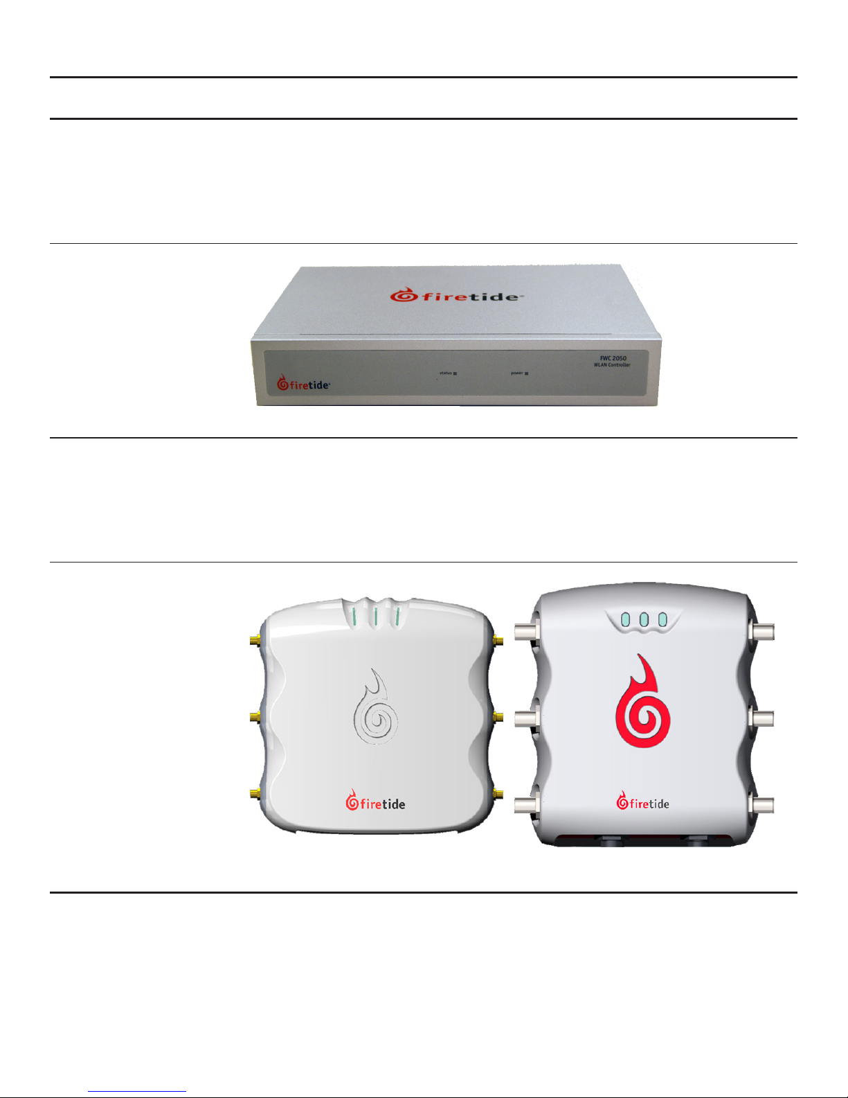
Figure 1. FWC2050 Controller
Setting Up Your Access Points
The HotPoint 5100 can be installed in any indoor location. The location should be selected based
on antenna and coverage plans - best RF performance is obtained with antennas connected directly
to the HotPoint AP, or with short, good-quality cables.
The HotPoint 5200 can be installed in any outdoor location. Again, location should be determined
by antenna and coverage needs, not by Ethernet or power availability.
Figure 2. Firetide HotPoint 5100 Indoor and 5200 Outdoor MIMO Access Points
Use with Firetide HotPort 7000 Mesh Nodes
In locations where access to Ethernet or power is limited, the HotPoint 5100 and 5200 can be
paired with a HotPort 7000 Mesh Node for backhaul. The HotPort 7201/7202 Series is also capable
of powering the HotPoint 5100/5200 Series.
Firetide - Reliable Connectivity Anywhere 5 January 2011

Chapter 3 Logging In
System Requirements
The FWC2050 Controller, if used, must have layer 2 or layer 3 connectivity to all Firetide 5000 series Access Points.
The system requires a DHCP server. If your network has one, it can be used. If desired, you can use the DHCP server built into the
FWC2050.
Logging In
The default IP address for the FWC2050 is 192.168.224.250.
Log in to your FWC2050 Wireless Management System administrative interface for the rst time at http://192.168.224.250,
using the default username (admin) and password (password)
Firetide recommends that you change the user name and password, and the default IP address.
6 HotPoint 5000 User Guide January 2011

Chapter 4 Access Point Tab
Discovery
Firetide HotPoint 5000 Access Points can operate as stand-alone devices, or be associated with Firetide Wireless Controllers. Controllerbased operation, called Managed Mode, offers many additional features, including roaming. The Controller can auto-discover and manage the access points in the same layer-2 domain, or across a layer-3 domain, but certain conditions must be met
Discovery for Initial Setup
New or factory-reset APs operate in stand-alone mode, unaware of the existence of the Controller. The Controller can discover these
units as long as they are on the same layer-2 subnet. Once an AP is discovered, it switches into Managed Mode. APs in Managed Mode
will look for a Controller whenever they reboot, using IP multicast.
Access Points in stand-alone mode (including any factory-reset APs) can only be discovered within the local subnet.
At the end of the discovery process, each discovered AP will be running a controller-based software image and will have attached itself
to the controller that discovered it. It will be ready to accept client connections.
Re-Discovery
Once an AP has been discovered, it remains a Managed AP until it is factory reset. Managed APs will actively look for the Controller after a reboot. This process uses IP multicast, and can work across multiple subnets, if you enable multicast routing for address
224.0.100.250 between controller and the APs. Alternately, you can enable DHCP option 43 on the DHCP server and provide the controller’s IP address. APs will get their address via this DHCP server and get the controller’s IP as part of the option 43.
For the discovery process to work, the FWC 2050 and the APs must be running compatible rmware versions. Contact Firetide for details
on rmware levels. In addition, DHCP service must be available, either from a system-wide DHCP server or via the DHCP service offered
by the FWC2050.
Last Discovered
The results of the auto-discovery are shown in the “Last Discovered” page under Discovery menu. Access Points can also be
added manually.
Conguration and Image Upgrade on the AP
After each reboot of an access point AP, the AP will look for its Controller, using multicast. Upon reconnecting, the AP and Controller
will re-synchronize on rmware levels and AP settings. As part of this state machine, the AP will load any new rmware image posted
to the controller. It will also synchronize to any conguration changes that were done on the controller while the AP was ofine.
Managed AP List
This displays a list of APs currently under management, and allows you to edit their settings.
Firetide - Reliable Connectivity Anywhere 7 January 2011
 Loading...