

Hot Melt Technologies BENCHMARK 205-LV4 Service Manual
BENCHMARK 205-LV4
SERVICE MANUAL
Your System Configuration
Tank Size
8 lb (3.6 kg) 1 gal (4.4 L)
Voltage Requirements
120 VAC, Single Phase, 20 A
Motor Rating
120 VAC, 43 RPM
1723 W. Hamlin Rd | Rochester Hills, MI 48309
248.853.2011 | www.hotmelt-tech.com

Product Introduction
Intended Use
Benchmark® and ProFlex® adhesive melters and components are designed to melt
and pump thermoplastic hotmelt adhesives and sealants. Any other use is considered
to be unintended. Hot Melt Technologies (HMT) will not be liable for personal
injury or property damage resulting from unintended use. Intended use includes
the observance of HMT safety instructions. HMT recommends obtaining detailed
information on the hotmelt materials being used.
The product is only intended for use in industrial applications and may
only be used to melt and pump thermoplastic hotmelt adhesives
(e.g. EVA, PSA, APO, Polyamid).
The product may only be installed, assembled, commissioned, operated,
maintained, repaired, de-commissioned and disposed of by trained
personnel.
The product may only be operated with compatible original components
and original accessories from Hot Melt Technologies Inc.
The product is to be used exclusively for the purpose described herein
and within the limits defined in this document. The product must not
be modified with respect to its structure or its safety features without
the written consent of Hot Melt Technologies. No changes to the
software or hardware of HMT products are permitted. Only use
original spare parts, original accessories or standard parts that
have been approved by HMT.
The instructions are part of this product. No applications other than those described
in the instructions are permitted.
Improper Use
Examples of misuse of the product include:
Melting and pumping of unsuitable adhesives
(e.g. PUR-Polyurethane hot melt adhesives)
In defective condition
With electrical cabinet open
With the tank lid open
Melting and pumping materials which, when under vacuum or pressure,
can pose a health hazard or endanger safety in the workplace
(e.g. solvents, explosive or highly flammable materials)
Cleaning the product with highly flammable materials (e.g. solvents)
Use in environments that require cleaning of the product with jets or
sprays of water
Processing of food
Residual Risks
In the design of the Benchmark and ProFlex systems, every measure was taken
to protect personnel from potential danger. However, some residual risks can
not be avoided:
Risk of burns from hot material
Risk of burns when filling the tank, from the tank lid, and from the hose
and gun exposed metal surfaces.
Risk of burns when conducting maintenance and repair work for which
the melter or components must be heated up.
Material fumes may be hazardous. Always avoid direct inhalation.
©2015 Hot Melt Technologies, Inc

Benchmark 205-LV4
Table of Contents .......................................................................................................... 3
Safety & Set Up ...........................................................................................................4-5
Operating Instructions.................................................................................................6-8
Front Panel Controls ...............................................................................................6-7
Adjusting Hose & Gun Temperatures .......................................................................8
Components ..............................................................................................................9-11
Exploded View ...........................................................................................................9
Tank & Pump Assembly ...........................................................................................10
Front Panel ..............................................................................................................11
Electrical ..................................................................................................................12-13
Fuse & Relay Chart ................................................................................................... 12
Schematic ................................................................................................................. 13
Hose Information ...................................................................................................14-15
Benchmark Series ....................................................................................................14
Proper Hose Usage ..................................................................................................15
Handgun Information .............................................................................................16-17
ETC Handgun ........................................................................................................... 16
ETC Handgun Parts List ...........................................................................................17
Nozzle Information .................................................................................................18-19
400 Series Extrusion Nozzles ................................................................................... 18
500 Series Extrusion Nozzles ................................................................................... 19
Accessory Information .................................................................................................. 20
LV/HV Optional Items ..............................................................................................20
DFS Kits ......................................................................................................................... 21
Warranty Information ..................................................................................................22
Technical Services & Support ........................................................................................ 23
©2015 Hot Melt Technologies, Inc Page 3

Safety & Set Up
Benchmark 205-LV4
STOP
STOP
If incorrectly used, this machine can cause severe injury.
Those who use and maintain the machine should be trained
in its proper use, warned of its dangers, and should read the
entire manual before attempting to set up, operate, adjust or
service the machine.
WARNING
Do not allow the pump motor to stall. A prolonged stall may damage
the motor and other components.
Do not connect or disconnect electrical connectors, or remove
components, with the power on. This will prevent arcing of electrical
contacts and possible failure of components.
Always close and secure the control panel access cover to protect
internal electrical components.
Always operate the system with the tank full and lid on.
Prior to dismantling, assembly, or adjustment of certain service parts
(hose/gun fittings, pump assemblies, etc.), the part(s) being serviced
should be preheated to reduce the chance of stripping threads or
ruining components.
Working on or around hot melt adhesives and equipment can cause
severe burns.
Use eye protection, gloves and protective clothing while operating
and/or servicing hot melt equipment.
Before installing any hot melt equipment, determine proper electrical
requirements per all applicable codes.
At Hot Melt Technologies, we pay special attention to the needs of
operators and service personnel when designing equipment, but
molten hot melt adhesives are dangerous and can cause severe burns.
Extreme care must be exercised to insure personnel safety.
Fire, explosion, personal injury, property, and/or equipment damage
can result if the material(s) used in or around any hot melt adhesive
supply unit are toxic, heat, or re sensitive. Always read the
manufacturer’s recommended use guidelines.
All HMT units are equipped with over temperature protection as
a necessary safety device. Run-away heating can cause hot melt
materials to exceed their flashpoint.
Page 4 ©2015 Hot Melt Technologies, Inc

Safety & Set Up
Benchmark 205-LV4
Before Using Your Hot Melt System
It is your responsibility and obligation to make sure your system:
Has been properly installed off the floor and on a steady,
level work surface away from combustible materials.
Has been located in such a way that the controls are away
from the operator and that the control panel is securely
closed at all times.
Is the right capacity system for the intended use.
Is connected to the proper power supply. (See Below).
Is only used to do what a hot melt system is designed to do.
Is not used by anyone unable to operate it properly.
Is used in an area where the room temperature does not
fall below 65 °F.
Is used in an area which is free from blowing air caused by
cooling fans, open doors or windows.
Power
Supply
Cord
20 Amp Connection
3 Prong
Grounding
Plug
Grounding
Prong
NEMA 5-20 Type
20 Amp Wall
Receptacle
Prevent Serious Equipment Damage
Protect your hot melt equipment by installing a GFEP
(Ground Fault Equipment Protector) device in your
distribution panel.
HMT recommends that hot melt systems be protected
from unintended line-to-ground currents by installing
an appropriate ground fault equipment protection
(GFEP) device. Contact HMT Technical Service & Support
or a qualied electrical contractor for more information.
When installing a GFEP device always comply with local
electrical codes.
Basic Electrical Power Connections
For 120 VAC Operation
A fused 20 amp 120 VAC electrical supply is required.
Performance problems will occur with voltages less than 108
VAC or greater than 132 VAC.
Total amperage draw will depend on the final system
configuration; number of hoses & length, guns, accessories, etc.
Do not allow the system to share the same circuit with other
electrical items. A dedicated supply is recommended.
Do not use an extension cord.
If you change the configuration of your system in any way
that may affect the electrical requirements (ex. add a gun,
longer hose, automate, etc.) call HMT Technical Service &
Support at 248-853-2011 for assistance.
©2015 Hot Melt Technologies, Inc Page 5
Operating Instructions
Benchmark 205-LV4
3
2
1
Main Power
Temperature Display
000
Set
Mode
Over
Temp
Pump
Ready
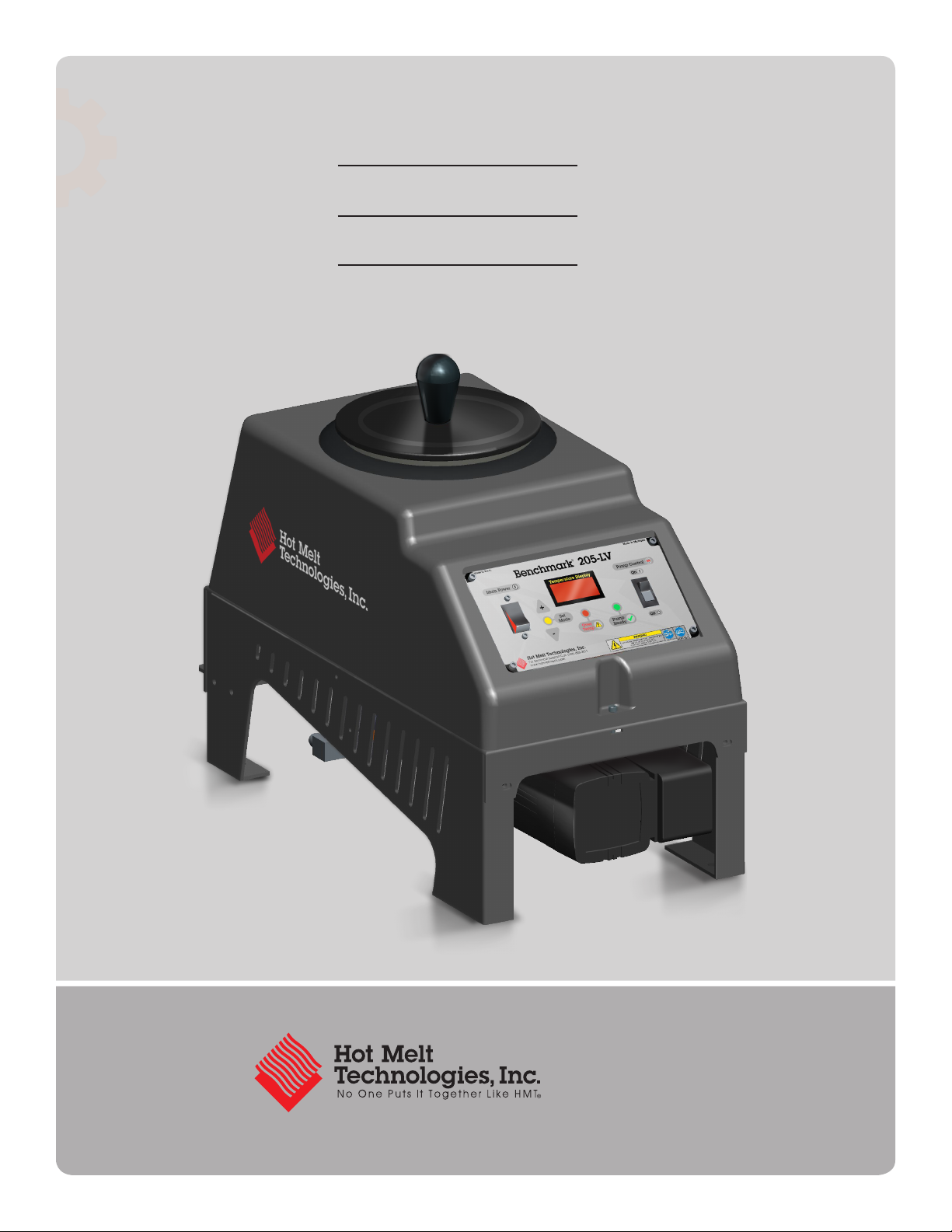
Front Panel Controls
4
5
Pump Control
On
Off
6
1
Main Power Switch: Turns the system “ON” or“OFF.”
To adjust the Tank Temperature Set Point: Press and hold the
2
“+” or “-” button for two (2) seconds to enter Set Mode. The Set Mode
LED will illuminate when Set Mode is active. While in Set Mode, use
the “+” or “-” button to change the tank temperature set point.
The tank temperature can be adjusted between 225°F and 400°F
(107°C and 204°C).
Temperature Display: Displays the tank temperature in °F or °C. If the
3
“+” or “-” button is pressed the tank temperature set point is displayed.
When released the Temperature Display will show the actual
tank temperature.
4
Over Temp: Over Temp occurs when the tank temperature reaches 425°F
(218°C). The Over Temp LED will ash red, for safety the system will shut
down, and “OFF” will be shown on the Temperature Display. Contact
Technical Service and Support for repair options.
5
Pump Ready: When the Pump Ready LED is illuminated, the pump
can be triggered on. The Pump Ready LED illuminates when the tank
temperature is within 25°F (14°C) of the tank temperature set point.
6
Pump Control “ON/OFF” Switch: Allows the pump motor to run
when triggered.
Page 6 ©2015 Hot Melt Technologies, Inc
Operating Instructions
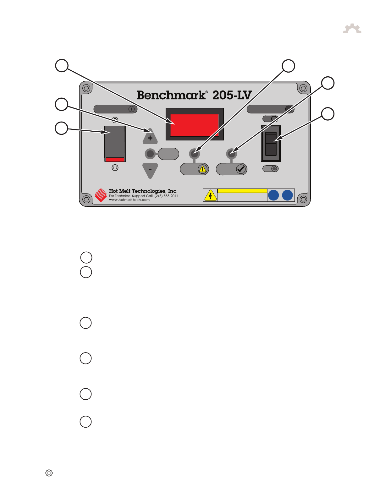
Front Panel Controls
Benchmark 205-LV4
OFF
OFF
SET LOCK
SET LOCK
DEG C
DEG C
ON
ON
8
245-101
7
7
Celsius: If the “Deg °C” switch is in the ON position, the temperature
display will show the tank temperature in °C.
Set Lock: If the “Set Lock” switch is in the ON position, Set Mode
8
cannot be activated and the tank temperature set point cannot be
changed. The Set Mode LED will not illuminate when the "set lock"
switch is ON.
©2015 Hot Melt Technologies, Inc Page 7
 Loading...