

Page 1
Operator’s Manual
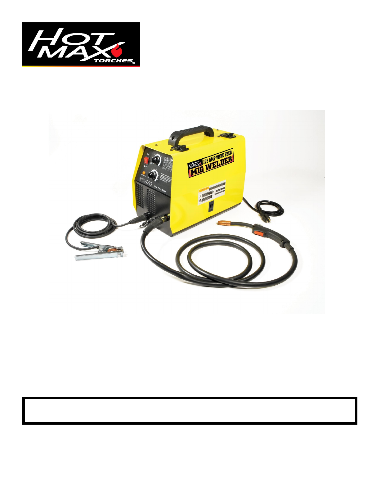
Model 125WFG
Wire Feed Welder
MIG Welders
WARNING: Do not assemble, install, or operate this equipment without reading ALL of this manual
and the safety precautions and warnings illustrated in this manual.
KDAR Company Tel: (314) 692-8555
1 Mulch Lane Fax: (314) 692-8578
St. Louis, MO 63044 Web Site: www.hotmaxtorches.com
Page 2
SAFETY PRECAUTIONS AND WARNINGS
PLEASE READ BEFORE USING EQUIPMENT
WARNING
ELECTRIC SHOCK CAN KILL.
The input circuits are live and hot when the power is on
Do not touch live electrical parts
Wear dry, hole free insulated work gloves and body protection when operating
Do not touch torch components if in contact with the work piece or ground
Always turn off power before cleaning, checking, or changing parts
Properly ground this piece of equipment per state and federal requirements
Inspect and replace any worn or damaged torch cables or leads
Keep all panels and covers securely in place
Keep away from the torch tip and weld arc when trigger is pressed
Ground the metal or work piece to the ground cable (Earth Clamp)
Never dip the tip into water to cool or attempt to use welder in or under water
This DC equipment holds a lot of power in the off position, before touching, make sure voltage is
near zero on input capacitors before touching any parts.
Keep children away from this equipment
Protect yourself and others from possible injury
Pacemaker wearers should consult with their doctor before operating
Read and follow all instructions in this manual before operating
All installation, operation, and maintenance procedures are to be
performed only by qualified individuals
ARC RAYS CAN BURN SKIN AND EYES
Arc rays when welding produce intense ultraviolet and infrared rays that can burn skin and eyes
Wear face protection, either helmet or shield, when operating. ANSI Z49.1 approved shade #9
recommended for all cutting currents less than 300 amperes. The lens should conform to ANSI
Z87.1 standards for testing.
Wear approved safety glasses with side shields under the face protection
Warn others not to stare at the arc as it can cause damage to the eyes. Provide barriers to protect
other workers in the area from the arc while operating
Wear flame resistant gloves, clothing, and shoes when operating
FUMES AND GASES CAN BE HAZARDOUS
Arc welding produces fumes and gases and breathing these gases is hazardous to your health
Keep your head out of the fumes and do not breath the fumes while welding
Work only in a confined area if it has sufficient ventilation, or while wearing an air supplied
respirator. Fumes from welding deplete the oxygen supply and can be harmful. Always be sure
there is ample breathing air
Read the MSDS sheets and the instructions from manufacturers for metals to be welded, coatings,
and cleaners
Do not use the welder near hydrocarbon vapors coming from degreasing, cleaning, or spraying
operations. The heat and rays can react with solvent vapors to create the gas phosgene, a very toxic
gas and other irritating gases
Do not weld coated metals, such as galvanized, lead, or cadmium plated steel. Before welding, all
plating must be removed. The area must be well ventilated or an air supplied hood must be used.
The coatings and chemicals when burned cause highly irritating and toxic fumes.
Do not weld containers with toxic, flammable, or reactive elements stored in them. They must be
emptied and properly prepared before welding.
KDAR Company 1
Page 3
WELDING SPARKS CAN CAUSE INJURY, FIRE, OR EXPLOSION
Remove all flammable materials from the welding area
Always have a charged fire extinguisher available in the welding area
When not welding make sure the welding tip is not grounded, this causes a heat build up and
possible fire
Avoid welding near hydraulic lines, fuel lines, electrical cords, air hoses, or welding guns and
cables
Sparks and hot metal fly out from the work area when welding, wear approved safety glasses with
side shields under approved helmets, wear proper body and hand protection, and wear flame
resistant ear plugs to keep sparks from entering the ears
CYLINDERS CAN EXPLODE IF DAMAGED
Gas cylinders contain gas under very high pressure. If damaged they can result in that cylinder
exploding. Gas cylinders are a major part of metalworking and must be treated with care.
Protect gas cylinders from excessive heat, mechanical shocks, slag, open flames, sparks, and arcs
Always keep cylinders in an upright position securely fastened to a fixed support
Valve protection caps should always be in place and hand tight except when the cylinder is in use
Keep all cylinders away from any welding or electrical circuits
Never allow the arc from a welder to contact a cylinder
Never cut any type of pressurized cylinder, an explosion could result
Always turn your face away from the valve when opening the cylinder
Read and follow all instructions on compressed gas cylinders, associated equipment, and CGA
publication P-1 listed in the Safety Standards before using
ELECTRIC AND MAGNETIC FIELDS MAY BE DANGEROUS
Electric current used in arc welding can create Electro-Magnetic Fields (EMF)
Magnetic fields can affect pacemakers and wearers should avoid proximity to EMF. Wearers need
to contact their doctors before operating this type of equipment
Exposure to EMF during operation of this equipment may have other health effects which are not
yet known
Route the work and torch cables together and not around your body
Do not place your body between the torch cable and the ground cable. They both need to be on the
same side of your body when operating
Do not work next to the welding machine
ELECTRICALLY POWERED EQUIPMENT
Disconnect power source or turn off the breaker in the power panel before working on any
equipment
Only install equipment using the US National Electrical Code, all local codes, and the man-
ufacturer’s recommendations
HOT PARTS CAN CAUSE SERIOUS BURNS
Do not touch hot parts without wearing protection.
Allow the torch to cool sufficiently before working with parts that could potentially be hot.
KDAR Company 2
Page 4
NOISE CAN DAMAGE HEARING
Prolonged noise exposure from welding equipment can cause damage if levels of noise exceed the
OSHA standards
Wear approved hearing protectors
Warn other workers nearby of the high noise level and hazard
CALIFORNIA PROPOSITION 65 WARNINGS
Welding or cutting equipment produces fumes or gases which contain chemicals known to the State of California to cause
birth defects, and in some cases, cancer. (California Health and Safety Code Section 25249.5 et seq.)
PRINCIPAL SAFETY STANDARDS
AMERICAN WELDING SOCIETY
AWS C5.2, Recommended Practices for Plasma Arc Cutting
AWS F4.1, Recommended Safe Practices for the Preparation for Welding and Cutting
OSHA STANDARDS
OSHA 29 CFR 1910, Safety and Health Standards
NATIONAL FIRE PROTECTION ASSOCIATION
NFPA Standard 70, National Electric Code
NFPA Standard 51B, Cutting and Welding Processes
AMERICAN NATIONAL STANDARDS INSTITUTE
ANSI Standard Z87.1, Safe Practices for Occupation and Educational Eye and Face Protection
ANSI Standard Z49.1, Safety in Welding and Cutting
KDAR Company 3
Page 5

Specifications
Rated input 115VAC, 60 hertz, 18 amps
Maximum output open-circuit voltage 28 volts DC
Rated output 80 AMPS@18volts 20%duty cycle
Wire feed rate 59 to 393 in/min (1.5-10.0m/min)
Specifications of applicable welding
wire
Welding Wire Spool 8”x2” (200mmx50mm)
Weight 54 lb (24.5 kg)
Dimensions (Length*Width*Height) 16”x9.6”x14.5” (408x244x367)
Features & Benefits
Light weight, small size all steel case.
Easy to use.
MIG/MAG ready, regulator and 5’ hose in-
cluded.
Optional spool gun available.
Infinite output voltage level.
Infinite wire feed speed control.
Wire at gun is “cold” when not welding.
Power on indicator light and overload indicator
light equipped.
Fan cooled.
20% duty cycle minimum.
Welds 22 gauge to 5/16” with flux cored wire.
Built in wire feeder with easy to use tension
adjustment lever.
Dual size groove drive roller to fit sizes .23”
to .35” wire (.6 to .9 mm).
.025”-.030” (0.6-0.8mm) solid steel
.030”-.035” (0.8-0.9mm) Flux-Cored
4”x2” (100mmx50mm)
Table 1
Easy polarity change for switching to and from
gas.
Flux covered (FCAW) set up from the factory,
ready to weld.
Welds steel, aluminum, and stainless (special
gas required for aluminum and stainless).
2 year limited warranty on the machine.
90 day limited warranty on gun and hose.
Comes with the following components.
2 replacement tips
Hex wrench to change wire feed roller.
Gas nozzle for MIG welding.
10# spool adaptor.
Gas regulator
5’ gas hose
2# Reel of .030” Flux Core Wire
KDAR Company 4
Page 6

Safety Considerations
Warning
Electric Shock Can Kill
Only qualified personnel should attempt to install this equipment.
Turn off the input power at the power panel or disconnect switch and discharge
capacitors before working inside the equipment.
Take care not to touch electrically hot parts
Make sure the unit is switched off before plugging it into a the power outlet.
Package Contents
Installation/Setup
KDAR Company 5
Page 7

Installation/Setup
Selecting A Location
The 125WFG Welder should be placed where clean cool air can easily flow through the vents in the front of
the unit. Dirt and dust can be drawn into the unit resulting in excessive operating temperatures and shutdowns,
therefore, dirt and dust around the unit should be kept to a minimum.
The 125WFG Welder should be placed on a stable, level surface suitable to hold the unit’s weight.
Components and Controls
1. Output voltage adjust knob
2. Power switch
3. Wire feed rate adjust knob
4. Thermal overload indicator
5. Ground clamp connection port
6. Gun trigger lead connectors
7. Door latch
8. Ground (work) clamp and cable
9. Welding gun and cable assembly
10. Overload reset button - the protector will
cut off the circuit if the welding machine
is in excess of the maximum load, after
which the switch must be manually reset.
11. Power Cord
12. Shielding gas inlet fitting
13. Spool gun selection switch
14. Positive (+) and Negative (-) output
terminals
15. Wing nut to secure welding gun
16. Wire feed gearbox
17. Wire spool spindle/shaft
6 KDAR Company
Page 8

Installation/Setup
Warning
Always unplug the welder before connecting or disconnecting the Ground Clamp cable
and/or the Gun Cable.
Ground Clamp & Lead Connection
1. Ground Cable Attachment: Th e Hot Max MI G
Welders use a convenient 1/4 turn connection for
attaching the ground cable to the unit. Insert the
male end of the ground cable into the female connection port (1) and turn 1/4 turn clockwise.
2. For FCAW (Flux Cored Arc Welding) Only:
The WFG series of welders are delivered set up for
FCAW welding with negative electrode polarity.
The cable coming out of the wing nut (6) on the
connector block is attached to the negative (-) output terminal and the ground lead is connected to
the positive (+) terminal.
3. GMAW (Gas Metal Arc Welding) Only: To set
up for GMAW welding with positive electrode polarity, connect the cable coming from the wing nut
(6) on the connector block to the positive (+) output terminal and the ground lead to the negative (-)
output terminal. Make sure all connections are
tight.
4. Gun Selection: Select standar d gun or optional
spool gun using the gun selector switch (4).
Figure C-1
Gun Installation
1. Insert the male connector on the gun cable into the
gun cable connection port (3). With the connector
all the way in the connector block tighten the wing
nut (6) to secure the gun.
2. Connect the gun lead terminal to the gun lead connector (2).
KDAR Company 7
Page 9

Installation/Setup
Gas Connection
Warning
Cylinder can explode if damaged. Keep cylinder chained upright to a secure support.
Keep cylinder away from areas where it could be damaged.
Never lift or move the welder with the cylinder attached.
Do not let the welding electrode touch the cylinder.
Keep the cylinder away from welding or other live circuits.
Shielding Gas may be harmful to health or cause death.
Turn off gas supply when not in use.
Refer to American National Standard Z-49.1, “Safety in Welding and Cutting” from the Amer-
ican Welding Society for more information.
Gas Hook Up
When using the GMAW process, a cylinder of shielding gas must be used. Shielding gas cylinders and gas can
be obtained at a local gas supply company or some farm supply stores. The recommended gases for the Hot
Max 125MIG welder is either Welding grade CO2 or a Argon/CO2 blend with 75-80% Argon and 20-25%
CO2 (see Suggested Settings chart on the welder compartment door).
1. Insure the cylinder is properly secured to a wall or other stationary support to prevent it from falling over
during setup or operation. Be sure the cylinder is insulated from the work circuit and ground.
2. Once the cylinder is properly secured,
remove the cylinder cap. Standing to one
side slowly open the cylinder valve for an
instant to blow away any debris that may
have accumulated in the valve outlet.
3. Attach the flow regulator to the cylinder
valve and tighten with a wrench.
4. Attach one end of the gas hose to the output fitting of the regulator and tighten
securely with a wrench.
5. Test to insure the flow regulator is closed
by opening cylinder valve slightly. If the
regulator is not closed turn the black
knob counter clockwise until the flow of
gas has stopped.
6. Connect the other end of the hose to the
gas inlet fitting on the 125WFG welder
making sure that the hose is not kinked or
twisted.
KDAR Company 8
Page 10

Installation/Setup
Gas Hook Up (cont.)
7. Reopen the regulator valve until the flow indicator shows
15 L/min (initial flow setting). The setting may need to be
adjusted by the operator to compensate for welding conditions.
8. Always close the cylinder valve and open the regulator
valve when not in use.
Input Connections
The 125WFG welder has power input cables located on the rear of the unit.
KDAR Company 9
Page 11

Safety Considerations
Warning
Electric Shock Can Kill
Do not touch live electrical parts of the electrode with skin or wet clothing.
Insulate yourself from work and ground.
Always wear insulated gloves and keep them dry.
Fumes & Gases Can Be Hazardous
Plasma cutter should only be used in a well ventilated area or with an exhaust
system.
Keep your head away from the fumes.
Operation
Arc Rays Can Burn Skin and Eyes
Always were eye, ear and body protection.
Cutting Sparks Can Cause Injury, Fire , or Explosion
Do not use near flammable material.
Do not cut or gouge on containers that have held combustibles.
KDAR Company 10
Page 12

Operation
Controls
1. Output Voltage Control—The Hot Max infinite
setting output voltage control knob adjusts to any
setting from 25 to 125 amps. Additionally, the
voltage can be adjusted while welding.
2. Power On/Off Switch—A light within the switch
will be illuminated and the cooling fan will run
when the power is on.
3. Speed Control—Controls the wire feed speed.
The control can be preset on the dial to the setting
specified on the application chart located inside the
wire feed section door.
4. Overload Indicator—This LED comes on to indicate the duty cycle had been exceeded. Output will
be shut off until the unit has cooled to an acceptable operating temperature. The fan will continue to
run.
9. Gun Trigger—Pressing the trigger activates the
welding output, wire feed and gas operation. Re-
leasing the trigger stops the welding output, wire
feed and gas operation. Releasing the trigger also
starts the burn back function to prevent the welding wire from sticking to the working weld.
10. Overload Breaker—This breaker protects the unit
from damage due to exceeding the maximum output. The breaker pops out when tripped and must
be pushed in to be reset.
KDAR Company 11
Page 13

Operation
Use the welding wire board
with 4 "(100 mm) in diameter
Figure D-2
4
7
6
5
Use the welding wire board
with 8 "(200 mm) in diameter
Figure D-1
2
1
3
Loading Wire
Note: Always tur n power off when wor king inside
the welder enclosure.
8” Diameter Spool
1. Remove the wing nut (5), and plastic tension spacer (6).
2. Place the spool adaptor (2) over the shaft as
shown.
3. Replace spacer and wing nut. Make sure the wing
nut is positioned so that it does not interfere with
the locking tab.
4. Place spool on the spool adaptor making sure the
hole in the spool engages the stud (3) on the spool
adaptor and the spool slides completely over the
locking tab.
4” Diameter Spool
1. Remove wing nut (5) and the plastic tension spacer
(6).
2. Place the spool (label out) on the shaft with the
wire feeding from under the spool.
3. Replace the spacer, washer and wing nut
Adjusting Friction Break
While turning the spool with one hand begin tightening the wing nut with the other. Once you start to feel
tension; then turn the wing nut an additional 1/4 to 1/2
turn.
The intent is for the friction break to produce just
enough friction to prevent the spool from continuing
to turn after the drive motor has stopped.
KDAR Company 12
Page 14

Operation
Wire Feeding
1. Release the spring loaded tension arm (1) by flipping it to the right and down.
2. Lift the idle arm (2).
3. Make sure the grove size on the drive roll (5) is in
the feeding position that matches the wire size being used. Refer to the Suggested Settings for
Welding chart at the back of this manual or on the
inside of the welder compartment door.
4. Detach the end of the wire from the spool and clip
a small amount of wire to get a good straight start.
Note: In or der to p r event the spool from un-
winding; it is important to keep tension on the wire
until after the idle arm and tension arm are back in
place.
5. Thread the wire through the inlet tube (4), over the
drive roll (5) and into the outlet guide tube (6).
6. Close the idle arm (2).
7. Move the spring loaded tension arm (1) into position.
8. If required, rotate the wire spool counter clockwise
to take up any slack in the wire.
9. If feeding problem occur because the wire is excessively flattened, turn the wing nut on the spring
loaded tension arm (1) counter clockwise to reduce
the pressure. If the drive roll (5) is slipping while
feeding the wire; turn the wing nut clockwise to
create more tension on the wire.
10. Remove nozzle (7) and contact tip (8) from
end of gun.
11. Turn on the Hot Max 125WFG.
12. With the gun cable assembly straight; press the
trigger switch. The welding wire will feed
through the cable and gun. Release the trigger
when the wire has fed approximately 2 inches
past the end of the gun.
13. Turn off the Hot Max 125WFG.
14. Replace the contact tip (8) and nozzle (7)
15. Cut wire off approximately 3/8” from the end
of the contact tip. The Hot Max 125WFG is
ready for welding.
Warning
When feeding the wire, the drive roll, the connector
block and gun contact tip are electrically charged
relative to work and ground and remain charged
for several seconds after the gun trigger is released.
KDAR Company 13
8 7
Figure 13
Page 15

Operation
Welding
1. See Suggested Settings at the back of this manual
or on the inside of the wire feed compartment door
for welding wire and shielding gas recommendations.
2 See Suggested Settings for information on setting
the controls on the Hot Max 125WFG for specific
welding wire and metal thickness.
3. Set the voltage and wire speed.
4. Insure the unit is set up for the correct polarity for
the welding wire and process being used. The Hot
Max 125WFG is shipped set up for FCAW (Flux
Cored Arc Welding)
5. Insure the proper nozzle and tip are installed on the
gun for the welding wire and process being used.
6. If required, turn on gas supply.
7. Connect the ground clamp to the metal being
welded. The clamp must make a good connection.
8. Position the gun of the joint to be welded. The
wire can touch the metal lightly.
9. Lower the welding helmet, pull the trigger on the
gun and start welding. The contact tip should be
about 3/8” from the work surface.
10. Release the trigger to stop welding and pull the
gun away from the work after the arc has stopped.
11. If there is no more welding to be done, close the
valve on the gas cylinder (if gas was used) and pull
the trigger on the gun to release the gas pressure
and then turn off the Hot Max 125WFG.
Changing the Welder for Feeding
Different Wire Sizes
The Hot Max 125WFG is shipped ready to
run .030” gasless flux cored wire. To run other sizes of wire the contact tip must be changed and the
drive feed roll may need to be changed.
Changing the Contact Tip
1. To change the contact tip (1) you must first
remove the nozzle (2). This is done by un-
screwing it counter clockwise.
2. Unscrew the contact tip counter clockwise.
3. Screw in selected contact tip clockwise. Hand
tighten only.
4. Replace nozzle by screwing on clockwise.
2 1
Figure 14
KDAR Company 14
Page 16

Operation
Shielding
Proce ss Welding Wire Gas 16 ga 14 ga 12 ga 10 ga
MIG DC+
.035 Dia 4043
Aluminum Wire
100% Argon B-5.5 C-7 C-9 C-9
MIG DC+
.035 Dia 5356
Aluminum Wire
100% Argon B-5.5 C-8 C-9 C-10
MIG DC+
.030 Dia 308L
Stainless Steel
Wire
98% Argon/
2% Oxygen
A-3 C-7 C-7 C-7
Voltage/Wire Spee d
Changing Drive Roll
The drive roll has two groves; the smaller grove is
for .023” - .025” welding wire and the larger grove is
for .030” - .035” welding wire. The welder is shipped
set up for the larger welding wire sizes.
To change the drive roll position:
1. Connect the unit to the appropriate power source.
2. Open the wire drive compartment door, release the
spring loaded tension arm (1) by flipping it to the
right and down and lift the idle arm (2).
3. Turn the power on.
4. Turn the feed control speed to the minimum setting and momentarily pull the trigger to turn the
drive roll (4). Stop when the set screw (3) is facing
up.
Warning
When feeding the wire, the drive roll, the connector
block and gun contact tip are electrically charged
relative to work and ground and remain charged
for several seconds after the gun trigger is released.
5. Turn the power off.
6. Loosen the drive roll set screw (3) with the hex
wrench provided with the Hot Max 125WFG.
7. Remove the drive roll (4) turn it around and put it
back on the shaft.
8. Cut and straighten about 5” of the desired wire and
feed it through the wire inlet tube and into the outlet tube. Line up the drive roll grove with the
welding wire and tighten with the hex wrench.
Make sure the set screw is on the flat part of the
shaft.
Aluminum & Stainless Steel Wire
The Hot Max 125WFG is capable of welding with
both .035” aluminum and .030” stainless steel
welding wire. See the table below for welder settings for these wires.
Table 2
KDAR Company 15
Page 17

Maintenance
Warning
Electrical Shock Can Kill
Disconnect from the input power source prior to working inside the Hot Max
125WFG.
Allow only qualified personnel to do maintenance and trouble shooting.
General Maintenance
Power Supply Compartment
The Hot Max 125WFG does not have any serviceable
parts inside the power supply compartment. Do not
attempt to service parts in the power supply compartment. Contact KDAR Company for instructions if
you have problems that can not be corrected by following the trouble shooting instructions.
If you are working in dusty areas, dirt may get into
the air vents and cause the welder to run hot and trip
the thermal overload protection. If this happens, blow
the dirt out with low pressure air regularly.
Wire Feed Compartment
1. Occasionally dirt will accumulate in the wire feed
compartment. When this happens, simply vacuum
the dirt out of the compartment.
2. Each time the wire spool is changed, inspect the
inside diameter of the wire feed inlet tube. If necessary, clean the inside of the tube.
3. The motor and gearbox needs no lubrication or
maintenance.
Wire Spool Shaft
Requires no maintenance. Do Not Lubricate.
Gun Cable
1. To clean the cable liner, remove the gun cable
assembly from the welder and lay it out
straight on the floor.
2. Take the contact tip off of the gun. Blow low
pressure air through the liner from the gun end
of the liner.
3. Flex the cable over its entire length and blow
air through again. Repeat flexing the cable and
blowing air through until no dirt comes out.
Contact Tip & Nozzle
1. When dirt builds up in the contact tip hole,
wire feeding can be restricted. To clean the tip,
run the appropriate sized tip cleaner through
the tip repeatedly. This should remove any dirt
that has built up on the walls of the contact tip.
KDAR Company tip cleaner number 22034 is
available for selected distributors or hotmax-
torches.com.
2. Remove splatter from the inside gas nozzle and
the tip frequently.
KDAR Company 16
Page 18

Troubleshooting
Warning
Most components of the 125WFG welder are not serviceable by the operator and should only be serviced by a qualified repair technician. Unauthorized repairs to these units may result in danger to the
operator and will void the factory warranty. For your safety, please follow all safety precautions found
throughout this manual.
Problem
Nothing happens when the trigger is pulled; no wire
feed, weld output or gas flow. Fan is not operating.
When trigger is pulled there is no wire feed, weld
output or gas flow but the fan operates.
Little or no gas flow is evident when the trigger is
pulled. Wire feed, weld output and fan operate as
normal.
No wire feed when the trigger is pulled but the fan
runs, gas flows and there is weld output.
Possible Cause
1. Check to insure the power switch is turned on.
2. Insure correct voltage is applied to the welder.
3. Check to insure the circuit breaker is not
tripped.
1. The welder may have overheated and tripped
the thermostat. Let the welder cool down and
weld at a lower amperage setting.
2. Check for obstructions in the air flow and to
insure the gun cable assembly connections are
correct.
3. Gun trigger may not operate properly.
1. Check to insure the gas supply is adequate.
2. Check the regulator and gas hoses to insure
there are no problems.
3. Check to insure there are no obstructions or
leaky seals in the gun cable assembly connection.
1. Check to see if the wire drive motor is turning.
If it is, make sure the drive roll is the correct
size and is installed properly.
2. Check to insure the cable liner and/or tip is not
clogged and is sized correctly.
3. Check to insure the Spool Gun Selection switch
is set to the correct position.
KDAR Company 17
Page 19

Troubleshooting
Problem
Arc is unstable—Poor starting
Possible Cause
1. Check to insure proper input voltage to the welder.
2. Check electrode polarity to make sure it is correct for the process being used.
3. Check tip for proper size and damage; replace if
necessary.
4. Insure proper gas flow for the process.
5. Make sure the connections for the ground cable
are correct.
6. Make sure the drive roll is installed and aligned
properly.
7. Make sure the wire size is correct and there is no
damage to the gun cable assembly.
Note: For problems that can not be corrected by following the troubleshooting proce-
dures listed above; please contact KDAR Company. NEVER attempt to work on any part
of the welder not listed above. Unauthorized repairs to the unit may result in danger to
the operator and will void the factory warranty.
KDAR Company 18
Page 20

Warranty
KDAR Company, and its affiliates, warrants that
all welders covered under this warranty is free
from defects in material and workmanship for one
year from the date of purchase. KDAR also warrants that all guns, hoses and ground clamp assemblies are free from defects in material and
workmanship for 90 days from the date of purchase. This warranty is extended to the original
purchaser who uses the product in a consumer
application (personal, residential or household
usage). All welders covered under this limited
warranty which are used in commercial applica-
tions (i.e. income producing) are warranted to be
free from defects in material and workmanship
for 90 days from the date of original purchase.
The products covered under this warranty are the
125WFG, 135WFG and 175WFG welders.
KDAR Company, and its affiliates, will repair or
replace, at KDAR’s sole discretion, parts found to
be defective in material or workmanship within
the warranty period. Warranty service will be
scheduled according to the normal work flow and
business hours of the service center doing the
work as well as the availability of replacement
parts. All decisions from KDAR Company regarding this limited warranty shall be final.
Original Purchaser’s Responsibility:
1. Retain the original cash register receipt as
proof of purchase.
2. Follow manual instructions regarding the care
and operation of your welder.
3. If warranty work is required, DO NOT RE-
TURN THIS WELDER TO THE RETAILER. Contact KDAR Company for instr uc-
tions. Visit www.hotmaxtorches.com or call
KDAR Company M-F 8AM-5PM CST to locate the nearest Authorized Service Center.
Not Covered:
1. Transportation charges for sending or delivering the welder to the Authorized Service Center or returning the repaired or replacement
welder back to the customer. These charges are
the responsibility of the customer.
2. Damages caused by ordinary wear, abuse, rain,
freeze damage, negligence, accident or failure
to operate or maintain the welder in accordance
with the instructions in the operator’s manual
supplied with the welder.
3. Damage caused by unauthorized repair or al-
terations.
Exclusions and Limitations:
KDAR Company makes no other warranty of
any kind, express or implied. Implied warranties, including warranties of merchantability
and of fitness for a particular purpose, are
hereby disclaimed. The warranty service described above is the exclusive remedy under
this warranty; liability for incidental and conse-
quential damages is excluded to the extent per-
mitted by law.
This warranty gives you specific legal rights, and
you may have other rights which vary from state to
state. Some states do not allow a disclaimer of implied warranties, or the exclusion of incidental and
consequential damages, so the above disclaimers
and exclusions may not apply to you.
For warranty service or to obtain service parts
or accessories:
Call: (314) 692-8555 M-F 8-5 PM, CST
Visit: www.hotmaxtorches.com
Write: KDAR Company
1 Mulch Lane
St. Louis, MO 63044
KDAR Company
1 Mulch Lane
St. Louis, MO 63044
Phone: (314) 692-8555 Fax: (314) 692-8578
Rev. 4 - Nov 2013
 Loading...