

Page 1
Assembly Instructions & Parts List
Dual Purpose Red Cart
Model 100MC
WARNING: Read and follow ALL instructions and warnings for the equipment that is
used on this cart before operating that equipment.
KDAR Company
1 Mulch Lane
St. Louis , MO 63044
Tel: (314) 692-8555
Fax: (314) 692-8578
Web: www.hotmaxtorches.com
Page 2
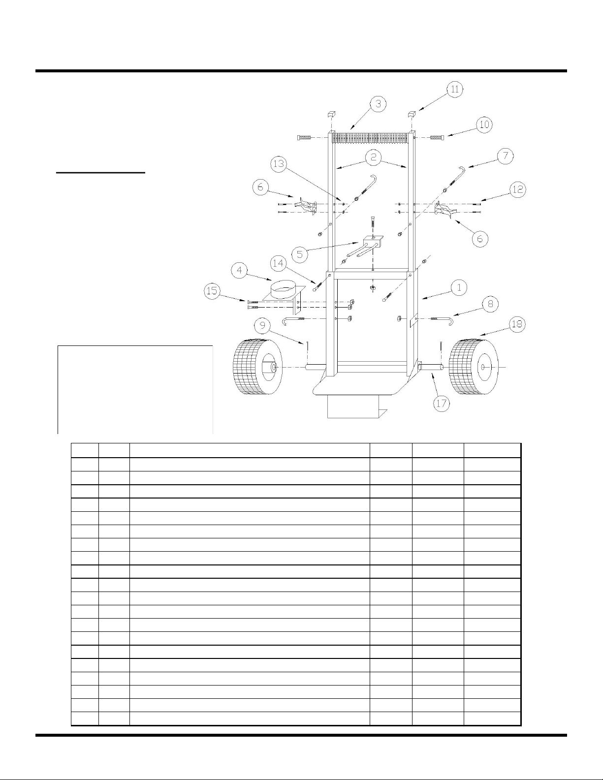
Item QTY Description Length Diameter Head Size
1 1 Welded Base Frame
2 2 Handle Uprights (Identical)
3 1 Molded Handle
4 1 Cup Holder Bracket For Big Max Family Torches
5 1 Finger Holder For MM-1 Mobile Max
6 2 Spring Clips
7 2 Long J-Hooks (6 mm) 4-1/8" 6 mm
8 1 Short J-Hooks For Straps (6 mm) 2-1/2" 6 mm
9 2 Cotter Pins For Wheel Axle 1-1/2" 1/8"
10 2 Chrome Bolts For Molded Handle 1-1/4" 3/8" 9/16"
11 2 Black Caps For Top of Handle Uprights
12 4 5 x 32 mm Philips Head Screws for Spring Clips 32 mm 5 mm Phillips
13 4 5 mm Nylon Insert Lock Nuts for Spring Clips
14 2 6 x 38 mm Bolts for Handle Uprights 38 mm 6 mm 10 mm
15 3 6 x 34 mm Bolts 34 mm 6 mm 10 mm
16 11 6 mm Nuts 6 mm 10 mm
17 1 Steel Axle 1/2"
18 2 Pneumatic Tires
19 1 1" Red Strap w/Loop End & Buckle
20 1 1" Red Strap w/Loop End, No Buckle
Tools Required
10 mm Wrench
8 mm Wrench
9/16” Wrench
Phillips Screwdriver
Pliers
Hammer (Optional)
Assembly Instructions
If you think you are missing
any parts or have trouble
assembling the cart, please call
KDAR Company at (314) 692-
8555 M-F 8 AM to 4 PM CST
for assistance.
KDAR Company 1
Page 3
Assembly Instructions
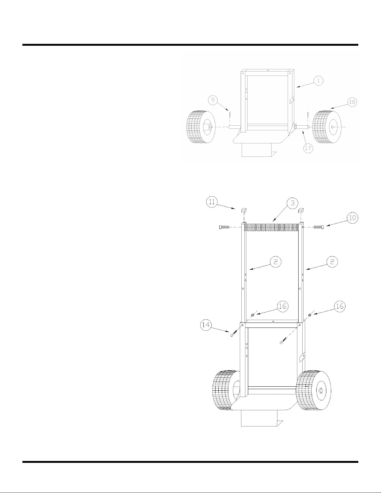
Step 1
After removing all components out of the box,
locate the welded base frame (Item 1), two pneumatic tires (Item 18) , steel axle (Item 17), and
two cotter pins (Item 9). Note: The axle is often
shipped inside the welded base frame. Slide the
axle through the hole in the bottom of the welded
frame (sometimes paint makes this whole smaller
so you might need to use a hammer to get it in).
Slide the wheels over the axle on either side (hubs
in) of the base frame . Slide the cotter pins
through the small hole in the axle to secure the
wheels to the axle.
Step 2
Locate the two handle uprights (Item2), molded
handle (Item 3), and chrome bolts for the handle
(Item 10). Insert the chrome bolt (Item 10)
through the handle upright (Item 2) and into the
molded handle (Item 3) and hand tighten this bolt.
Bolt the opposite the handle upright to the handle
as well. Insert both handle uprights (Item 2) into
the welded base frame until the bolt holes line up.
Insert a 6 x 38 mm bolt from the front through
both the base frame and the handle uprights.
Sometime excess paint makes the bolts hard to
get in so use a wrench to thread them into the
hole. Place a 6 mm nut (Item 16) on the bolt and
hand tighten. Repeat the with another 6 x 38 mm
bolt and nut on the other side.
Note: It’s easy to not notice that there are two siz-
es of 6 mm bolts: 6 x 38 mm and 6 x 34 mm.
There are two 38 mm bolts (Item 14) and three
34 mm bolts (Item 15). If you place a bolt in a
location and it doesn’t seem long enough, double
check that you have the correct bolt.
KDAR Company 2
Page 4

Assembly Instructions
Step 3
Attach the Cup Holder Bracket (Item 4) to the
welded base frame with two 6 x 34 mm bolts
(Item 15) and two 6 mm nuts (Item 16).
Step 4
Attach the short J-Hooks (Item 8) to the welded
base frame and thread on 6 mm nuts (Item 16).
Hand tighten these as the straps will be installed
later.
KDAR Company 3
Page 5

Assembly Instructions
Step 5
Attach the spring clips (Item 6) to the handle uprights with two 5 x 32 mm Philips head machine
screws (Item 12) and 5 mm nuts (Item 13). Tighten these all the way with a Philips screw driver
and a 8 mm wrench.
Step 6
Thread a 6 mm nut onto the long J-Hooks (Item
7) until it reaches the end of the threads (flat part
of the nut head towards the handle. Insert the
long J-Hook (Item 7) into the handle uprights and
thread on another 6 mm nut (Item 16) on the front
of the cart just until the threads come all the way
through the nut. Now tighten the nut on the back
with a 10 mm wrench until tight. Repeat for the
other side.
KDAR Company 4
Page 6

Assembly Instructions
Step 7 - For Use with MM-1 Mobile
Max Torch Kits
Attach finger holder bracket (Item 5) with a 6 x
34 mm bolt (Item 15) and 6 mm nut (Item 16).
Note: If you plan to use the cart with a propane
tank, you may find that the finger holder bracket
is in the way so you may not want to install this
bracket.
Step 8
Now it is time to install your MM-1 Mobile Max
Torch Kit or your 20# or 40# propane tank.
For the MM-1 Mobile Max, place the handle of
the tote over the finger holder and let the bottom
of the tote rest on the platform. Secure the tote
with the two red straps attached at the loops to the
short J-Hooks on the base frame. Make sure the
buckle tightens down on the opposite strap and
holds the MM-1 in place.
For the propane tank installation, simply place the
tank on the platform and secure the tank with the
two red straps attached at the loops to the short JHooks on the base frame. Make sure the buckle
tightens down on the opposite strap and holds the
tank in place.
Assembly is complete!
KDAR Company 5
Page 7

Product Pictures
100MC Red Cart with
Big Max Torch
100MC Red Cart with
MM-1 Mobile Max Torch
Kit
KDAR Company 6
Page 8

Warranty
KDAR Company, and its affiliates, warrants that
all carts covered under this warranty is free from
defects in material and workmanship for one year
from the date of purchase. This warranty is extended to the original purchaser who uses the
product in a consumer application (personal, residential or household usage). All carts covered under this limited warranty which are used in commercial applications (i.e. income producing) are
warranted to be free from defects in material and
workmanship for 90 days from the date of origi-
nal purchase. The products covered under this
warranty are the 100MC dual purpose red cart
and WC100 welding/plasma cutter cart.
KDAR Company, and its affiliates, will repair or
replace, at KDAR’s sole discretion, parts found to
be defective in material or workmanship within
the warranty period. Warranty service will be
scheduled according to the normal work flow and
business hours of the service center doing the
work as well as the availability of replacement
parts. All decisions from KDAR Company re-
garding this limited warranty shall be final.
Original Purchaser’s Responsibility:
1. Retain the original cash register receipt as
proof of purchase.
2. Follow manual instructions regarding the care
and operation of your cart.
3. If warranty work is required, DO NOT RE-
TURN THIS CART TO THE RETAILER.
Contact KDAR Company for instructions.
Visit www.hotmaxtorches.com or call KDAR
Company M-F 8AM-5 PM CST to locate the
nearest Authorized Service Center.
Not Covered:
1. Transportation charges for sending or delivering the cart to the Authorized Service Center or
returning the repaired or replacement cart back
to the customer. These charges are the responsibility of the customer.
2. Damages caused by ordinary wear, abuse, rain,
freeze damage, negligence, accident or failure
to operate or maintain the cart in accordance
with the instructions in the operator’s manual
supplied with the cart.
3. Damage caused by unauthorized repair or alterations.
Exclusions and Limitations:
KDAR Company makes no other warranty of
any kind, express or implied. Implied warranties, including warranties of merchantability
and of fitness for a particular purpose, are
hereby disclaimed. The warranty service described above is the exclusive remedy under
this warranty; liability for incidental and conse-
quential damages is excluded to the extent permitted by law.
This warranty gives you specific legal rights, and
you may have other rights which vary from state to
state. Some states do not allow a disclaimer of implied warranties, or the exclusion of incidental and
consequential damages, so the above disclaimers
and exclusions may not apply to you.
For warranty service or to obtain service parts
or accessories:
Call: (314) 692-8555 M-F 8-5 PM, CST
Visit: www.hotmaxtorches.com
Write: KDAR Company
1 Mulch Lane
St. Louis, MO 63044
KDAR Company 7
 Loading...