

Hot Max 100WFG, 135WFG, 175WFG Operator's Manual
Operator’s Manual
Models 100/135/175WFG
Wire Feed Welders
MIG Welders
WARNING: Do not assemble, install, or operate this equipment without reading ALL of this manual
and the safety precautions and warnings illustrated in this manual.
KDAR Company Tel: 866-939-9013
15009 Manchester Road #283 Fax: 636-922-4622
Ballwin, MO 63011 Web Site: www.hotmaxtorches.com
SAFETY PRECAUTIONS AND WARNINGS
PLEASE READ BEFORE USING EQUIPMENT
WARNING
ELECTRIC SHOCK CAN KILL.
• The input circuits are also live and hot when the power is on
• Do not touch live electrical parts
• Wear dry, hole free insulated work gloves and body protection when operating
• Do not touch torch components if in contact with the work piece or ground
• Always turn off power before cleaning, checking, or changing parts
• Properly ground this piece of equipment per state and federal requirements
• Inspect and replace any worn or damaged torch cables or leads
• Keep all panels and covers securely in place
• Keep away from the torch tip and weld arc when trigger is pressed
• Ground the metal or work piece to the ground cable (Earth Clamp)
• Never dip the tip into water to cool or attempt to use welder in or under water
• This DC equipment holds a lot of power in the off position, before touching, make sure voltage is
near zero on input capacitors before touching any parts.
• Keep children away from this equipment
• Protect your self and others from possible injury
• Pacemaker wearers should consult with their doctor before operating
• Read and follow all instructions in this manual before operating
• All installation, operation, and maintenance procedures are to be per-
formed only by qualified individuals
ARC RAYS CAN BURN SKIN AND EYES
• Arc rays when welding produce intense ultraviolet and infrared rays that can burn skin and eyes
• Where face protection, either helmet or shield when operating with ANSI Z49.1 approved shade #9
recommended for all cutting currents less than 300 amperes. The lens should conform to ANSI
Z87.1 standards for testing.
• Wear approved safety glasses with side shields under the face protection
• Warn others not to stare at the arc as it can cause damage to the eyes. Provide barriers to protect
other workers in the area from the arc while operating
• Wear flame resistant gloves, clothing, and shoes when operating
FUMES AND GASES CAN BE HAZARDOUS
• Arc welding produces fumes and gases and breathing these gases is hazardous to your health
• Keep your head out of the fumes and do not breath the fumes while welding
• Work only in a confined area if it has sufficient ventilation, or while wearing an air supplied respi-
rator. Fumes from welding deplete the oxygen supply and can be harmful. Always be sure there is
ample breathing air
• Read the MSDS sheets and the instructions from manufacturers for metals to be welded, coatings,
and cleaners
• Do not use the welder near hydrocarbon vapors coming from degreasing, cleaning, or spraying
operations. The heat and rays can react with solvent vapors to create the gas phosgene, a very toxic
gas and other irritating gases
• Do not weld coated metals, such as galvanized, lead, or cadmium plated steel. Before welding, all
plating must be removed. The area must be well ventilated or an air supplied hood must be used.
The coatings and chemicals when burned cause highly irritating and toxic fumes.
• Do not weld containers with toxic, flammable, or reactive elements stored in them. They must be
emptied and properly prepared before welding.
KDAR Company 1
WELDING SPARKS CAN CAUSE INJURY, FIRE, OR EXPLOSION
• Remove all flammable materials from the welding area
• Always have a charged fire extinguisher available in the welding area
• When not welding make sure the welding tip is not grounded, this causes a heat build up and possi-
ble fire
• Avoid welding near hydraulic lines, fuel lines, electrical cords, air hoses, or welding guns and cables
• Sparks and hot metal fly out from the work area when welding, wear approved safety glasses with
side shields under approved helmets, wear proper body and hand protection, and wear flame resistant ear plugs to keep sparks from entering the ears
CYLINDERS CAN EXPLODE IF DAMAGED
• Gas cylinders contain gas under very high pressure. If damaged they can result in that cylinder exploding. Gas cylinders are a major part of metalworking and must be treated with care.
• Protect gas cylinders from excessive heat, mechanical shocks, slag, open flames, sparks, and arcs
• Always keep cylinders in an upright position securely fastened to a fixed support
• Valve protection caps should always be in place and hand tight except when the cylinder is in use
• Keep all cylinders away from any welding or electrical circuits
• Never allow the arc from a welder to contact a cylinder
• Never cut any type of pressurized cylinder, an explosion could result
• Always turn your face away from the valve when opening the cylinder
• Read and follow all instructions on compressed gas cylinders, associated equipment, and CGA pub-
lication P-1 listed in the Safety Standards before using
ELECTRIC AND MAGNETIC FIELDS MAY BE DANGEROUS
• Electric current used in arc welding can create Electric and Magnetic Fields (EMF)
• Magnetic fields can affect pacemakers and wearers should avoid proximity to EMF. Wearers need to
contact their doctors before operating this type of equipment
• Exposure to EMF during operation of this equipment may have other health effects which are not
yet known
• Route the work and torch cables together and not around your body
• Do not place your body between the torch cable and the work cable. They both need to be on the
same side of your body when operating
• Do not work next to the welding machine
ELECTRICALLY POWERED EQUIPMENT
• Disconnect power source or disconnect the switch at the fuse box before working on any equipment
• Only install equipment using the US National Electrical Code, all local codes, and the manufac-
turer’s recommendations
• Ground the equipment in accordance with the US National Electrical Code
HOT PARTS CAN CAUSE SERIOUS BURNS
• Do not touch hat parts without wearing protection.
• Allow the torch to cool sufficiently before working with parts that could potentially be hot.
KDAR Company 2
NOISE CAN DAMAGE HEARING
• Prolonged noise exposure from welding equipment can cause damage if levels of noise exceed the
OSHA standards
• Wear approved hearing protectors
• Warn other workers nearby of the high noise level and hazard
CALIFORNIA PROPOSITION 65 WARNINGS
• Welding or cutting equipment produces fumes or gases which contain chemicals known to the State of California to cause
birth defects, and in some cases, cancer. (California Health and Safety Code Section 25249.5 et seq.)
PRINCIPAL SAFETY STANDARDS
AMERICAN WELDING SOCIETY
• AWS C5.2, Recommended Practices for Plasma Arc Cutting
• AWS F4.1, Recommended Safe Practices for the Preparation for Welding and Cutting
OSHA STANDARDS
• OSHA 29 CFR 1910, Safety and Health Standards
NATIONAL FIRE PROTECTION ASSOCIATION
• NFPA Standard 70, National Electric Code
• NFPA Standard 51B, Cutting and Welding Processes
AMERICAN NATIONAL STANDARDS INSTITUTE
• ANSI Standard Z87.1, Safe practices for Occupation and Educational Eye and Face Protection
• ANSI Standard Z49.1, Safety in Welding and Cutting
KDAR Company 3

Specifications
Description UOM 100WFG 135WFG 175WFG
Power Source V 115 115 230
Frequency HZ 60 60 60
Phase 1 1 1
Rated No-Load Voltage V 29 32 35
Rated Input Current A 12 17 22
Rated Input Capacity KVA 2.8 3.9 5.1
Rated Duty Cycle % 20 20 20
Rated Output Current/Voltage A/V 88/18.4 115/19.8 130/20.5
Output Current Range A 22~100 25~135 30~175
Insulation Grade H H H
Cooling Fan Fan Fan
Case Protection Class IP21S IP21S IP21S
External Dimensions in. 17.3x10.2x14.4 17.3x10.2x14.4 17.3x10.2x14.4
Weight lb. 48.5 52.9 57.3
Table 1
Features & Benefits
• Light weight, small size all steel case.
• Easy to use.
• MIG/MAG ready, regulator and 5’ hose in-
cluded.
• Output voltage levels—4 selections on the 100
& 135 and 5 selections on the 175
• Infinite wire feed speed control.
• Wire at gun is “cold” when not welding.
• Power on indicator light and overload indicator
light equipped.
• Fan cooled.
• 20% duty cycle minimum.
• Welds 22 gauge up 1/4” with flux cored wire.
• Built in wire feeder with easy to use tension
adjustment lever.
• Dual size grove drive roller to fit sizes .23”
to .35” wire (.6 to .9 mm).
• Easy polarity change for switching to and from
gas.
• Flux covered (FCAW) set up from the factory,
ready to weld.
• Welds steel, aluminum, and stainless (special
gas required for aluminum and stainless).
• 2 year limited warranty on the machine.
• 90 day limited warranty on gun and hose.
• Comes with the following components.
• 5 replacement tips
• Hand held welding shield
• Hex wrench to change wire feed roller.
• Gas nozzle for MIG welding.
• 10# spool adaptor.
• Gas regulator
• 5’ gas hose
KDAR Company 4
Safety Considerations
Warning
Electric Shock Can Kill
• Only qualified personnel should attempt to install this equipment.
• Turn off the input power at the fuse box or disconnect switch and discharge capacitors
before working inside the equipment.
• Take care not to touch electrically hot parts
• Make sure the unit is switched off before plugging it into a the power outlet.
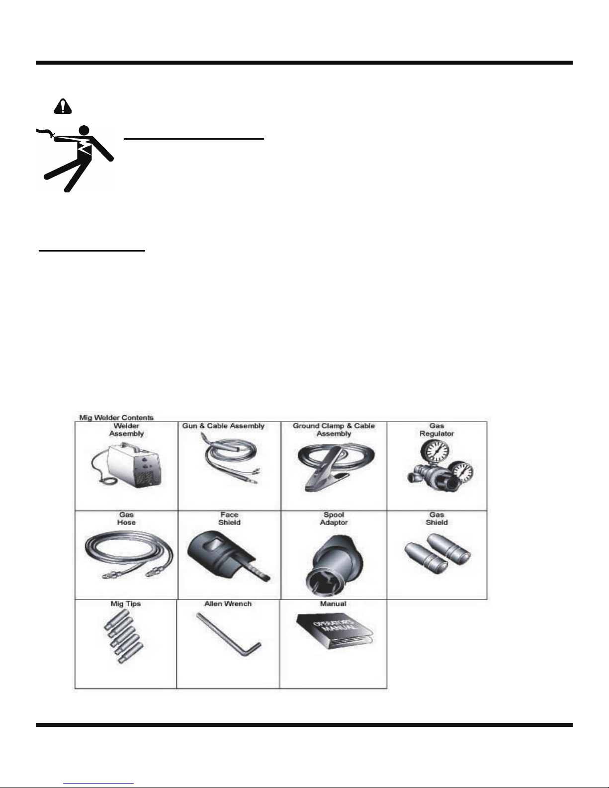
Package Contents
1. WFG Welder
2. Ground Clamp Cable Assembly
3. Gun Cable Assemblies
4. 10# Spool Adapter
5. 5’ Gas Hose
6. Gas regulator
7. Gas Shield Nozzle
8. 5 Contact Tips
9. Hex Wrench
10. Face shield with welding lens
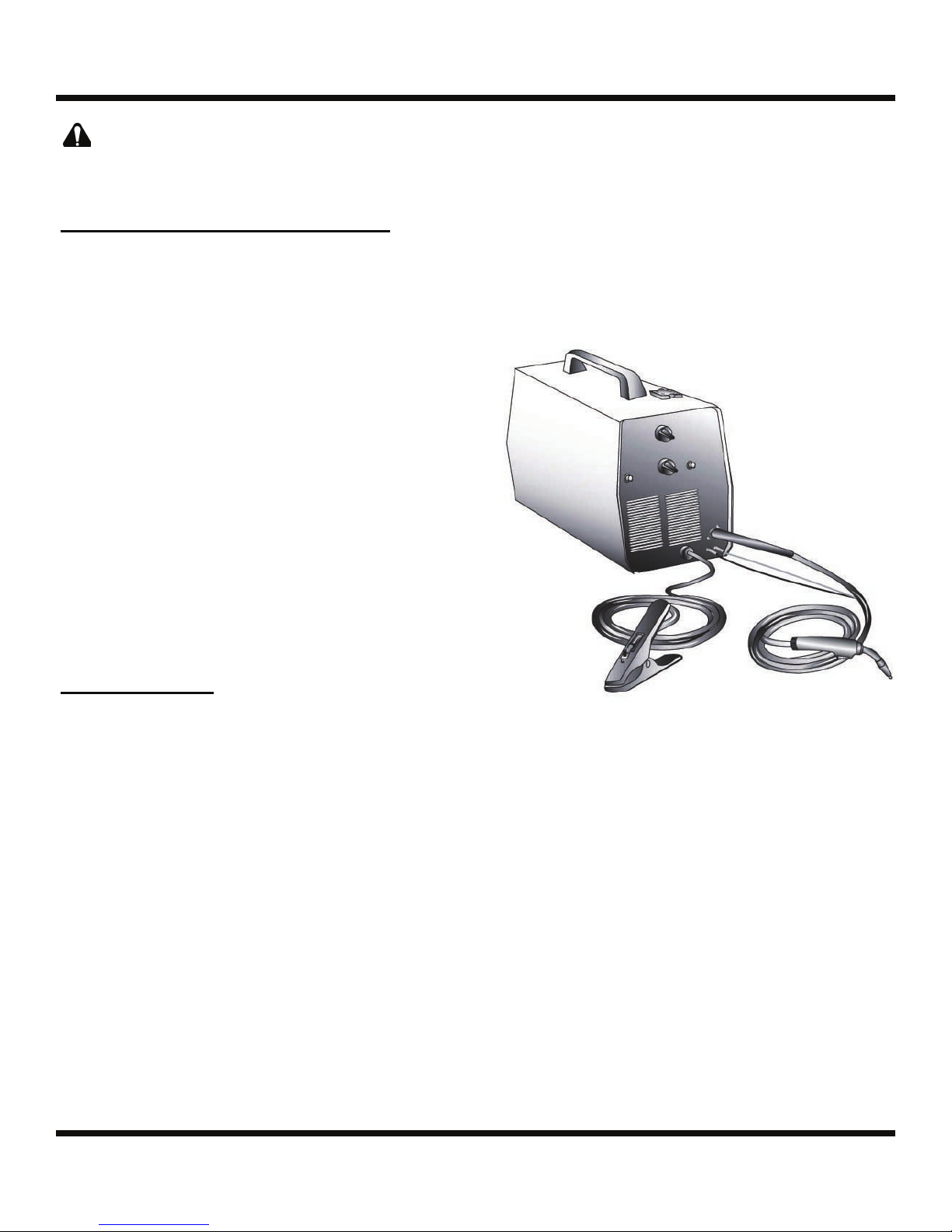
Installation/Setup
Figure 1
KDAR Company 5

Installation/Setup
Selecting A Location
The WFG Welder should be placed where clean cool air can easily flow through the vents in the front of the
unit. Dirt and dust can be drawn into the unit resulting in excessive operating temperatures and shutdowns,
therefore, dirt and dust around the unit should be kept to a minimum.
The WFG Welder should be placed on a stable, level surface suitable to hold the unit’s weight.
These units are not made to be stacked and therefore should never be set on top of one another.
Output Connections
1. Ground Clamp 1/4 turn Connection Port
2. Gun Cable Connection Port
3. Gun Lead Connections
4. Connector Block
5. Positive (+) & Negative (-) Output Terminals
6. Wire Feed Gearbox
7. Thumbscrew
1
3
5
7
2
Figure 2
4
6
6 KDAR Company
Installation/Setup
Warning
Always unplug the welder before connecting or disconnecting the Ground Clamp cable
and/or the Gun Cable.
Ground Clamp & Lead Connection
1. Ground Cable Attachment: The Hot Max Mig
Welders use a convenient 1/4 turn connection for
attaching the ground cable to the unit. Insert the
male end of the ground cable into the female connection port and turn 1/4 turn clockwise.
2. For FCAW (Flux Cored Arc Welding) Only:
The WFG series of welders are delivered set up for
FCAW welding with negative electrode polarity.
The short yellow cable coming out of the connector block is attached to the negative (-) output terminal and the ground lead is connected to the positive (+) terminal.
3. GMAW (Gas Metal Arc Welding) Only: To set
up for GMAW welding with positive electrode polarity, connect the short yellow cable coming from
the connector block to the positive (+) output terminal and the ground lead to the negative (-) output terminal. Make sure all connections are tight.
Gun Installation
1. Insert the male connector on the gun cable into the
gun cable connection port. With the connector all
the way in the connector block tighten the thumbscrew in the connector box.
2. Insert the gun cable terminals to the two gun lead
connectors. It does not matter which terminal goes
in which connector.
Figure 3
KDAR Company 7
 Loading...