

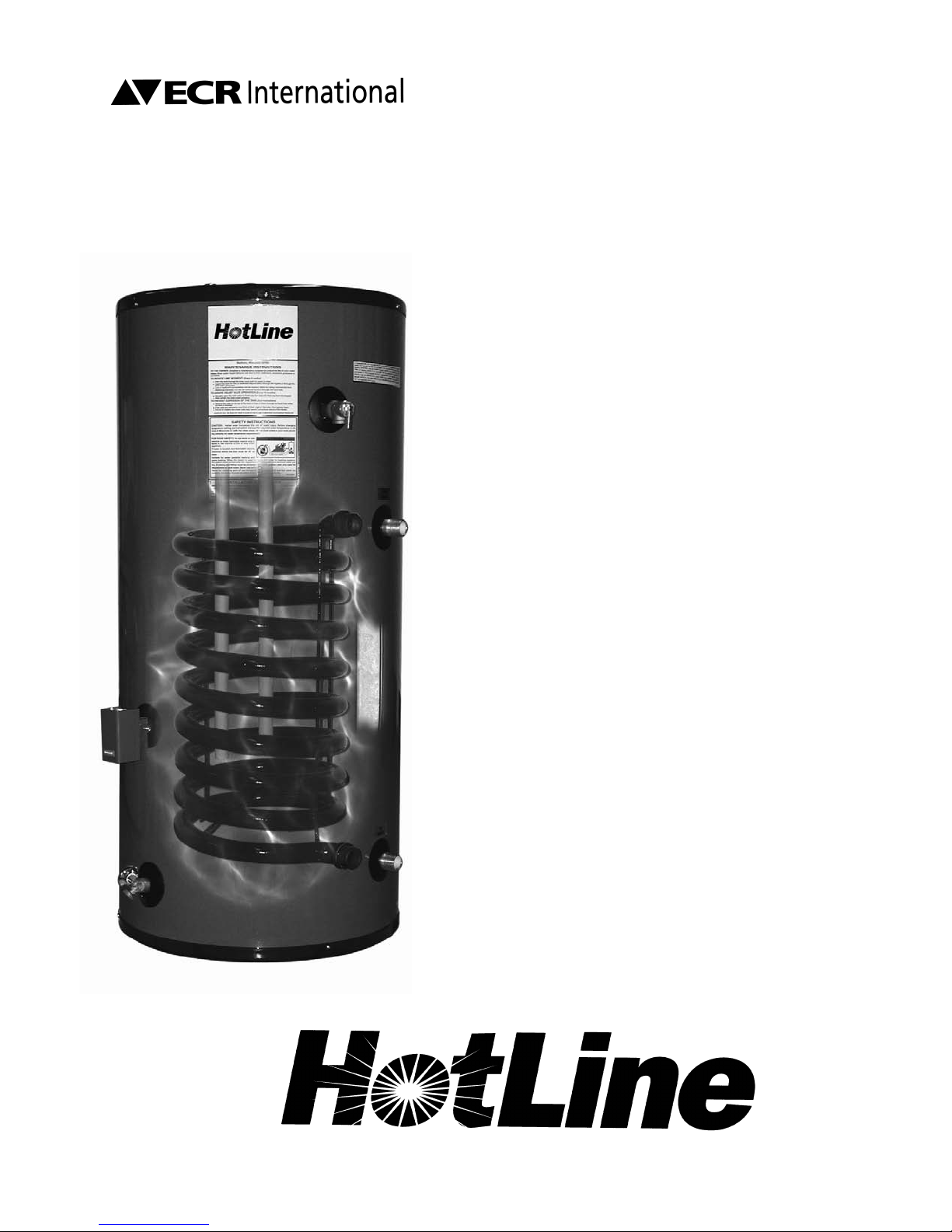
Hotline HL30SK, HL40SK, HL50SK, HL80SK, HL119SK Set-up, Operating & Maintenance Instruction Manual
Page 1
P.O. Box 4729
Utica, NY 13504-4729
www.ecrinternational.com
HOTLINE
INDIRECT
WATER HEATER
MODELS HL30SK, HL40SK, HL50SK,
HL80SK, HL119SK
SET-UP, OPERATING &
MAINTENANCE
INSTRUCTION MANUAL
3 Twice the recovery of a standard gas-fired water
heater
water heater.
and four times the recovery of an electric
3 Counterflow design increases heat transfer by
50% for better temperature mixing.
3 Unique, smooth tube heating coil resists lime
buildup that commonly reduces the life of other indirect water heaters.
3 Steel coil increases heat transfer for faster recov-
ery and the luxury of never running out of hot
water.
3 Coils and tank lining are coated with the finest
porcelain enamel available. Its extra cobalt makes
our heaters highly resistant to damage from aggressive water.
3 Two-inch layer of environmentally-friendly CFC-
free foam insulation enhances efficiency and cuts
fuel bills.
3 Commercial quality at residential prices.
WATER HEATERS MADE IN THE U.S.A.
Page 1
Page 2
To the Installer:
Please attach these instructions
next to the water heater.
To the Consumer:
Please read these and all component
instructions and keep for future reference.
Indirect Coil Tank Water Heater
Instruction Manual
Warranty, Registration Card and Parts List are included.
Homeowner: Please remember to r
eturn the Registration Card!
WARNING
Improper installation, adjustment, alteration,
service or maintenance can cause serious
injury or property damage. Refer to this
manual. For assistance or additional
information, consult a qualified installer or
service agency.
CAUTION
The recommended temperature for normal
residential use is 120°F. The dial on the
aquastat does not always reflect the outcoming water temperature, which could
occasionally exceed 120°F. The variation in outcoming temperature could be based on factors
including but not limited to usage patterns and
type of installation. Test your water at the tap
nearest to the water heater.
WARNING
Hotter water increases the risk of scald injury.
Before adjusting the water temperature setting,
read this instruction manual. Temperatures at
which injury occurs vary with the person’s age
and the length of exposure.
The slower reaction time of children, elderly,
and physically or mentally challenged persons
eases the scalding hazard to them. It is
incr
recommended that lower water temperatures
be used where these exposure hazards exist.
Such households may require a temperature
setting less than 120°F to prevent accidental
contact with hot water.
To lower water temperature use point-of-use
temperature limiting devices.
WARNING
ater heater blankets ar
W
and will void the warranty.
THIS MANUAL HAS BEEN PREPARED
TO ACQUAINT YOU WITH THE INST
OPERA
YOUR WATER HEATER AND TO PROVIDE
TION, AND MAINTENANCE OF
IMPORTANT SAFETY INFORMATION.
e not recommended
TION,
ALLA
INSTALLER RESPONSIBILITIES
Please read all instructions thoroughly before
installing or placing the heater into service.
This unit must be installed by licensed or
authorized installers, or technical personnel
that service water heating equipment. The
heater must be installed in accordance with all
local codes and ordinances.
These instructions are a guide for the correct
installation of the water heater. The
manufacturer will not be liable for damages
caused by failure to comply with the installation
and operating instructions outlined on the
following pages.
CAUTION
The recommended water temperature setting for
normal residential use is 120°F/49°C.
HANDLING
Before uncrating, check for shipping damage.
Report any damage to your carrier. Note damage
on bill of lading or delivery receipt and file a
claim.
FAILURE TO FOLLOW THESE INSTRUCTIONS
OR ALL APPLICABLE BUILDING CODES AND
REGULATIONS VOIDS THE WARRANTY
TER HEA
ON THIS W
Read all instructions thoroughly before
attempting installation or operation of your
water heater. Keep these instructions for future
reference.
Local plumbing and electrical codes must be
followed in the installation of this water
heater. In the absence of a local code use the
UNIFORM PLUMBING CODE and the NFPA
Code. Local codes may supersede instructions
in this installation manual.
These instructions are a guide for the correct
installation of the water heater. The
manufacturer will not be liable for damages
caused by failur
installation and operating instructions
outlined on the following pages.
e to comply with the
A
TER.
#23945 Rev 2 4/06
Page 3

TABLE OF CONTENTS
Section I: Specifications . . . . . . . . . . . . . . . . . . . . . . . . . . . . . . . . . . . . . . . . . . . . . 4
Section II: General Information . . . . . . . . . . . . . . . . . . . . . . . . . . . . . . . . . . . . . . . 6
Section III: Pre-Installation . . . . . . . . . . . . . . . . . . . . . . . . . . . . . . . . . . . . . . . . . . . 8
Section IV: Installation . . . . . . . . . . . . . . . . . . . . . . . . . . . . . . . . . . . . . . . . . . . . . 10
Section V: Maintenance . . . . . . . . . . . . . . . . . . . . . . . . . . . . . . . . . . . . . . . . . . . . 13
Section VI: Troubleshooting. . . . . . . . . . . . . . . . . . . . . . . . . . . . . . . . . . . . . . . . . . 14
Section VII: Parts List . . . . . . . . . . . . . . . . . . . . . . . . . . . . . . . . . . . . . . . . . . . . . . . 15
Section VIII: Warranty . . . . . . . . . . . . . . . . . . . . . . . . . . . . . . . . . . . . . . . . . . . . . . 16
Page 3
Page 4
G
C
old Inlet,
3
/4" NPT
Hot Outlet/
Anode Rod,
3
/4" NPT
A
node
Rod
Aquastat
T
&P Relief
V
alve
F
rom Boiler
Supply, 1" NPT
T
o Boiler
Return, 1"
N
PT
Drain
Valve
F
D
C
E
B
A
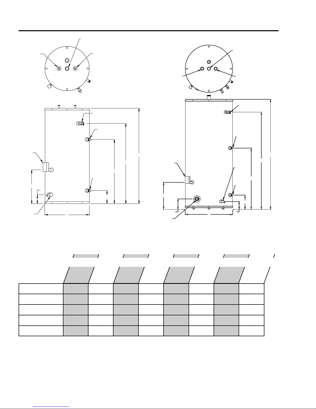
SECTION I: SPECIFICATIONS
G
H
A
E
F
D
C
B
Cold Inlet,
1" NPT
Hot Outlet,
1 1/2" NPT
Anode
Rod
Anode
Rod
T&P Relief
Valve
From Boiler
Supply, 1" NPT
To Boiler
Return,
1"NPT
Drain
Valve
Aquastat
Figure 1: HL30SK, HL40SK, HL50SK
Table 1: Dimensions
Model
HL30SK
HL40SK 22´´ 42 3⁄4´´ 34 3⁄4´´ 31 1⁄2´´ 16 3⁄4´´ 6 1⁄2´´ 4 1⁄2´´ n/a
22´´
A
B
35 3⁄4´´ 27 3⁄4´´ 19 1⁄2´´ 11 3⁄4´´ 6 1⁄2´´ 4 1⁄2´´ n/a
HL50SK 22´´ 48 3⁄4´´ 39 3⁄4´´ 31 1⁄2´´ 16 3⁄4´´ 6 1⁄2´´ 4 1⁄2´´ n/a
HL80SK 24
´´
64 3⁄4´´ 57 1⁄8´´ 33
HL119SK 28´´ 65 1⁄4´´ 57 3⁄4´´ 33 3⁄4´´ 16 1⁄4´´ 8 3⁄4´´ 5´´ 6 1⁄2´´
Foam insulation standard on Indirect models. Pressures, all: Test pressure, 300 PSI Working pressure, 150 PSI
Standard voltage, all: 120V, 60Hz, 1P. T&P valve installed; nipples supplied for top connection.
ARNING:
W
CAUTION: The r
Installation should be in accordance with all national and/or local codes.
ecommended water temperatur
valve or anti-scald valve be installed and used according to the manufacturer's directions to prevent scalding.
Page 4
Figure 2: HL80SK, HL119SK
Dimensions
C
e setting for normal residential use is 120°F. ECR recommends a tempering
D
´´
E
F
19 1⁄4´´ 8´´ 5´´ 5´´
G
H
Page 5
SECTION I: SPECIFICATIONS (cont.)
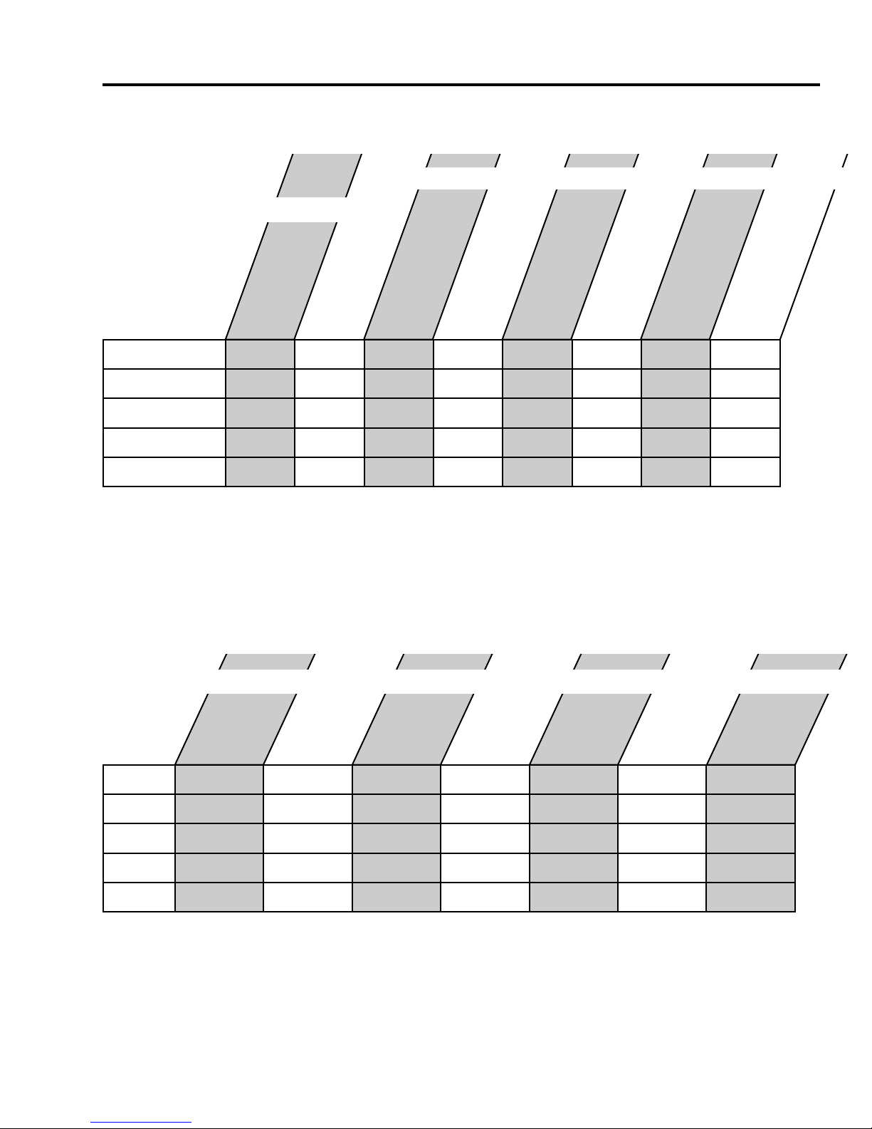
able 2: Capacity & Performance
T
Capacities
Performance
Model
Actual Tank
Volume (gal)
Coil Volume
(gal)
First Hour
Rating (gal)*
Continuous Draw
Rating (GPH)*
First Draw
Rating (gal)*
Minimum Coil
Output (BTU/Hr)**
Standby Loss
Rating (°F/hr)
Heat Source Friction
Loss (ft. w.c.)
HL30SK 30 1.38 110 85 25 55,000 1.3 2.0
HL40SK 38 2.30 153 120 33 77,000 1.1 3.0
HL50SK 45 2.30 160 120 40 77,000 1.0 3.0
HL80SK 75 2.76 200 130 70 83,000 0.9 5.0
HL119SK 110 2.76 232 130 102 83,000 1.2 5.0
NOTES:
* Based on 77°F rise with 58°F potable water inlet temperature at 8 GPM heat source flow rate. Heat source temperature was 180°F.
** Minimum Coil output based on continuous boiler operation over 30 minutes. See Section III for additional considerations.
All data obtained through testing in accordance with GAMA INDIRECT-FIRED WATER HEATER TESTING STANDARD IWH-TS-1_MARCH 2003
Table 3: Performance (cont.)
FIRST HOUR RATING (gal) @ Coil Output (Btu/hr)
°F
Model
HL30SK
180°F
6 GPM*
107 @ 53,000 114 @ 57,000 117 @ 59,000 129 @ 67,000 132 @ 69,000 136 @ 71,000 139 @ 73,000
180°F
10 GPM*
180°F
12 GPM*
200°F
6 GPM*
200°F
8 GPM*
200
10 GPM*
200°F
12 GPM*
HL40SK
HL50SK
HL80SK
HL119SK
NOTES:
First Hour Rating = First Draw + Continuous Draw
* Coil Input (temperatur
All data obtained through testing in accordance with GAMA INDIRECT
141 @ 69,000 165 @ 84,000 177 @ 92,000 171 @ 88,000 183 @ 96,000 195 @ 104,000 207 @ 111,000
148 @ 69,000 172 @ 84,000 184 @ 92,000 178 @ 88,000 190 @ 96,000 202 @ 104,000 214 @ 111,000
188 @ 76,000 212 @ 91,000 224 @ 98,000 221 @ 97,000 233 @ 104,000 245 @ 112,000 257 @ 119,000
220 @ 76,000 244 @ 91,000 256 @ 98,000 253 @ 97,000 265 @ 104,000 277 @ 112,000 289 @ 119,000
e, flow rate). Ratings based on 77°F rise with 58°F inlet potable water.
-FIRED W
TER HEATER TESTING STANDARD IWH-TS-1_MARCH 2003
A
Page 5
Page 6
SECTION II: GENERAL INFORMATION
LOCATION
The indirect coil tank water heater should be located in a central location to the piping
system, as close as practical to the boiler and in an area not subject to freezing temperatures.
eave sufficient space for servicing and maintaining the heater.
L
Note: Long heating supply runs can lengthen recovery times.
WATER TREATMENT/FILTRATION
In areas where poor water conditions are suspected (i.e. lime, iron, and other minerals), it is
essential that the water be tested and appropriate action taken to prevent damage to the
indirect heater and ensure the quality of the water.
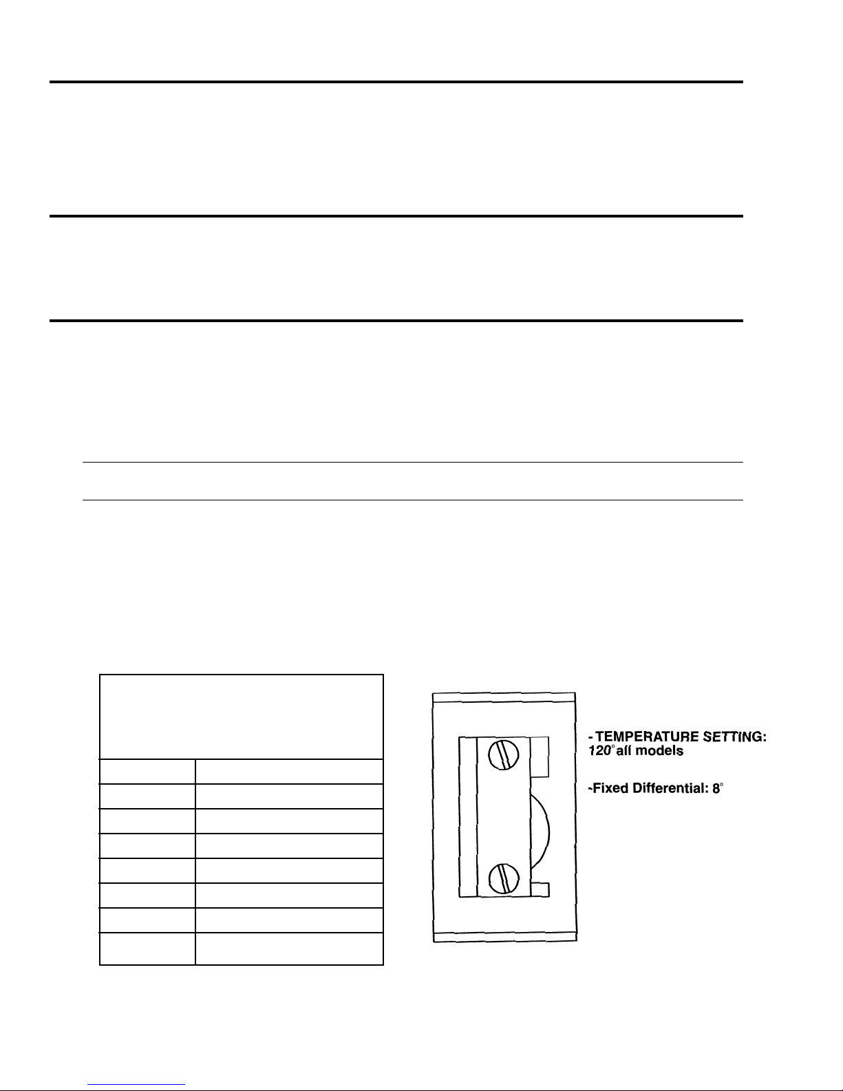
TEMPERATURE CONTROL
Water temperature from the heat source / boiler to the indirect coil tank water heater is
controlled by an immersion aquastat. This control operates the circulator, and provides
limited control for domestic hot water temperature. The proper temperature setting for
domestic hot water use is 120°F/49°C. If hotter water is required a tempering device or
anti-scald device must be installed at the domestic hot water outlet of the heater or at the
point of use.
CAUTION: Hot water in excess of 120°F
can cause scalding!
HotLine recommends a tempering valve or anti-scald valve be installed and used according
to the manufacturer’s directions to prevent scalding. Many state and local codes now require
installation of these devices. The tempering valve or anti-scald valve will ensure potable
water temperatures at the desired set point with a higher degree of accuracy.
IMMERSION CONTROL
HL40SK •HL50SK
•
HL119SK
•
APPROXIMATE
TEMPERATURE/TIME
RELATIONSHIPS TO
SCALDING
120°F More than 5 minutes
1
125°F 1
130°F About 30 seconds
135°F About 10 seconds
140°F Less than 5 seconds
⁄2 to 2 minutes
HL30SK
HL80SK
145°F Less than 3 seconds
1
150°F About 1
155°F About 1 second
Page 6
⁄2 seconds
Page 7

SECTION II: GENERAL INFORMATION (cont.)
ANODE RODS
The anode rod is used as a sacrificial element within the volume of the storage tank. The
purpose of the magnesium anode rod is to protect the inside of the tank against corrosion.
node rods should be inspected twice in the first year and at least yearly once a time interval
A
for inspection has been developed. Water conditions can influence the consumption rate of
he anode rods. Please see the Maintenance section of this manual for instructions on how to
t
change the anode rods in your Hot Line water heater.
CAUTION: Hydrogen gas is produced in a hot water system served by this heater that has not been used for
a long period of time (2 weeks or more). Hydrogen gas is extremely flammable. To reduce the risk of injury
under these conditions, it is recommended that the hot water faucet be opened for several minutes at the
kitchen sink before using any electrical appliance connected to the hot water system. When hydrogen is
present, there will probably be an unusual sound such as air escaping through the pipe as the water begins to
flow. There should be no smoking or open flame near the faucet at the time it is open (UL 174).
TEMPERAURE AND PRESSURE RELIEF VALUE (T&P)
The T&P valve is factory installed. A discharge drain tube must be installed (responsibility of
the installer) and shall terminate plain, not threaded, 6 inches above the floor drain. The
drain tube material must be approved for temperatures of 120°F or greater, and a pressure of
150 PSI or greater.
BACK-FLOW PREVENTOR (CLOSED LOOP SYSTEM)
Some local municipal codes and ordinances require the use of these devices on potable
(domestic) water lines. Where back-flow preventors are required, it will be necessary to
install a thermal expansion tank (designed for used with potable water) in order to prevent
pressure build up in the indirect heater and associated piping, which could cause the T&P
valve to discharge. Follow the expansion tank manufacturer’s recommendations when
selecting a tank for your hot water system.
Note: Working pressure of the water heater is 150 PSI. Do not exceed 150 PSI.
Page 7
Page 8
SECTION III: PRE-INSTALLATION
BOILER AND CIRCULATOR SIZING
The ratings published in this manual for your HotLine Indirect Coil Tank Water Heater can
be obtained through proper selection of boiler output and circulator capacity. As noted, the
atings in Table 2 are based on a 77°F rise with 58°F potable water inlet temperature at a
r
circulator pump flow rate of 8 GPM. The boiler was set at 180°F. See Table 3 for additional
irst hour ratings at pump flow rates of 6, 8, 10 and 12 GPM with 180°F and 200°F boiler
f
water.
To determine the appropriate circulator for your system, follow these three steps:
1) Calculate the pressure drop of all straight pipe and fittings on the supply and return at the
desired flow rate.
2) Add the pressure drop from Step 1 to the pressure drop through the indirect coil tank
water heater coil (see Table 2 for friction loss) to obtain a total pressure drop.
3) Select a circulator pump that will provide adequate flow at the total pressure drop.
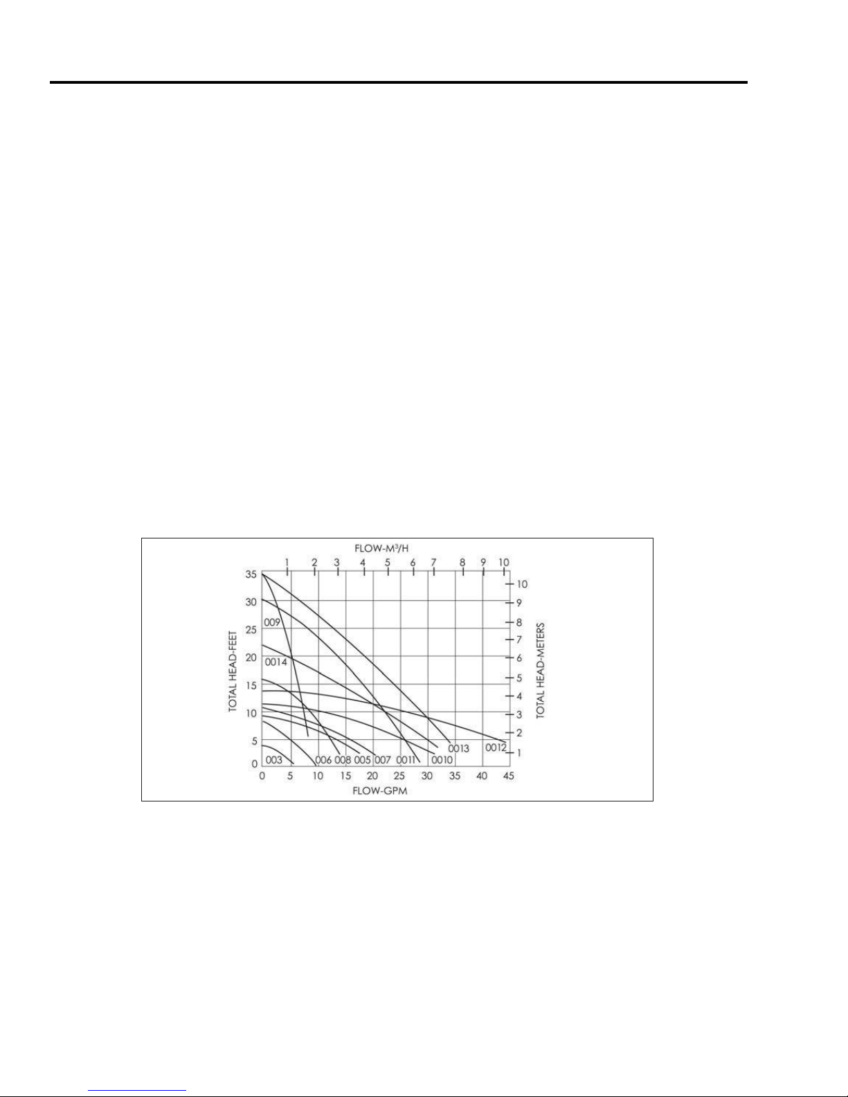
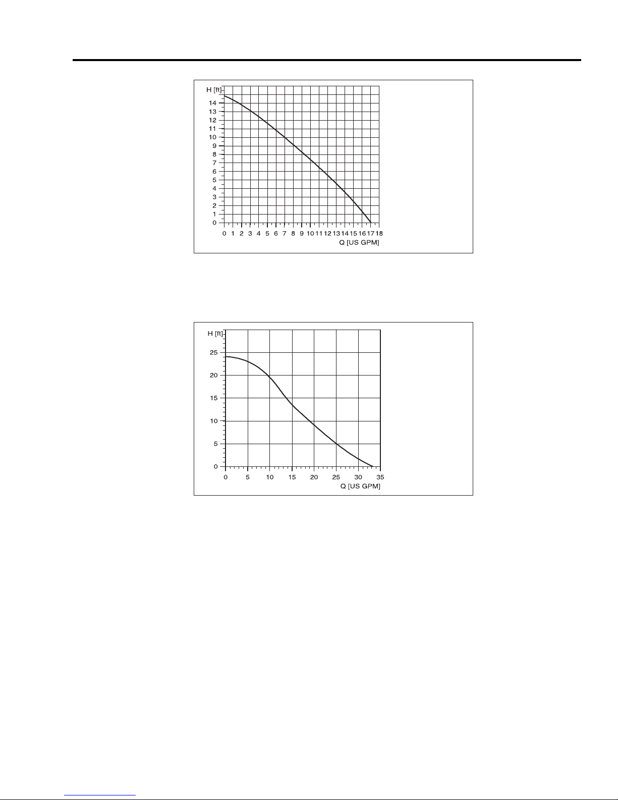
A pump performance curve should accompany every circulator pump. Figures 3-5 contain
performance curves for Taco and Grundfos circulator pumps, recommended by HotLine.
Figur
Page 8
e 3: Taco 00 Series performance curves
Page 9
UP 15-42F/FR
C
losed Systems, 60 Hz
UP 26-64F
Closed Systems, 60 Hz
SECTION III: PRE-INSTALLATION (cont.)
Figure 4: GRUNDFOS UP 15-42F performance curve
Note: Zone valves on the heat source supply to the indirect heater are not recommended
and will drastically reduce performance.
System performance can also vary based on the heating capacity of the boiler. If the
minimum coil output (assume coil output = boiler output) listed in Tables 2 and 3 is not met,
the output (first hour rating) of the water heater will not be met at the selected flow rate.
To approximate the reduction in first hour rating as a result of low boiler capacity, use the
following formula:
New first hour rating = (First hour rating) * (Actual boiler output)/(Minimum coil output)
For example, the first hour rating of a 50SK at a 77°F rise with an 8 GPM heat source flow rate
using a boiler having a DOE heating capacity (output) of 60,000 BTU/Hr would be:
New first hour rating = (160 gal) * (60,000 BTU/Hr)/(77,000 BTU/Hr) = 125 gal
e 5:
Figur
GRUNDFOS UP 26-64F performance curve
Page 9
Page 10
B
OILER
S
UPPLY
SYSTEM
DOMESTIC
3/4"
HOT OUT
INDIRECT
WATE R HEATER
BOILER
TO
BOILER
FROM
COLD
INLET
3/4"
VALVE
CHECK
PUMP
CIRCULATOR
RETURN
S
YSTEM
BOILER
BOILER
1" NPT
1" NPT
BOILER
SYSTEM
SUPPLY
CIRCULATOR
PUMP
BOILER
SYSTEM
RETURN
BOILER
COLD
1"
INLET
WATE R HEATER
INDIRECT
HOT OUT
DOMESTIC
1 1/2"
BOILER
FROM
TO
BOILER
CHECK
VALVE
BOILER
SUPPLY
SYSTEM
DOMESTIC
3/4"
H
OT OUT
INDIRECT
WATE R HEATER
B
OILER
T
O
BOILER
F
ROM
COLD
INLET
3/4"
VALVE
CHECK
PUMP
CIRCULATOR
RETURN
SYSTEM
BOILER
BOILER
1" NPT
1
" NPT
1" NPT
1" NPT
SECTION IV: INSTALLATION
WATER CONNECTIONS
All piping between the boiler and the indirect heater should be new copper with a
minimum size of 3/4” ID for models HL30SK, HL40SK, and HL50SK. Use 1” minimum copper
or models HL80SK and HL119SK. Elbows should be minimized. A flow check valve must be
f
installed on the return line.
All piping to the inlet (cold) and outlet (hot) domestic water connections should be new
copper with a minimum size of 1/2” ID for models HL30SK, HL40SK, and HL50SK. Use 3/4”
ID minimum for models HL80SK and HL119SK.
All piping should conform to local codes and ordinances. At a minimum, refer to IHLR 84
code if local codes are not in place. It is recommended that all piping be adequately
insulated with approved material to ensure minimum heat loss. If a re-circulation line is
used for domestic water, be certain that all lines are well insulated and the circulator is
temperature controlled. Install isolation valves to permit proper servicing. It is also
recommended to install a union on the domestic outlet to facilitate replacement of the hot
outlet / anode nipple on models HL30SK, HL40SK, and HL50SK.
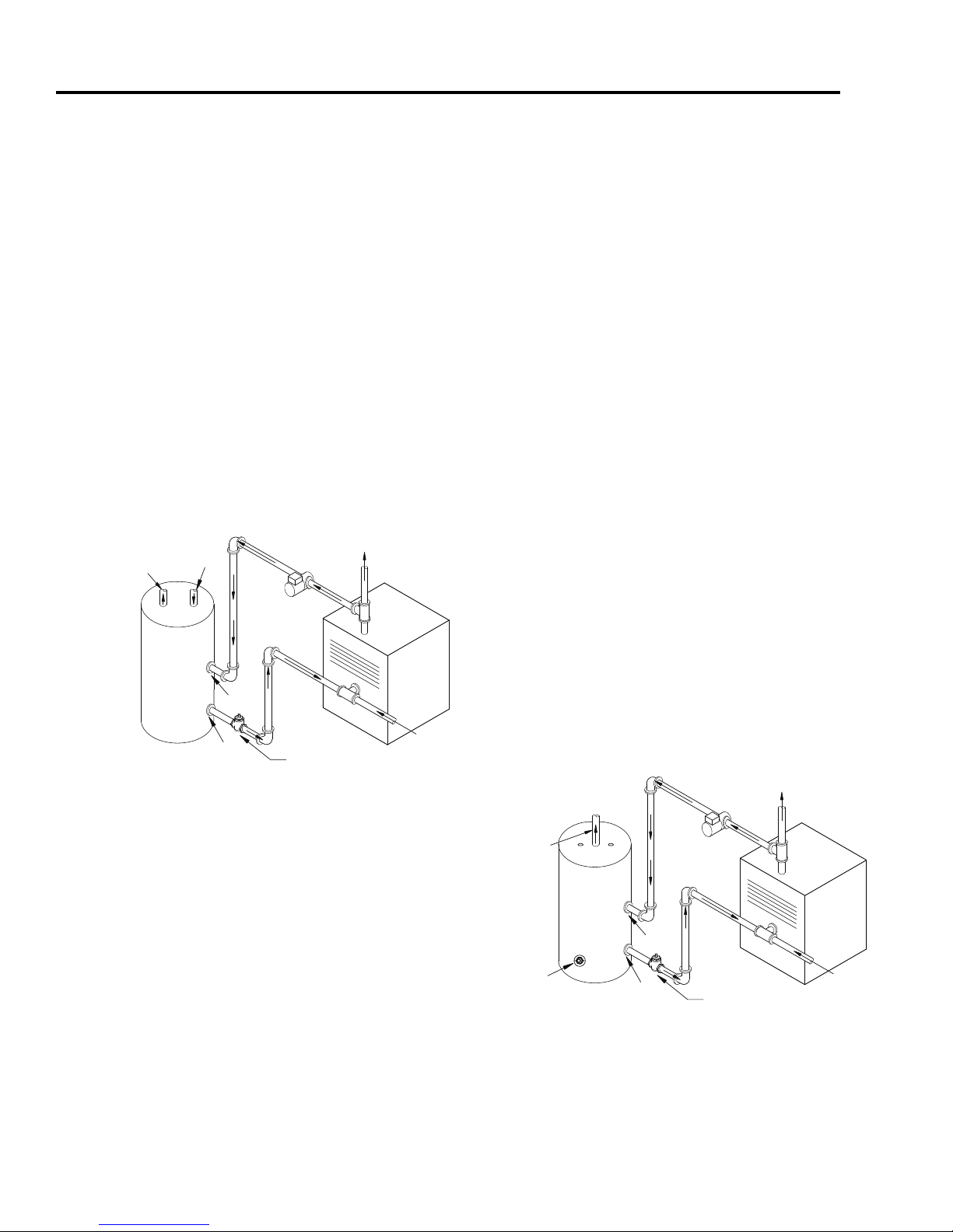
See Figures 6 and 7 for proper water connection installation.
HL
Note: Indirect may be connected to a steam
boiler pr
Figure 6: HL30SK, HL40SK, HL50SK
ovided that all piping to and fr
the boiler are below the water line of the boiler.
Boiler must also be protected by a low water
cut of
Page 10
f safety device.
water connections
om
Figure 7: HL80SK, HL119SK water connections
Page 11
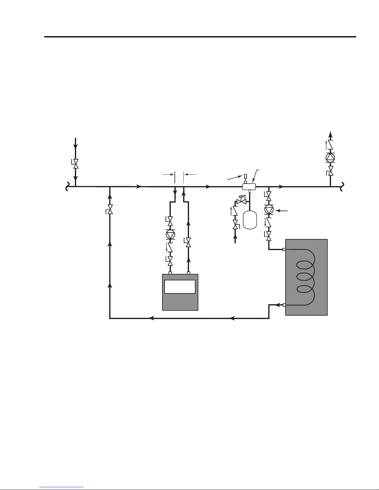
SECTION IV: INSTALLATION (cont.)
CHECK
VALVES
ZONE
CIRCULATO RS
ISOLATI ON
VALVES
ADDITIONAL
ZONES
INDIRECT
CIRCULATOR
INDIRECT WATER
HEATER
TO
HEATING
ZONE
AIR
SEPARATOR
AIR VENT
EXPANSION
TANK
COLD
WATER
INLET
BOILER
CIRCULATOR
LESS THAN (4)
PIPE DIAMETERS
BOILER
F
ROM
HEATING
ZONE
ISOLATI ON
VALVES
A
DDITIONAL
ZONES
ee Figure 8 for piping your HotLine Indirect Coil Tank Water Heater to a low-mass boiler
S
(diagram recommended by boiler manufacturer).
Figure 8: HotLine Indirect with Low-Mass Boiler
Page 11
Page 12
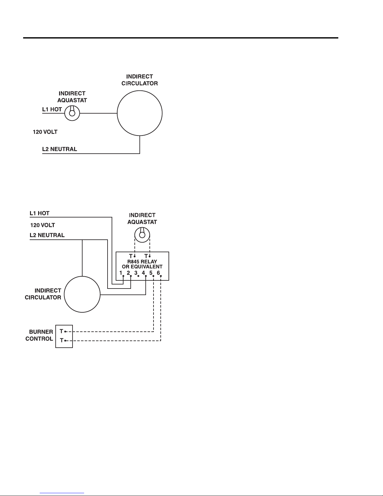
SECTION IV: INSTALLATION (cont.)
ELECTRICAL CONNECTIONS
Figure 9: Boiler Maintaining 180°F
Figures 9 and 10 are general wiring diagrams.
For a maintaining temperature boiler, Figure 9
should closely match your system. For cold start
boilers your wiring may resemble Figure 10, but
will vary depending on the boiler type and
controls or relays used. It is not possible to list all
wiring variations here. When connecting to a cold
start boiler, always remember that in principle an
indirect coil tank heater operates as another
heating zone. The difference is when the indirect
calls for heat, the indirect coil tank heater
circulator must start rather than opening a zone
valve; the system circulator stays off; and the
boiler must light to reach high limit.
WIRING NOTES:
1. Dashed lines indicate low voltage (24 VAC)
Figure 10: Cold Start Boiler
2. Use jumper wire between terminals #1 and #3
on R845 relay
THERMOSTAT SPECIFICATIONS:
Thermostats can operate at low or line voltages.
24 volt N/A
120 volt 8 amp
240 volt 5 amp
This equipment must be properly grounded to
prevent a potential shock hazard, and to reduce
deterioration of the anode due to electrolysis.
Refer to local electrical codes and ordinances.
Page 12
Page 13

SECTION V: MAINTENANCE
WATER PIPING
On an annual basis, all piping should be checked for leakage at joints, shut-off valves, and
unions.
T&P RELIEF VALVE
On an annual basis, the temperature and pressure relief valve should be checked for proper
operation. First, attach a drain line to the valve to direct the water discharge to an open
drain. This is very important because the temperature of the discharge could be very hot.
Second, lift the lever at the end of the valve several times. The valve should operate freely
and return to its original position properly. If water does not flow out of the valve, remove
and inspect for corrosion or obstructions. Replace with a new valve if necessary. Do not
repair the faulty valve as this may cause improper operation.
ANODE RODS
Anode rods should be inspected twice in the first year and at least yearly once a time interval
for inspection has been developed. It is recommended to check the rod(s) six months after
the heater is installed. If the anode rod had reduced in size by two-thirds of its original
diameter of 3/4” or shows signs of pitting, it is time for replacement. Take the following
steps when changing the anode rod(s):
1. Shut off water supply.
2. Open any faucet to relieve tank pressure.
3. Remove caps on water heater top; push insulation aside.
4. Use a 1 1/16” six-sided socket wrench and a breaker bar. Snap hard to break the anode
rod seal.
5. Remove rod(s) and replace with new rod(s).
6. Turn water supply back on and leave faucet open until air is out of line.
7. Turn faucet off and check that new rod(s) doesn’t leak.
8. Snap caps back into place.
FLUSH THE TANK
T
he indirect coil tank water heater is glass lined. Elements in the water such as lime, iron
and other minerals may accumulate in the heater. It is recommended that the tank be
drained and flushed thoroughly once a year to prevent buildup in the tank.
Page 13
Page 14
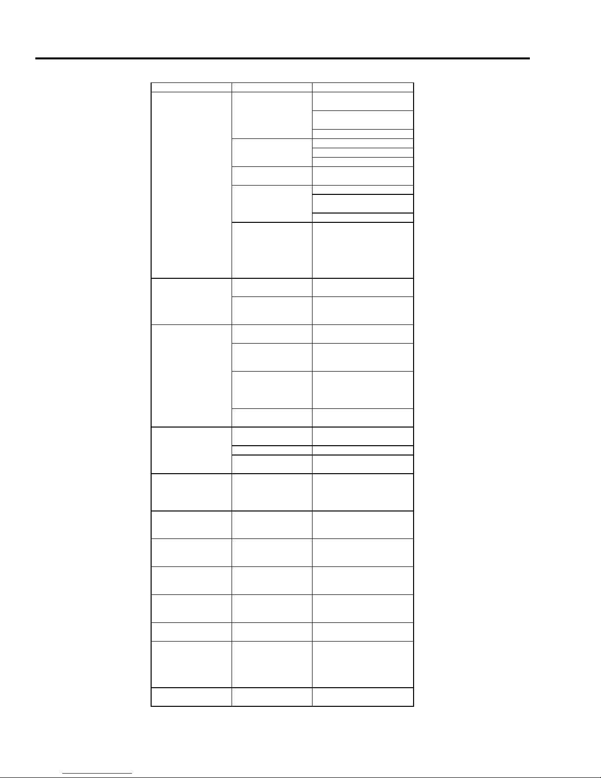
C
irculator does not
operate
Check aquastat setting
PROBLEM CAUSE SOLUTION
Boiler does not
operate
Refer to boiler installation
instructions
Check main service switch
C
heck fused disconnect
Peak use of hot water
is greater than tank
storage capacity
Determine peak usage,
compare to tank capacity,
and add additional storage
(storage tank) if necessary
Improper aquastat
setting
Turn tank aquastat to safe
temperature setting
Electrical problem
(relay, wiring, etc.)
Check fuse and replace
Check circuit breaker and
reset (if applicable)
Check power supply
Aquastat set too low Raise aquastat setting to
safe level. See Section III
Undersized boiler with
no priority to
domestic hot water
Rewire for priority
No hot water at faucet
Water at faucet too
hot
Aquastat set too high Lower aquastat setting to
safe level
T
empering valve not
properly set or
defective
C
heck manufacturers
instructions
S
cale build-up If boiler, circulator, and tank
are operating satisfactorily,
coil may have scale coating.
See Section VI for tank
flushing procedure.
Check power supply
R
eplace as necessary
Faulty tank aquastat Replace aquastat
Boiler cycles more
than 5 times per day
during hotest months
Excessive demand Reduce demand or consider
larger tank
Faulty aquastat Replace aquastat
Boiler high limit set
too low
Increase boiler high limit
setting
Insufficient hot water
Rust staining; bad
taste and odor in
water
Iron/minerals in water
supply
Filtration
Scale, hard white
particles from faucets,
popping sound from
tank
Lime, water hardness
above 7 grains120ppm
Water treatment; softener;
etc.
Rotten egg odor Hydrogen Sulfide Flush tank with chlorine
solution and install
alumninum anode rod(s)
Air from hot water
fixture
Electrolysis or air
introduced by water
supply
Properly ground heater &
replace anode rod(s). Check
well pump system.
Reduction in recovery Dip tube broken or
compromised by high
chlorine in water
Replace dip tube
Inlet/Outlet fitting
corrosion
Galvanic corrosion of
dissimilar metals
Install dielectric unions
T&P gushing water Excessive water temp.
(above 210 °F)
Adjust or replace aquastat
and T&P valve
T&P Valve dripping
water
Excessive water
pressure (above 150
psi)
Check incoming water
supply pressure; closed loop
system (System Plus)
requires expansion tank
SECTION VI: TROUBLESHOOTING
Page 14
Page 15
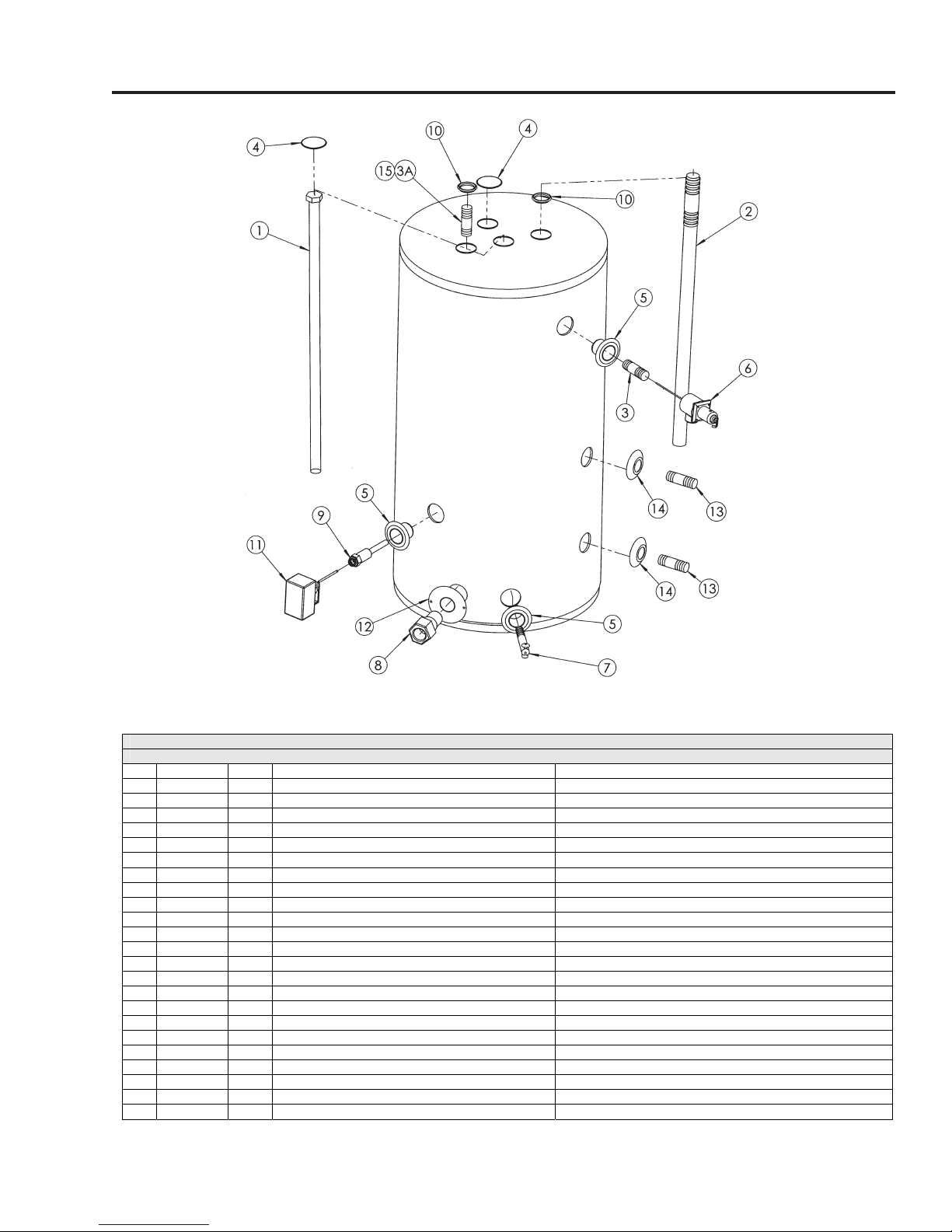
Page 15
SECTION VII: PARTS LIST
INDIRECT COIL TANK WATER HEATERS
HL30SK, HL40SK, HL50SK, HL80SK, HL119SK
# Item # Qty Description Applicable Models
1
ST00301 1 Magnesium Anode Rod 3/4" x 30" HL30SK, HL40SK, HL50SK
1
ST00701 2 Magnesium Anode Rod 3/4" x 36" HL80SK
1
ST00901 2 Magnesium Anode Rods 3/4" x 40" HL119SK
2
ST00401 1 Dip Tube 3/4 x 3 x 33" HL30SK
2
ST00801 1 Dip Tube 3/4 x 3 x 44" HL50SK
2
ST01301 1 Dip Tube 3/4 x 3 x 38" HL40SK
3
Nipple 3/4 x 3", Hot Out or T&P HL80SK, HL119SK
3A
Nipple, 1 1/2" HL80SK, HL119SK
4
Cap, Magnesium Anode Rod HL30SK, HL40SK, HL50SK, (3) HL80SK, (3) HL119SK
5
Leak Detector Fitting HL30SK, HL40SK
5
Leak Detector Fitting HL50SK, HL80SK, HL119SK
6
ST00601 1 T&P Relief Valve 3/4" LL100XL HL30SK, HL40SK, HL50SK
6
ST01001 1 T&P Relief Valve 140X-5 (use with 15370) HL80SK, HL119SK
7
Drain Valve 3/4 x 2 1/4" HL30SK, HL40SK, HL50SK, HL80SK, HL119SK
8
Cold Water Inlet Bushing 1" HL80SK, HL119SK
9
Well - PNW-3SE 1.5PL (use with 21575) HL30SK, HL40SK, HL50SK, HL80SK, HL119SK
10
Ring, Snap-in HL30SK, HL40SK, HL50SK
11
ST01101 1 Aquastat L4080B-1352 HL30SK, HL40SK, HL50SK, HL80SK, HL119SK
12
Steel Ring 5-3/8 HL80SK, HL119SK
13
Nipple, 1 x 3 , plastic lined HL30SK, HL40SK, HL50SK, HL80SK, HL119SK
14
Finish Ring, plastic HL30SK, HL40SK, HL50SK, HL80SK, HL119SK
15
Nipple 3/4 x 3", Hot Out with Anode HL30SK, HL40SK, HL50SK
Page 16

SECTION VIII: WARRANTY
LIMITED LIFETIME WARRANTY
GENERAL CONDITIONS
Hot Line Water Heaters, ECR International, warrants that the
ot Line tank shall be free of defects in material and workman-
H
ship during normal use and service for as long as the original
residential purchaser owns the home in which the unit was originally installed. For the purposes of this Limited Warranty, residential purchaser is defined as the owner of a single family
home in which the purchaser resides on a permanent basis.
If at the time of a request for warranty the original residential
purchaser can not provide a copy of the original sales receipt,
deed, or equivalent document, then the warranty period for the
Hot Line shall be seven (7) years from the date of manufacture
of the unit. The Limited Warranty on the tank shall be reduced
to a period of three (3) years if the purchaser is a business, partnership or corporation, or if the water heater is used for a commercial or multi-family residential property application.
Should a leak develop within this Limited Warranty period due
to defective materials or workmanship and such leak having
been verified by an authorized company representative, ECR
International will repair the unit or furnish a replacement Hot
Line heater or the nearest comparable model available at the
time of replacement.
ECR International shall not be liable for any water damage
arising directly or indirectly from any defect in the water
heater or component part(s) or from the use thereof or any
service call not involving malfunction or defects in materials or
workmanship.
THIS WARRANTY IS VOID AND SHALL NOT APPLY IF:
1) The unit is not correctly installed according to the installation instructions provided with the unit.
2) The residential indirect-fired water heater is installed in
buildings other than one or two family dwelling units, unless
the buildings contain individual indirect-fir
for each dwelling unit.
3) The indirect-fired water heater is operated at water temperatur
mor
es of more than 125 degrees F. and water pressure of
e than 150 PSI.
ed water heaters
7) ECR International Hot Line is installed outside of the
nited States or Canada.
U
8) ECR International Hot Line is repaired or altered without
prior written approval of ECR International and this service adversely affects the product’s reliability.
9) The malfunction or repairs result from the use of ECR In-
ternational Hot Line for purposes other than that for which it
was designed or any malfuction resulting from flood, fire,
wind or lightning.
ECR International will provide, under the Limited Warranty,
only a replacement water heater, repairs, or parts for defective units. The Limited Warranty does not cover any component of ECR International Hot Line that has to be replaced
during the warranty period as a result of reasonable wear
and tear, labor costs, shipping charges, delivery expenses,
nor administrative fees incurred by the customer in removing
or reinstalling the Hot Line.
In no event shall ECR International be liable for incidental or
consequential damages. Some states do not allow the exclusion
or limitation of incidental or consequential damages, so the
above limitation or exclusion may not apply to you.
In order to gain coverage under this Limited Lifetime Warranty, the consumer is required to fill out and mail the Limited
Warranty registration card provided with the unit by registered mail within 30 days of purchase.
To submit a warranty claim, contact the dealer who sold the
Hot Line covered by this Limited Warranty. If the dealer cannot be located, contact ECR International at the address
shown below. Whenever any inquiry or service request is
made, please include the Hot Line model number, serial number, date of installation, and dealer’s name.
No warranty, express or implied, other than the foregoing Limited Warranty is authorized by ECR International and no rep-
esentative of ECR Inter
r
component has the authority to amend, extend, modify, enlarge
or contract the foregoing Limited Warranty and the disclaimers
of the Limited W
national or of the manufactur
ranty in any manner whatsoever.
ar
er of any
4) The failur
gent operation, accident, abuse (including freezing), misuse,
unauthorized alteration, impr
excessive pressur
similar cause.
5) The failure or malfunction results from failure to keep the
unit full of potable water, free to circulate at all times; or fail-
e due to water sediment or scale deposits.
ur
6) The original serial number of the water heater cannot
readily be determined.
Page 16
e or malfunction r
e or leaks at water connections or any other
esults fr
oper repair or maintenance,
om impr
oper or negli
-
WATER HEATERS MADE IN THE U.S.A.
ECR International
P.O. Box 4729•Utica, NY 13504-4729
www.ecrinternational.com
 Loading...