

Page 1
1110 66-70 B-Body, 70-14 E-Body
P/N : 1110
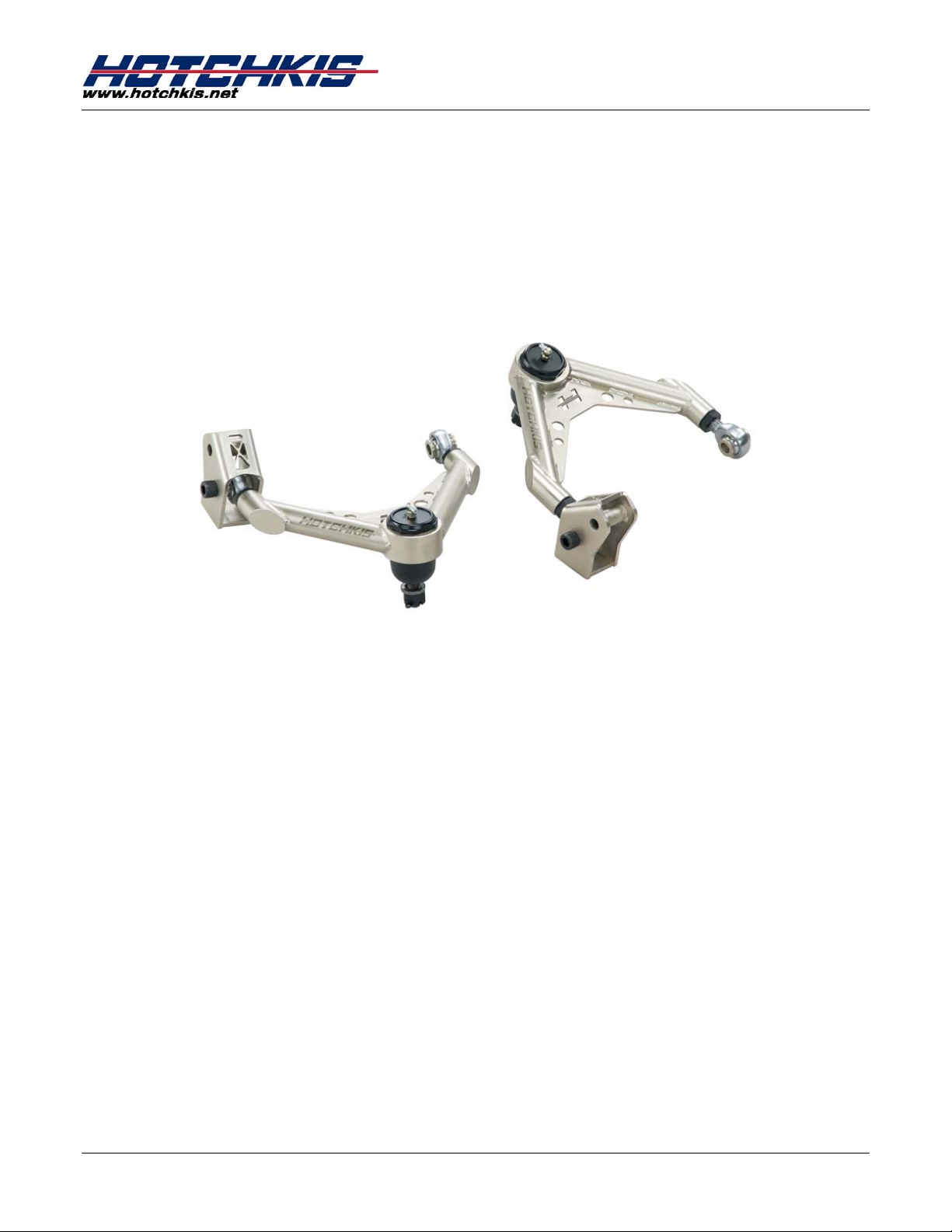
Tubular Upper A-Arm
1966-1970 Chrysler B-Body, Charger,
Super Bee, Road Runner, GTX
1970-1974 Chrysler E-Body, Cuda, Challenger
Thank you for your purchase from our new line of B & E-Body parts.
Please call us at (877) 4NO - ROLL if you have any questions
regarding the service or installation of your Hotchkis products.
Hotchkis Performance LLC. 1
Page 2
Before You Start:
Please read the entire manual before starting. Most pictures shown are of the
driver side a-arm. Please perform the same procedure for the passenger side.
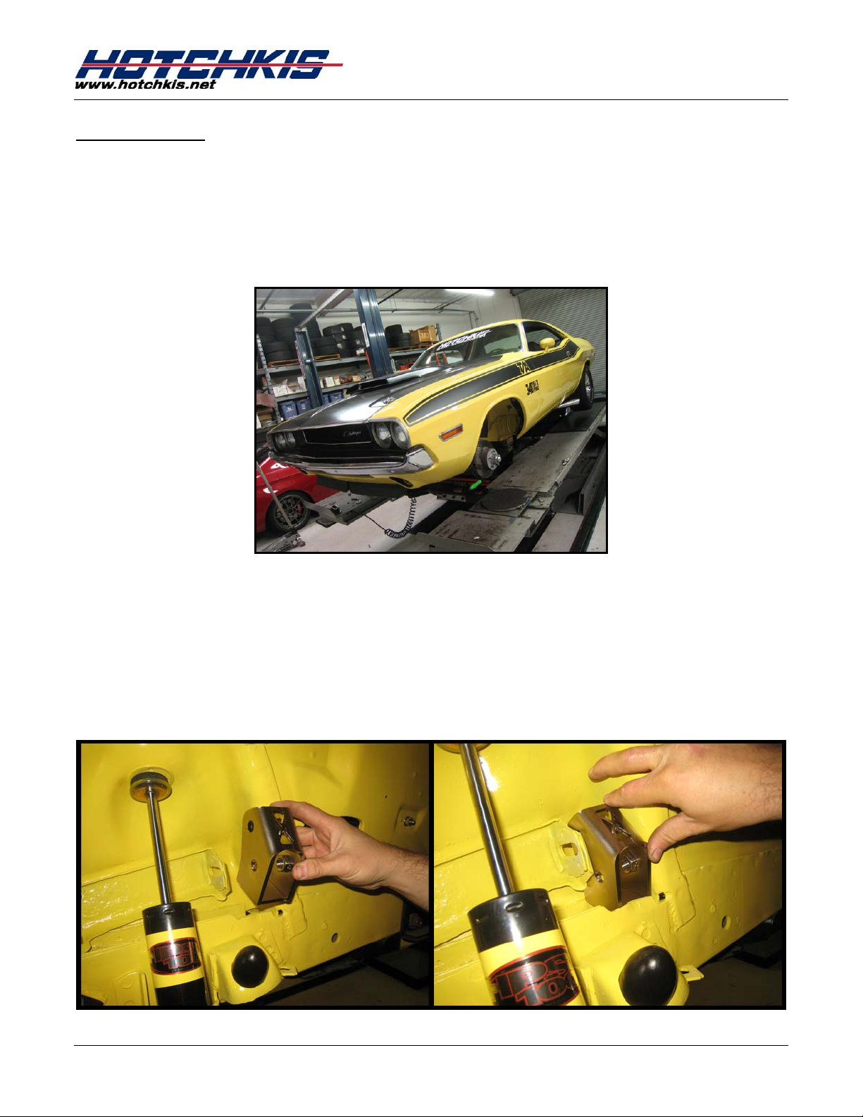
1. Raise Vehicle
Raise the vehicle and put it up on jack stands. You may also use a 2-post or 4post lift.
1110 66-70 B-Body, 70-14 E-Body
2. Remove Stock Arms
Remove the front wheels and uninstall the stock upper A-Arms.
3. A-Arm Relocater
Place the A-Arm Relocator into place as shown below. The Relocators are only
installed on the forward mounting point. (NOTE: Picture is showing Passenger
side)
Hotchkis Performance LLC. 2
Page 3
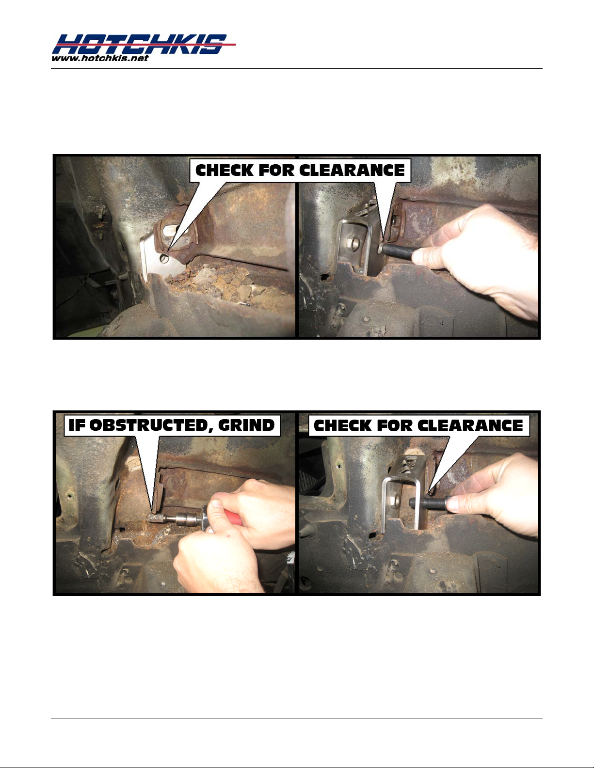
4. Check for Bolt Clearance
In some instances, we seen clearance issues for the Relocator bolt. Check to
see if the hole that is used to connect the A-Arm is clear. (NOTE: Pictures below
shows the Driver side)
5. Grind if Necessary
If anything is in the way, grind it down and recheck clearance. Repeat until bolt
fits.
1110 66-70 B-Body, 70-14 E-Body
Hotchkis Performance LLC. 3
Page 4
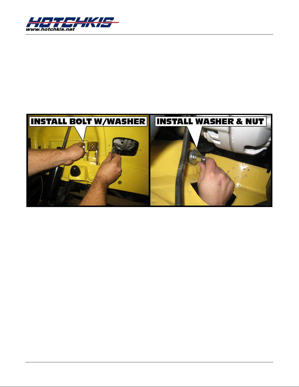
6. Install A-Arm Relocators
Slide the stock camber bolt w/washer through the top hole of the A-Arm
Relocator. The other end will end up inside the engine bay. Install the washer
and nut snugly, but do not fully tighten. You will need to induce some preload
to position the Relocator properly. You can do this by rotating the camber bolt
clock wise until you feel resistance. The Relocator should position itself snugly
onto the frame. Fully tighten the camber bolt by tightening the nut side keeping
the bolt static.
1110 66-70 B-Body, 70-14 E-Body
Hotchkis Performance LLC. 4
Page 5
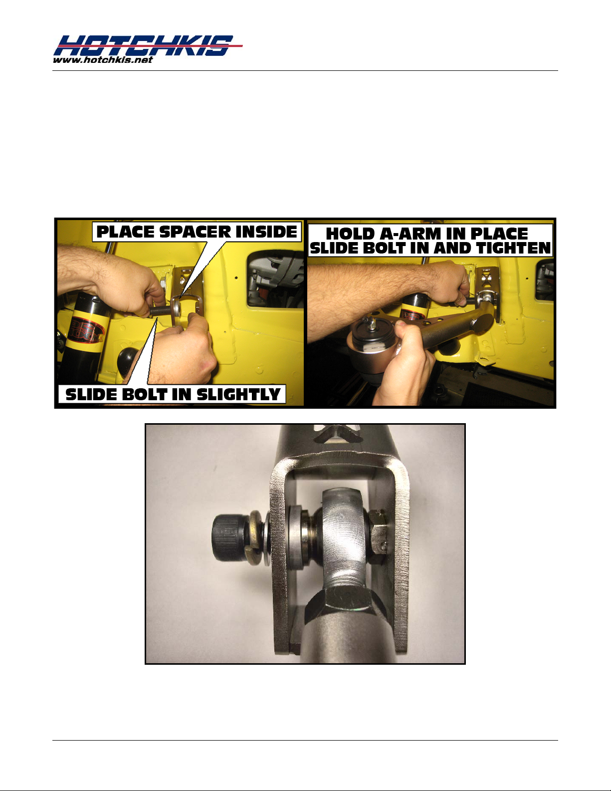
7. Install A-Arm Front Mount
Use hardware kit 17101 and install the split lock washer & AN washer onto each
½” socket-head bolt. Included in you’re A-Arm kit will be an assortment of
aluminum spacers with varying thicknesses. Grab one 0.185” spacer for each
Relocator. Insert the socket-head bolt slightly into the bottom hole of the A-Arm
Relocator just enough so you can rest the spacer on the tip of it on the inside of
the Relocator as shown below. Next, slide the A-Arm into place, slide bolt all the
way through, then fully tighten. See bottom picture for full detail.
1110 66-70 B-Body, 70-14 E-Body
Stack Up: 3/8” bolt---Split Lock washer---AN Washer---Relocator---
0.185” Spacer---Misalignment Spacer---Heim Joint
Hotchkis Performance LLC. 5
Page 6
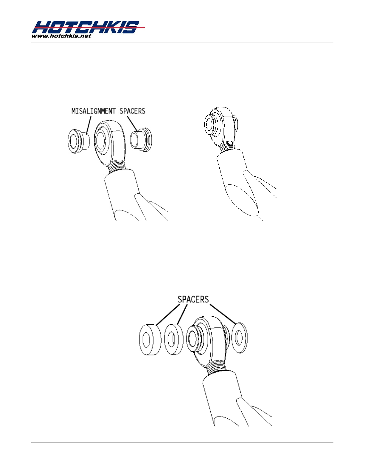
8. Install Other Side of A-Arm
The trailing end of the A-Arm will be bolted into the stock mounting hole. Install
2 misalignment spacers.
1110 66-70 B-Body, 70-14 E-Body
Position the A-Arm so that the other heim joint is lined up with the mounting hole.
You will notice there will be gaps on each side of the joint. You will need to add
spacers (included in your kit) to take up the gaps. These gaps are not consistent
from car to car so you will have to use the appropriate thickness spacers on
each gap. You may have to use combinations of varying thicknesses to
achieve proper gaping. See below as an example.
Hotchkis Performance LLC. 6
Page 7

1110 66-70 B-Body, 70-14 E-Body
Once the proper spacer arrangement is achieved, insert the camber bolt
through the stock mount hole and the other end will end up in the engine bay.
Install the camber washer and nut. Adjust the bolt so that the bolt is in the
center of its adjustment. Fully tighten nut for now. This will be adjusted once you
get an alignment.
9. Connect A-Arm to Spindle
Lift the A-Arm and lineup the ball joint stud to the hole in the spindle and slide
the stud in.
Hotchkis Performance LLC. 7
Page 8

1110 66-70 B-Body, 70-14 E-Body
10. Install Castle Nut
Install the castle nut to the other end of the ball joint stud and tighten until there
is clearance for the cotter pin to be inserted into the ball joint stud.
11. Install Cotter Pin
Install the cotter pin. Twist and cut as needed to ensure it stays in place.
Hotchkis Performance LLC. 8
Page 9

1110 66-70 B-Body, 70-14 E-Body
12. Install Bumpstops and Droopstops
Remove the stock droop stop and install the included Hotchkis “bullet” Shaped
version.
Remove the stock bump stop and install the included Hotchkis “Rectangle”
Shaped version.
Hotchkis Performance LLC. 9
Page 10

1110 66-70 B-Body, 70-14 E-Body
13. Repeat the steps for the other side and you’re done! Have an alignment shop align
the front end. Recommended performance specs:
Camber = 1° negative
Caster = As much positive caster as possible, as long as both sides have the same
spec.
Hotchkis Performance LLC. 10
Page 11

1110 66-70 B-Body, 70-14 E-Body
Hotchkis Performance LLC
Return Policy & Limited Warranty
Effective September 1, 2007. This return policy and limited warranty supersedes all previous policy and
warranty statements. Policies and warranties are subject to change without notice. Hotchkis
Performance is not responsible for printing errors.
Return Policy
We want you to be completely satisfied with your Hotchkis Performance product. In case you're not, you can
exchange or return it within 30 days of the purchase date. To obtain a full refund on unused products, excluding
freight, please contact our Customer Serv ic e Departm ent at (562) 907-7757 . You will be assigned a Retur ned Goods
Authorization Number (RGA). The package you return must sho w the RGA on the outside of the package , include
the original invoice and be shipped prepaid to our facility. The product has to be unused and in its original
packaging materials and be in sellable condition. For products prese nting signs of use or damage, only warranty
claims will be accepted. Exchanges or refunds made after 30 days will be subject to a 20% restocking charge. If
you purchased your Hotchkis Performance product from an authorized dealer, you are still covered by this return
policy. All returns however, should be made to your dealer , not to H o tchkis Performance directly.
Limited Warranty
Hotchkis Performance warrants its products against defects in materials and workmanship for the term of 36 months
(3 years) from the date of purchase. This Warranty only applies to the original retail purchaser who retains ownership
of the vehicle on which the product was originally installed. If the product i s d e termined to be defective, Hotchkis
Performance will repair, replace or refund the purchase price of the defective product at Hotchkis Performance's
sole discretion, which shall fully satisfy and di scharge any and all warranty claims. Any repaired or replaced product
will be returned to the sender freight prepaid.
Exclusions from Warranty
Items offered but not manufactured by Hotchkis Performance are warranted according to the
manufacturer's te rms and are not covered by th is limited warranty. Hotchkis Performance shall not be
responsible for any labor, removal, installation, re-installation or maintenance costs. This warranty does
not cover the cosmetic finish or plating of any product or any normal wear and tear to any product. In
addition, this warranty does not apply to any products that have been:
Improperly installed or installed by someone other than a qualified, licensed auto mechanic
experienced in the installation and removal of suspension products;
Improperly serviced, misused, or modified, altered or subjected to abuse, negligence, accident or
collision;
Installed in any vehicle that has been modified;
Installed on any vehicle that has carried loads in excess of automobile manufacturer suggested
weight limits; or
Installed on any vehicle that has been subject to abnormal or excessive use, including rallying,
racing or racing-type activities or off-road use.
Limitation of Warranty
This limited warranty is the entire and only warranty for the products and may not be modified or
supplemented by any other person or company in any form. Any description of the products, by
anyone, is for the sole purpose of identifying them and is not part of the basis of the bargain, and does
not constitute a warranty that the products will conform to that description. The statements of any
salesperson do not constitute part of this limited warranty and cannot be relied upon as a warranty.
Hotchkis Performance LLC. 11
Page 12

1110 66-70 B-Body, 70-14 E-Body
THERE ARE NO WARRANTIES, EXPRESSED OR IMPLIED, INCLUDING ANY IMPLIED WARRANTIES OF
MERCHANTABILITY OR FITNESS FOR A PARTICULAR PURPOSE, WHICH
EXTEND BEYOND THE DESCRIPTION ON THE FACE HEREOF. ANY IMPLIED WARRANTIES ARE DISCLAIMED TO
THE FULLEST EXTENT PERMITTED BY LAW. THIS WARRANTY DOES NOT COVER CONSEQUENTIAL DAMAGES,
LOSS OF TIME OR REVENUES, INCONVENIENCE, LOSS OF USE OF THE VEHICLE, DAMAGE TO THE VEHICLE OR
COMPONENTS OF THE VEHICLE, ANY OTHER TYPE OF CONSEQUENTIAL DAMAGES, OR OTHER INCIDENTAL
OR INDIRECT DAMAGES. HOTCHKIS’ MAXIMUM LIABILITY UNDER THIS WARRANTY SHALL IN NO EVENT
EXCEED THE PURCHASE PRICE OF THE PRODUCT. Some states do not allow limitations on how long an
implied warranty lasts or the exclusion or limitation of incidental or consequential damages and in such
states the above limitations or exclusions may not apply. This limited warranty gives the purchaser
specific legal rights and the purchaser may have other rights that may vary from state to state.
Technical Information
Hotchkis Performance makes every effort to ensure that you are provided with the most accurate and
up-to-date technical information. However, all technical information is approximate and may vary
upon application. Additional suspension components may be needed in some applications, depending
upon the make, model, engine and chassis of the vehicle. Hotchkis Performance is not responsible for
any consequences resulting from manufacturer’s technical mid-year changes. Hotchkis Performance
products should only be installed by a qualified, licensed auto mechanic experienced in the installation
of such products.
Warranty Claim Procedure:
The answer to ALL the following questions should be YES before making a warranty claim:
Is the product appropriate to your application?
Did you carefully and thoroughly read the instructions provided along with the product?
Do you have the original invoice or sales receipt?
Is the return date within 36 months from the purchase date?
Are you the original purchaser?
Was the product properly installed by a qualified, licensed auto mechanic?
Has the product been installed on the original vehicle on which it was installed at all times?
Is the product unmodified and clean?
Is the reason for return a legitimate product defect?
If the answer to all these questions is YES, please contact our Customer Service Department at (562) 907-
7757. You will be given a Returned Goods Authorization Number (RGA) valid for 60 days. You will also be
asked to ship the product prepaid to our facility. All shipments MUST be (i) prepaid, (ii) include the
original invoice or sales receipt, (iii) show the RGA on the outside of the package and (iv) include your
name, address, make and model of the vehicle, and a brief description of the claimed defect,
including the circumstances under which the defect occurred. Warranty related inquires should be
sent to the following address:
HOTCHKIS PERFORMANCE, LLC
C/O CUSTOMER SERVICE
12035 BURKE ST. SUITE 13
SANTA FE SPRINGS, CA 90670
Hotchkis Performance will not accept product returns without the RGA number, receipt and the
information described above. C.O.D. or collect shipment s will be re fuse d. Once the returns are rece ive d
at Hotchkis Performance, we will evaluate the products, verify the sales receipt, and investigate the
warranty claim.
Hotchkis Performance LLC. 12
Page 13

14385 A-Body, 14366 66-70 B-Body, 70-74 E-Body
14366, 14385
Adjustable Strut Rods
67-76 Chrysler A-Body
1966-1970 Chrysler B-Body
1970-1974 Chrysler E-Body
Thank you for your purchase from our new line of B & E-Body parts.
Please call us at (877) 4NO - ROLL if you have any questions
regarding the service or installation of your Hotchkis products.
Hotchkis Performance LLC . 1
Page 14

14385 A-Body, 14366 66-70 B-Body, 70-74 E-Body
Before You Start :
Please read the entire manual before starting. Most pictures shown are of the
passenger side strut rod. Please perform the same procedure for the driver side.
1. Raise Vehicle
Raise the vehicle and put it up on jack stands. You may al so use a 2-post or 4post lift.
2. Disconnect the Front Sway Bar
If your car has a front sway bar, disconnect the front sway bar ends that attach
to the lower control arms.
3. Disconnect the Strut Rod From the K-Member
Undo the strut rod nut accessible from the front of the K-member. You may
discard this hardware.
4. Disconnect Strut Rod From Lower Control Arm
In order to get the stock strut rod out, you w ill need to shift the lower control arm
toward the rear of the car to gain more room. First undo the nut securing the
strut rod to the lower control arm. Retain this nut for reinstallation.
Loosen the torsion bar tensioner bolt located on the bottom of the lower control
arm to relieve the load from the torsion bar.
Next, loosen and remove the main nut securing the lower control arm to the kmember.
There is a snap ring at the rear end of the torsion bar that keeps it from moving
back. Remove the snap ring and shift the torsion bar 3-4” towards the back.
You should be able to shift the lower control arm slightly towards the back
allowing you to pop out the strut rod end out of the lower control arm hole.
The stock strut rod should be free from the vehicle.
Hotchkis Performance LLC . 2
Page 15

14385 A-Body, 14366 66-70 B-Body, 70-74 E-Body
5. Install Clevis Assembly onto Strut Rod
Install 2 misalignment spacers onto the heim joint. Insert the ½” bolt, washers
and nuts onto the clevis assembly attaching the clevis to the heim joint. Fully tighten
the ½” bolt
Hotchkis Performance LLC . 3
Page 16

6. Install the Strut Rod
We’ll start by bolting in the front end first. Following the diagram below to see
the order of parts.
14385 A-Body, 14366 66-70 B-Body, 70-74 E-Body
Install the large flat-cut washer onto the clevis stud and insert the front mount into the
k-member hole.
If needed, rotate the flat-cut washer to alleviate any clearance issues with the sheet
metal.
You will notice that the k-member hole is much larger than the clevis stud. This is ok,
since you will be inserting 2 spacer washers from the front side of the k-member to take
up the gap. The spacer washers will fit inside the k-member sheet metal.
Once the spacers are in place, install the large round washer and 5/8” nylock nut.
Moving on to the rear mount, insert the rear stud into the lower control arm hole. Do
not install the stud nut at this time.
Hotchkis Performance LLC . 4
Page 17

14385 A-Body, 14366 66-70 B-Body, 70-74 E-Body
Reinstall the lower control arm back onto the k-member. Push the torsion bar forward
and insert it into the lower control arm pin hex.
Next rotate/thread the strut rod body in or out to a desired length. You can dial in
more positive caster by shortening the strut rod. Do not over extend the strut rod past
the recommended length (see diagram below). Fully tighten the rear strut rod nut.
Center the heim joint so that it is not twisted one way or another. Tighten the heim
joint jam nut.
Fully tighten the front strut rod 5/8” nut you installed earlier. To avoid spinning the clevis
while tightening, use a pry bar to hold the clevis.
Restore torsion bar snap ring. Adjust the torsion bar tensioner back to where it was for
proper pre-load.
Hotchkis Performance LLC . 5
Page 18

14385 A-Body, 14366 66-70 B-Body, 70-74 E-Body
7. Repeat on Drivers Side
Repeat the steps on the driver’s side and you’re done!
Hotchkis Performance LLC
Return Policy & Limited Warra nty
Effective December 1, 2010 all Hotchkis products must be registered to qualify for warranty at
www.hotchkis.net
the original purchase date.
IMPORTANT: This warranty supersedes all other warranties included with this product.
Return Policy
We want you to be completel y satisfied with your Hotchk is Perform ance product. For products, presenting signs
of shipping damage pleas e contact the freight carrier immediately. All our pr oducts are guaranteed to be free
from manufacturer’s defects. If your order arrives with a manufacture defect, please contact our Customer
Service Department at ( 562) 907-7757. You will be ass igned a Returned Goods Authorizati on Number (RGA).
The package you ret urn must show the RGA on the outside of t he package, include the original invoice and be
shipped prepaid to our fac ility. The product has t o be unused and in its original pack aging m aterials. Exchanges
or refunds made after 30 days will be subject to a 20% restoc king charge. If you purchased your Hotchkis
Performance product from an authorized dealer, you are still covered by this return policy. All returns
however, should be made to your dealer, not to Hotchkis Performance directly.
Limited Warranty
or via the mail-in warranty card, included with the product, within 30 days of
Hotchkis Performance LLC . 6
 Loading...