

Page 1
2236 Sway Bar Install a tion Instructions
Thank you for your purchase of this Hotchkis Performance product . Your stabilizer bar set was
designed with the performance and durability you’ve come to expect from Hotchkis Performance.
Special Note:
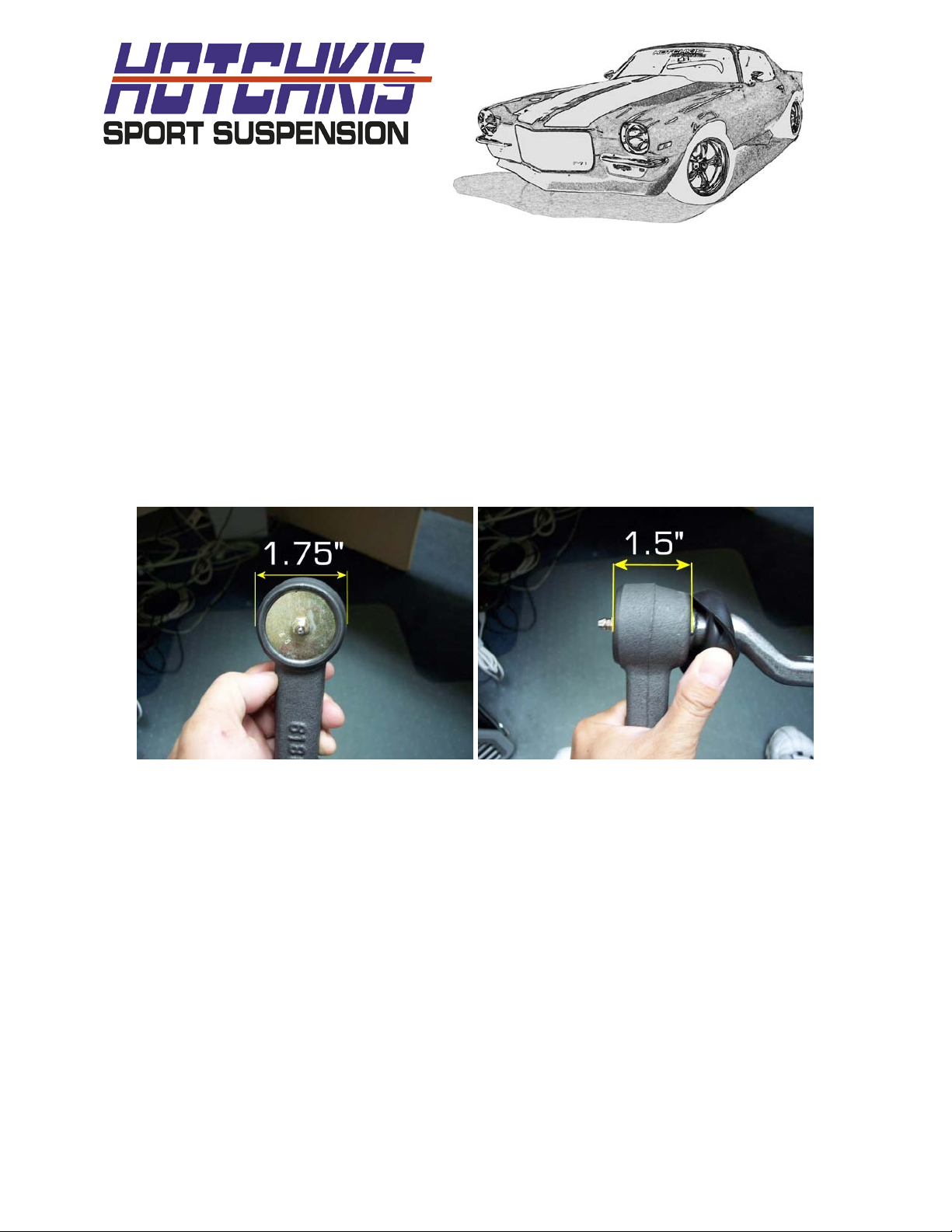
We’ve noticed that our front sway bar only works wit h certain steering idler arms. The pr oblem is
that some aftermarket idler a rms have larger body diameters. This causes clearanc es issues. The
original GM idler arm clear s just fine. If you need to replace your idler arm make sure the ball joint
body diameter is 1.75” and the body height is 1.5”. See photos below.
The replacement idler arm ca n be found from Classic Industries pa r t # 18753
Front Bar Installation:
1F. Look at the current bar i nstallation and note t he position of the anti-sway bar.
2F. Loosen, but do not remove the front bushing bolts.
2236 GM F-Body Stabilizer Bar Installation Instructions Page 1 of 16
Page 2
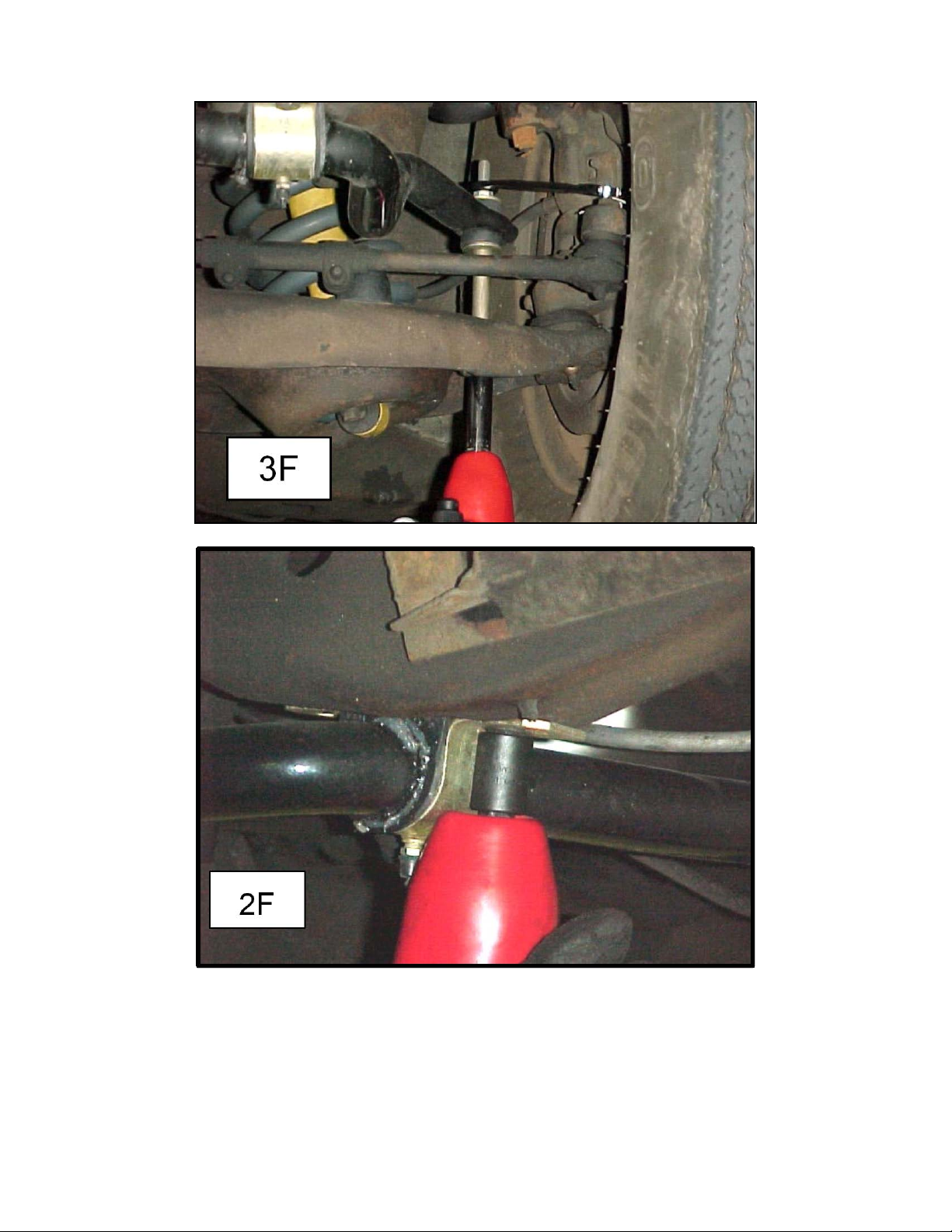
3F. Remove the endlinks from the sway bar and lower c ontrol arms.
2236 GM F-Body Stabilizer Bar Installation Instructions Page 2 of 16
Page 3
4F. Take the bolts out of the frame brackets and remove the stock sway bar from the vehicle.
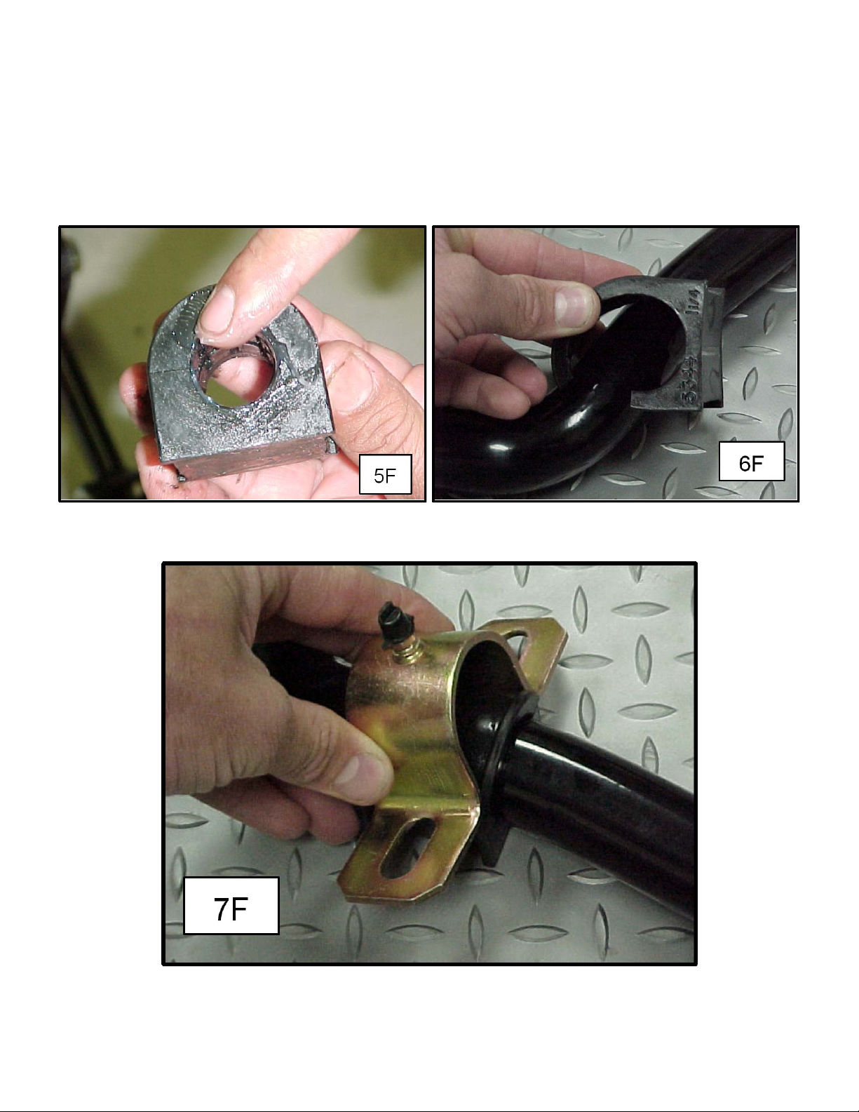
5F. Using the included white silicon grease, lube the inside of the new 1 3/8” front bushings.
NOTE: the grease can be cleaned up with WD-40
6F. Install the bushing on the new Hotchkis bar. Make sure the split on the bushing faces the front
when the bar is installed in the vehicle. Look at the placement of the original stock bushings
on the stock bar for guidance.
7F. Place the greasable bracket over top the bushing.
2236 GM F-Body Stabilizer Bar Installation Instructions Page 3 of 16
Page 4

8F. Put the new bar assembly into the vehicle and start the frame bolts. Do not tighten the frame
bolts completely, only start enough threads to hold the bar in place while your work on the
endlinks
9F. Install the new endlinks and tighten them till the bushings are squeezed just enough that their
diameter is just larger than the supporting washer.
10F. Tighten the frame bracket bolts.
2236 GM F-Body Stabilizer Bar Installation Instructions Page 4 of 16
Page 5
Rear Bar Installation:
1R. Jack up the vehicle and properly support with jack stands or lift jacks. Make su re the rear end
is supported with the vehicle’s load on the leaf springs. This is to ensure yo u i nstall the rear
bar in the proper position.
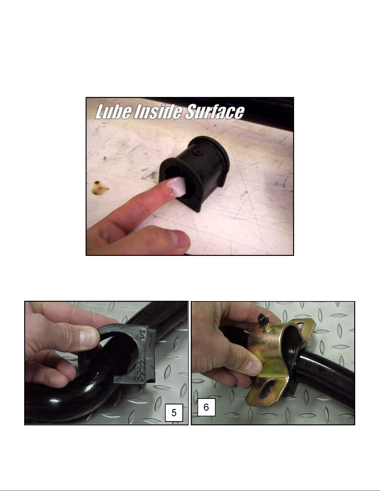
2R. Take the bushings and grease the inner surface with the included white silicon grease.
3R. Install the bushings on the ba r . (5) Place the bracket over top of the bushing. (6)
2236 GM F-Body Stabilizer Bar Installation Instructions Page 5 of 16
Page 6
4R. Take the sway bar assembly and hold it up under the rear end of the car. The arms will point
forward and the dog bone end links point up. Check for exhaust clearance in this area. You
may have to have the exhaust pipes re-bent to provide clearance for the new sway bar
assembly. Any competent exhaust shop can handle this modificat ion easily.
5R. After you determine there’s enough clearance for the bar, note the approximate location o f the
sway bar axle bushing.
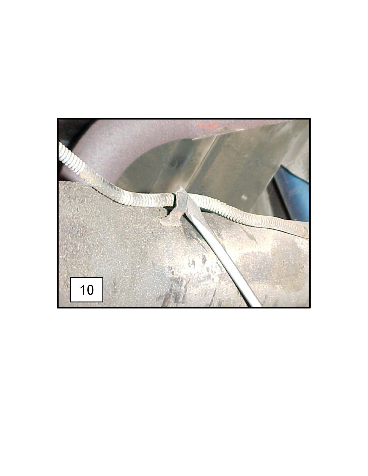
6R Take a screwdriver and ca r efully pry up the brake line to allow the U-Bolt to drop down over
the axle. (10)
7R Install the U-Bolts on the axle and slip the axle bracket over the U-Bolt on the bottom side of
the axle. Use masking or duct tap e to secure them. Place the sway bar assembly under the
axle and slip the U-bolt legs t hr ough the sway bar brackets. Place washers and nylock nuts on
the U-Bolt. Snugly fasten the nylock nuts a bit , but do not fully tight en at this time.
2236 GM F-Body Stabilizer Bar Installation Instructions Page 6 of 16
Page 7

2236 GM F-Body Stabilizer Bar Installation Instructions Page 7 of 16
Page 8

8R
Undo Frame Rail Lines
We are going to be mounting the dog bone endlinks to the frame rails. However, we first
need to access the side of the frame rails. We will need to undo the fuel/brake lines that are
mounted to the rails.
The driver side has a brake line and vent line that is mounted to the frame rail. Undo the line
tabs as shown in the picture below.
2236 GM F-Body Stabilizer Bar Installation Instructions Page 8 of 16
Page 9

The passenger side has the fuel line mounted to the frame rail. Undo the line tabs as shown
in the picture below.
2236 GM F-Body Stabilizer Bar Installation Instructions Page 9 of 16
Page 10

9R
Install Frame Rail Reinforcements
We will be installing reinforcement p l ates onto the frame rails. T his will require drilling two ¾”
holes for through each frame rail.
Start on the passenger side frame rail. The hole that was used to hole the line tab is in the
same position as one of your holes. (see picture) Use one o f the reinforcement plates as a
template to mark out the other hole.
2236 GM F-Body Stabilizer Bar Installation Instructions Page 10 of 16
Page 11

Drill out the ¾” hole only on the inner side of the frame rail. Do not d r i ll through both walls of
the frame rail. We found that a unibit works best.
2236 GM F-Body Stabilizer Bar Installation Instructions Page 11 of 16
Page 12

Insert the reinforcement plate with the 2 tubes welded to it into the frame rail. Use a vise
clamp to secure the plate onto the frame rail. Drill the outer wall of the frame rail wi th a ½”
drill bit. The reinforcement t ubes will act as a guide for yo u to drill. So when you are finished,
you will have two ¾” holes on t he inside of the frame rail and two ½” holes on the outer
sided of the frame rail.
2236 GM F-Body Stabilizer Bar Installation Instructions Page 12 of 16
Page 13

Remove the vise clamp and insert 1 short bolt w/ washer and 1 long bolt w/ washer from the
outside of the frame rail. ( hardware kit #1757) Make sure to add the other reinforcement
plate to the outside befo r e you insert the bolts through the frame.
2236 GM F-Body Stabilizer Bar Installation Instructions Page 13 of 16
Page 14

Install a washer and a nut to the top (shorter) bolt. Do not fully tig hten this bolt at this time.
(hardware kit #1757)
2236 GM F-Body Stabilizer Bar Installation Instructions Page 14 of 16
Page 15

Grease up your new dog bone end links with the provided grease. Install the dog bone on the
bottom (longer bolt) with the grease fittings pointing rearward.
Install the line bracket onto the long bolt and install a washer and nut. Do not fully tighten at
this time. (hardware kit #1757)
2236 GM F-Body Stabilizer Bar Installation Instructions Page 15 of 16
Page 16

Line up the mounting tab with the line bracket you just instal led. Use the provided 5/16” bolt
and washer to secure the mounting tab to the line bracket. (hardware kit #1757) Mak e su re
the ½” Nut is not too close to the fuel line.
2236 GM F-Body Stabilizer Bar Installation Instructions Page 16 of 16
Page 17

Fully tighten both short and long bolts completely.
You’re given new hardware for a ttaching the dog bone end l inks to the sway bar. Use the
bolts, nuts, and washers from the hardware kit.
2236 GM F-Body Stabilizer Bar Installation Instructions Page 17 of 16
Page 18

Once the passenger side is completely mounted together, you can now fig ur e out where the
other frame rail reinforcement pl ate goes on the driver side. Mock up the driver side dog bone
end link onto the sway bar and mark where the bottom hole should be. Again, use the
reinforcement plate as guide t o mark the upper hole. Drill the holes in the same manner as
before.
You can remove the mounting tabs that are no longer in use.
2236 GM F-Body Stabilizer Bar Installation Instructions Page 18 of 16
Page 19

10R
Double Check all Hardware
Double check and make sure all hardware is full tightened before driving the vehicle. You are
finished with the rear sway bar kit.
2236 GM F-Body Stabilizer Bar Installation Instructions Page 19 of 16
Page 20

Hotchkis Performance LLC
Return Policy & Limited Warranty
Effective December 1, 2010 all Hotchkis products must be registered to qualify for warrant y at
www.hotchkis.net or via the mail-in warranty card, included with the product, within 30 days of the original
purchase date.
IMPORTANT: T his warranty supersedes all other warranties included with this product.
Return Policy
We want you to be completely satisfied with your Hotchkis Performance product. For products, presenting signs
of shipping damage please contact the freight carrier immediately. All our products are guaranteed to be free
from manufacturer’s defects. If your order arrives with a manufacture defect, please contact our Customer
Service Department at (562) 907-7757. You will be assigned a Returned Goods Authorization Number (RGA). The
package you return must show the RGA on the outside of the package, include the original invoice and be
shipped prepaid to our facility. The product has to be unused and in its original packaging materials. Exchanges
or refunds made after 30 days will be subject to a 20% restocking charge. If you purchased your Hotchkis
Performance product f rom an authorized dealer, you are still covered by this return policy. All returns however, should be
made to your dealer, not to Hotchkis Performance directly.
Limited Warranty
Hotchkis Performance offers a Limited Warranty against defects in materials and workmanship for the term of 36
months (3 years) fr o m th e date of purchase of this pr o d u ct. This Warranty only applies to the original retail
purchaser who retains ownership of the vehicle on which the product was originally installed. If the product is
determined to be defective, Hotchkis Performance will repair, repla ce or refund the purchase price of the
defective product at Hotchkis Performance's sole d iscretion, which shall fully satisfy and di scharge any and all
warranty claims. Any repaired or replaced product will be returned to the sen d er excluding the cost of freight.
Products must be registered to qualify for warranty at www.hotchkis.net or via the mail-in warranty card, included with the
product, within 30 days of the original purchase date.
Exclusions from Warranty
Items offered but not manufactured by Hotchkis Performance are warranted according to the manufacturer's
terms and are not covered by this limited warranty. Hotchkis Performance shall not be responsible for any labor,
removal, installation, re-installation or maintenance costs. This warranty does not cover the cosmetic finish or
plating of any product or any normal wear and tear to any product including, but not limited to bushings,
brackets, end-links, hardware, steering components, shocks or springs. In addition, this warranty does not apply
to any products that have been:
Improperly installed or installed by someone other than a qualified, licensed auto mechanic experienced in
the installation and removal of suspension products;
Improperly serviced, misused, or modified, altered or subjected to abuse, negligence, accident or collision;
Installed in any veh icle that has been modified ;
Installed on any vehicle that has carried loads in excess of automo b ile manufacturer sugge sted weight limits;
or
Installed on any vehicle that has been subject to abnormal or excessive use, including rallying, racing, or
racing-type activities or off-road use.
Limitation of Warranty
This limited warranty is the entire and only warranty for the products and may not be modified or supplemented
by any other person or company in any form. Any description of the products, by anyone, is for the sole purpose
of identifying them and is not part of the basis of the bargain, and does not constitute a warranty that the
products will conform to that description. The statements of any salesperson do not constitute part of this
limited warranty and cannot be relied upon as a warranty.
THERE ARE NO W ARRANTIES, EXPRESSED O R IMPLIED, INCLUDING ANY I MPLIED WARRANTI ES OF
MERCHANTABILITY OR FITNESS FOR A PARTICULAR PURPOSE, WHICH EXTEND BEYOND THE
DESCRIPTION ON THE FACE HEREOF. ANY IMPLIED WARRANTIES ARE DISCLAIMED TO THE
FULLEST EXTENT PERMITTED BY LAW. THIS WARRANTY DOES NOT COVER CONSEQUENTIAL
2236 GM F-Body Stabilizer Bar Installation Instructions Page 20 of 16
 Loading...