

Page 1
Sport Sway Bar Kit 22108
67-72 C-10 Truck
Thank you for your purchase from our new line of Chevy parts.
Please call us at 877 - 4NO - ROLL if you have any questions
regarding the service or instal lation of your Hotchkis Performanc e products.
IMPORTANT: PLEASE READ THE ENTIRE
STARTING THIS INSTALLATION. THIS INSTALLATION DEPICTS A TRUCK THAT
DID NOT HAVE A SWAY BARS FROM FACTORY.
INSTRUCTION MANUAL BEFORE
1F
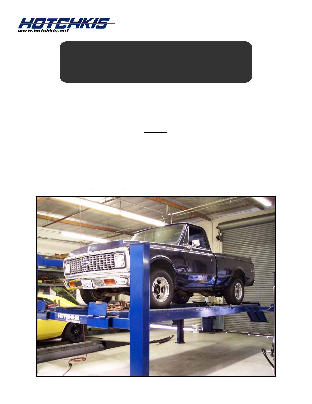
Raising Vehicle
Raise front of the vehicle by using a 4 post lift or drive-on ramps. Securely block the rear
wheels of the vehicle. Do not remove the front wheels during installation. It is imperative
that the vehicle is at ride height for this installation.
Page 2
2F
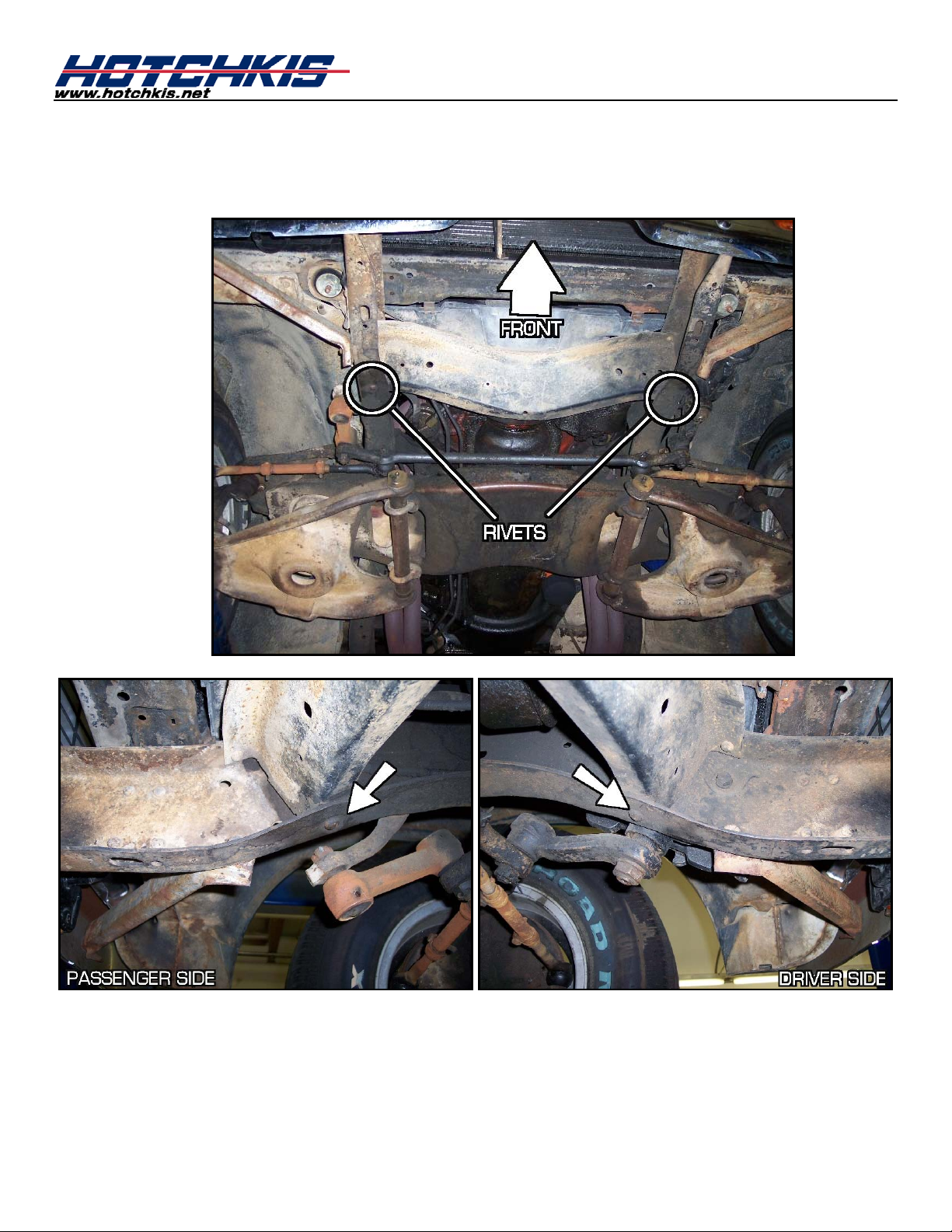
Install Frame Mounts
First step is to install the frame mounts. The mounts utilize existing rivet holes in the frame.
You will need to air chisel the rivets as shown below.
Page 3
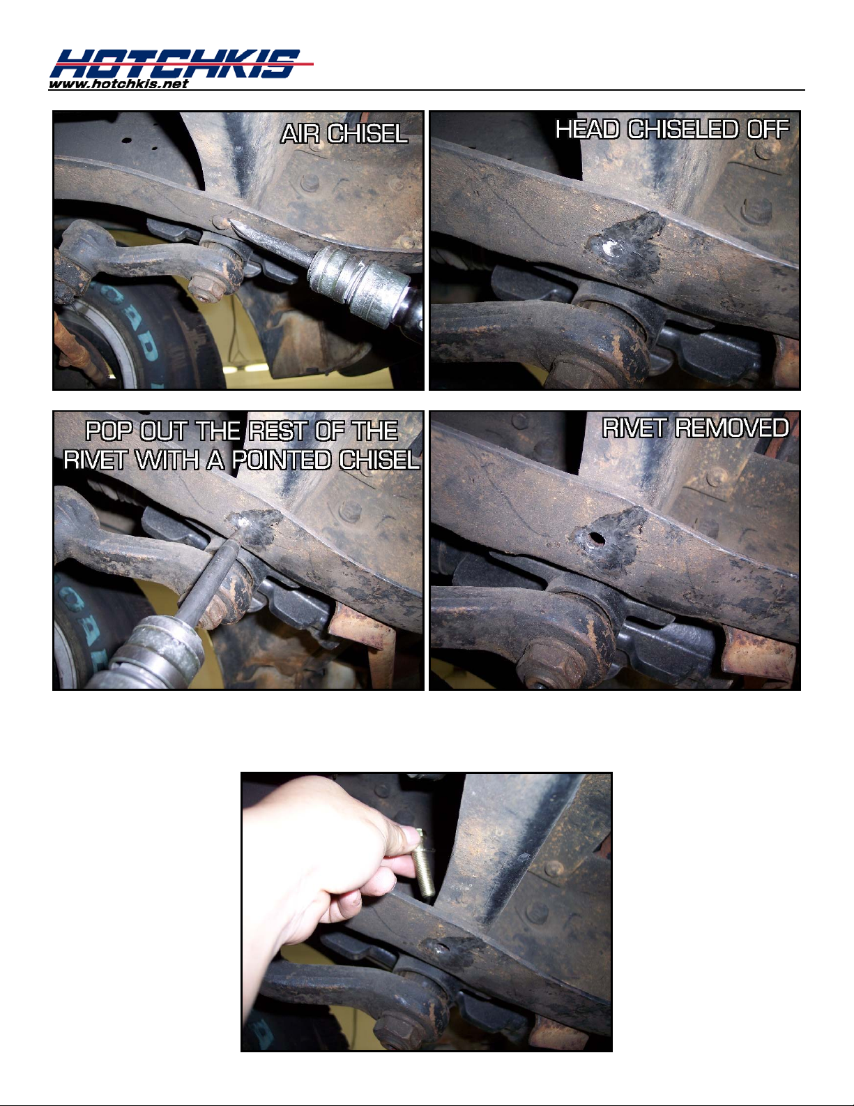
Once the holes are clear, grab the 3/8” x 1.5” hex bolts & washers from the “front” hardware
bag and insert them into the rivet holes facing down.
Page 4

Position the mounting bracket to the frame rail and begin fastening the 3/8” bolts with the
provided washers and nylock nuts. Do not tighten all the way!
Grab the 3/8” x 1.25” hex bolts and drop them into the mount holes on the bracket itself.
Don’t forget to use washers.
You can now fully tighten the frame bolts at this time.
Page 5
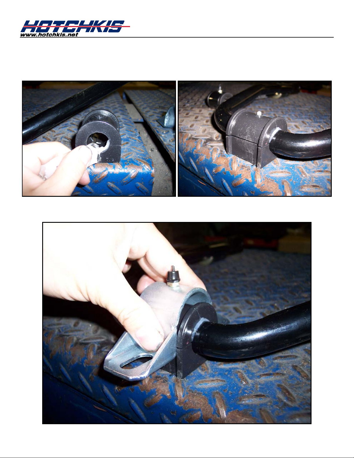
3F
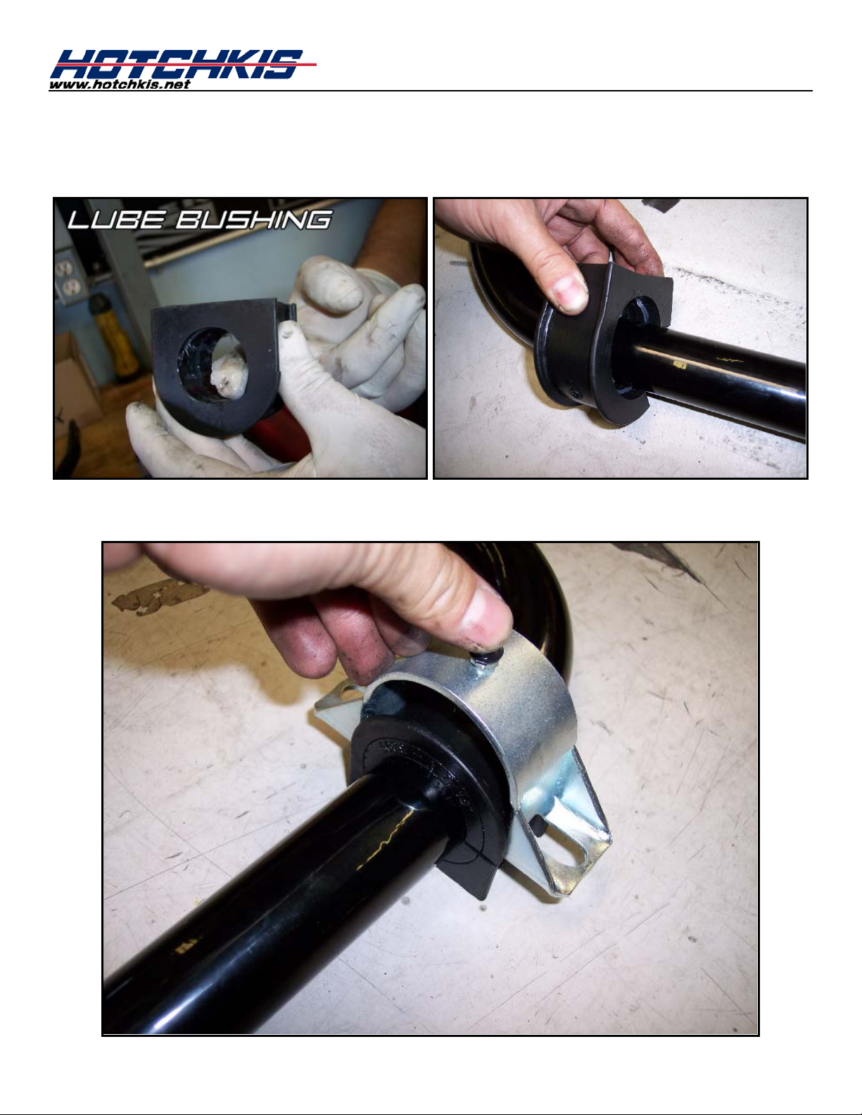
Install Bushings & Brackets
Next grease the inner surface of the provided polyurethane bushings and install them onto the
sway bar near to the bends.
Slide the bushing brackets onto the bushings as shown below.
Page 6
4F
5F
Mount Bar onto Truck
Position the sway bar up to the frame mounts. Using the 3/8” hardware from the kit, start
fastening the bushing brackets o nto the frame mounts. Do not fully tighten these yet.
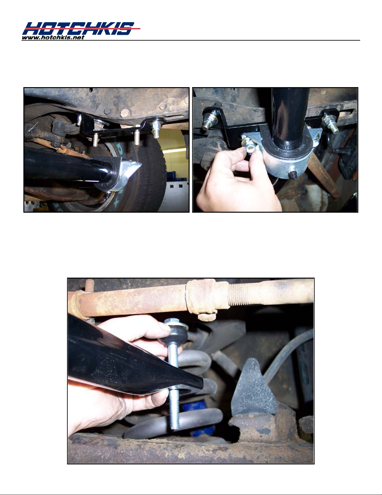
Install End Links
The front lower a-arms have an existing ho le that the sway bar end links will utilize.
First open up the 25108 end link kit. Grab the long bolt along with a large washer and
bushing. Insert the bolt/washer/bushing into the sway bar hole from the top.
Page 7

Next install additional large washers & bushings in the order shown below.
Insert the bolt through the a-arm and install the smaller diameter bushing and a small washer
from the bottom of the arm. Tighten everythi ng with the included nylock nut.
Page 8
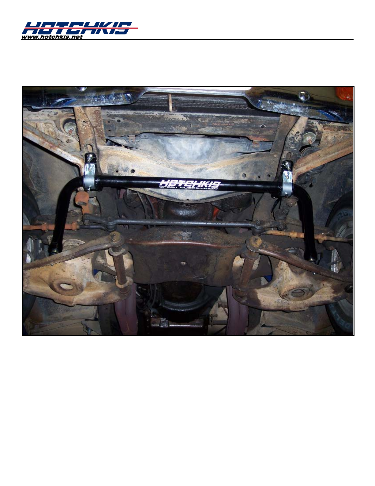
6F
Finish Up
Finish the installation by fully tightening the bushing bracket bolts. Double check all hardware
for tightness and you are done with t he fr ont.
Page 9
Installation of Hotchkis Rear Sway Bar
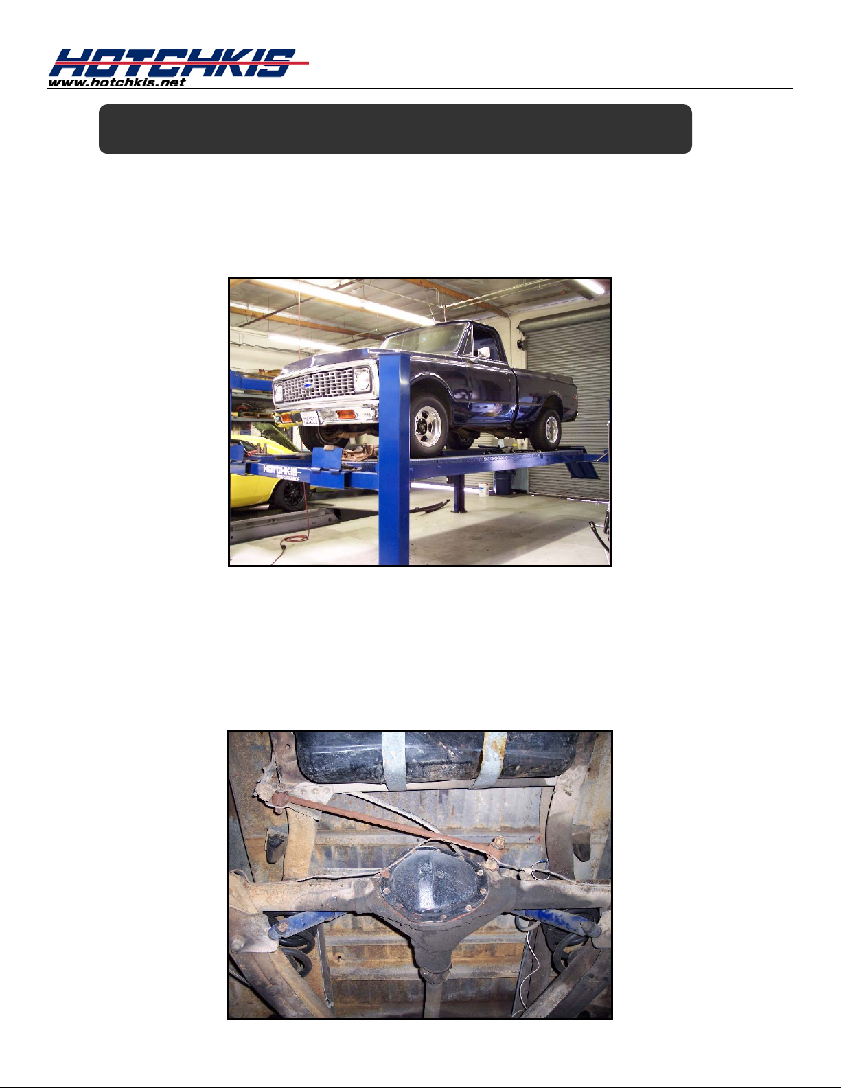
1R
Raising Car
Raise rear of the vehicle by using a 4 post lift or drive-on ramps. Securely block the front
wheels of the vehicle. Do not remove the rear wheels during installation. It is imperative that
the vehicle is at ride height for this installation.
2R
Install U-Bolts (kit#T1722) on Rear Axle
Take the washers and nuts off of the U-bolts and slide them on top of the axle tubes on each
side. They should be centered and approx. 27” apart from each other. If you have any brake
lines in the way, you must relocate them. This could be as easy as unclipping them and
bending them away from the axle tubes. Apply the supplied anti-seize to the threads of the Ubolts.
Page 10
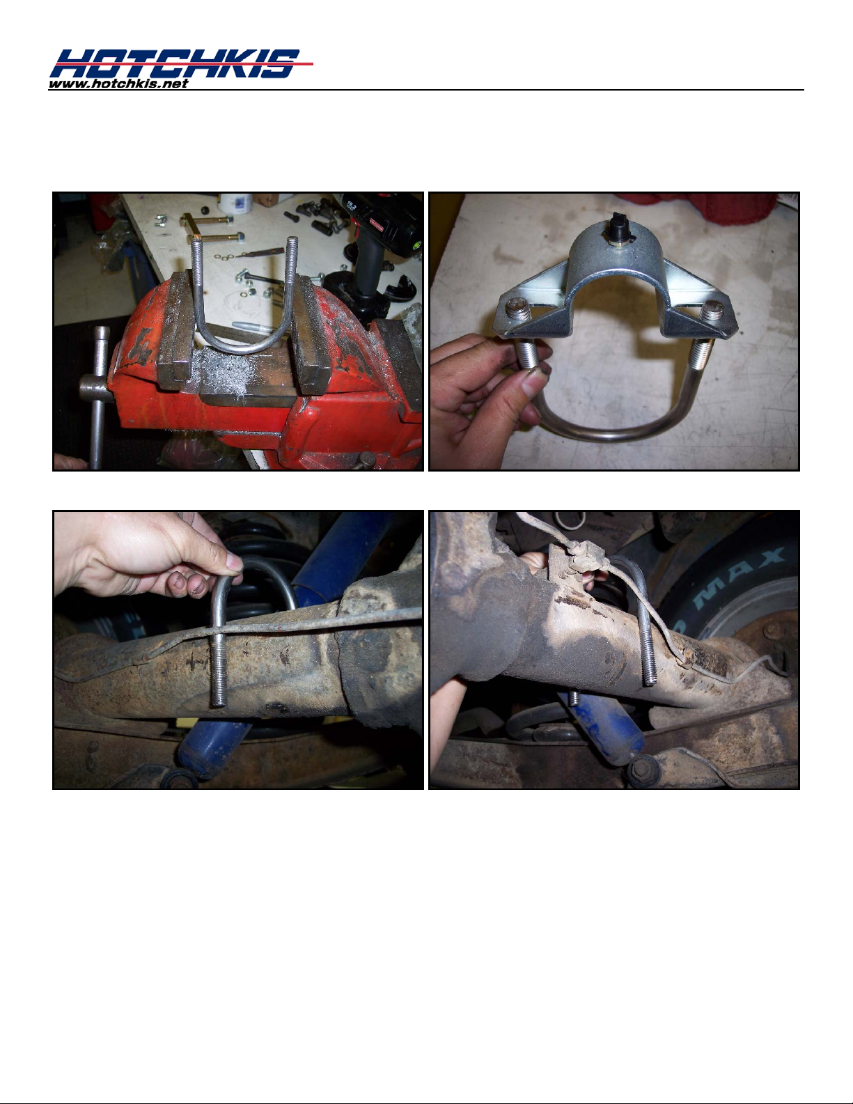
Before installing the U-bolts, first check the distance between the U-bolt ends. Grab a bus hi ng
bracket and line up the holes with the U-bolt. If the U-bolt span is larger than the bracket
holes, you can easily squish the U-bolt slightly with a vise to get the proper span. See Below.
Page 11
3R
Install Bushings & Brackets
Next grease the inner surface of the provided polyurethane bushings and install them onto the
sway bar near to the bends.
Slide the bushing brackets onto the bushings as shown below.
Page 12
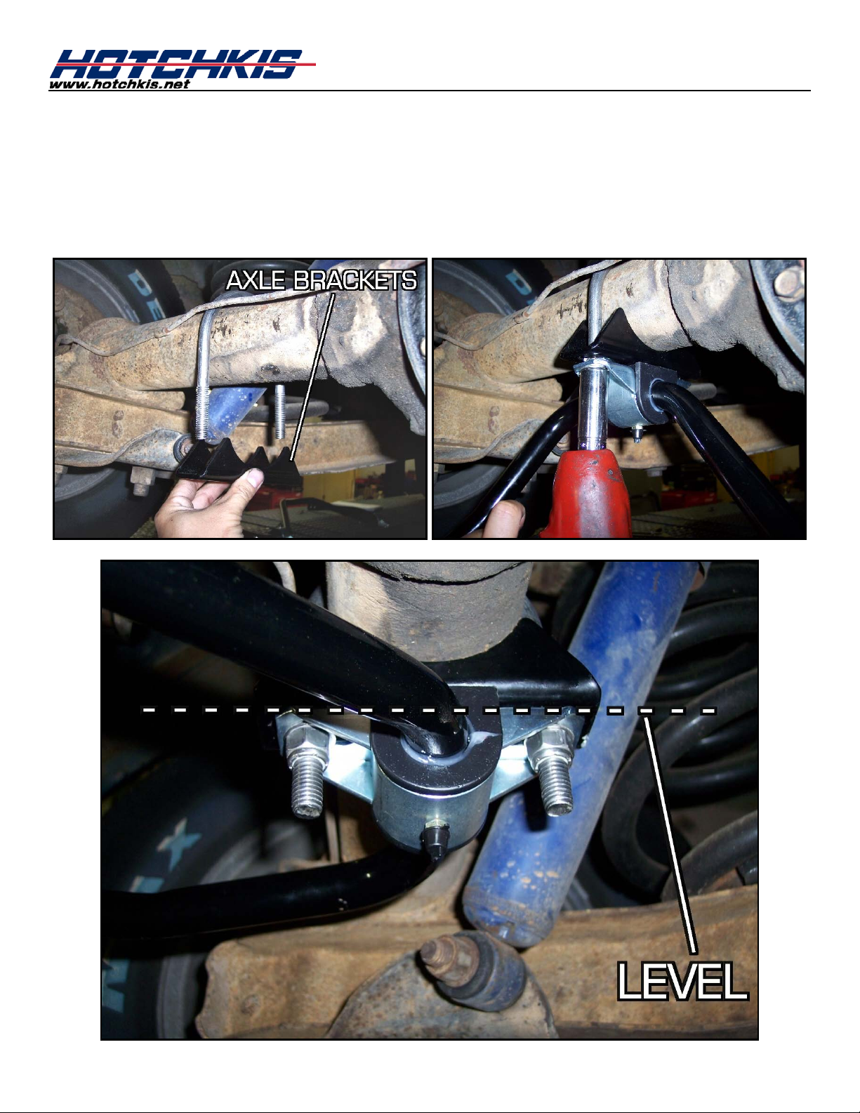
4R
Now we are going to bring the assemble sway bar to the rear axle. Also grab the axle
Mount the Sway Bar onto the Rear Axle
brackets at the same time. These will have to go on between the axle and the bushing
bracket. See picture for more details. When tightening the u-bolt nuts, make sure the u-bolt
is pointing straight down. I.e. The u-bolt should not be at an angle with the ground. Also
tighten the U-bolt nuts evenly and in sma ll amounts at a time.
Page 13

5R
Drill Holes for the Passenger End Link
The driver side frame rail has an existing hole for it’s end link, but you’ll need to drill a hole for
the passenger side. But first we need to measure the driver side hole location. A good
reference point for the hole is the bigger hole near the edge shown in the picture below.
Measure the distance forward from the big hole to the little hole. It should be around 1.5”.
Go to the passenger side frame rail and measure the same dimension and mark the frame
with a paint pen. Drill out the hole using a 7/16” drill bit.
Page 14

6R
Grease the side surfaces of the end link bushings. Install the stud end onto the frame rail
Install End Links (P/N:T2233)
holes. The frame rail gets sandwiched by the bushings. Do not fully tighten the upper nut
yet.
Page 15

Rotate the sway bar up to the end link until the holes line up. You can use either hole based
on stiffness preference. The hole closest to the end is the softer setting. Use the hardware in
the “Rear” Bag as shown below.
Page 16

8R
Make sure all hardware is fully tightened before driving the vehicle. You are done with the
Double Check Hardw a re
installation. The vehicle does not r eq ui r e an alignment after this installatio n.
Page 17

Hotchkis Performance LLC
Return Policy & Limited Warra nty
Effective December 1, 2010 all Hotchkis products must be registered to qualify for warranty at
www.hotchkis.net or via t he mail-in warranty card, included with the product, within 30 days of the
original purchase date.
IMPORTANT: This warranty supersedes all other warranties included with this product.
Return Policy
We want you to be completely satisfied with your Hotchkis Performance product. For products, presenting signs of
shipping damage please contact the freight carrier immediately. All our products are guaranteed to be free from
manufacturer’s def ec ts . If your order arr i ves wit h a manufacture def ec t, pl ease contact our Cust omer Service Department
at (562) 907-7757. You will be ass igned a R eturned Goods Authorizat ion Num ber (RGA). The pack age you return m ust
show the RGA on the out side of the package, include the original invoic e and be shipped prepaid to our facility. The
product has to be unused and in its original packaging materials. Exchanges or refunds made after 30 days will be
subject to a 20% restocking charge. If you purchased your Hotchkis Performance product from an authorized
dealer, you are still covered by this return policy. All returns however, should be made to your dealer, not to
Hotchkis Performance directly.
Limited Warranty
Hotchkis Performance offers a Limited Warranty against defects in materials and workmanship for the term of 36 months
(3 years) from the date of purchase of this product. This Warranty only applies to the original retail purchaser who retains
ownership of the vehicle on which the product was originally installed. If the product is determined to be defective,
Hotchkis Performance will repair, replace or refund the purchase price of the defective product at Hotchkis Performance's
sole discretion, which shall fully satisfy and discharge any and all warranty claims. Any repaired or replaced product will
be returned to the sender excluding the cost of freight.
www.hotchkis.net or via the mail-in warranty card, included with the product, within 30 days of the original
purchase date.
Products must be registered to qualify for warranty at
Exclusions from Warranty
Items offered but not manuf actured by Hotchkis Performanc e are warranted according to the manufac turer's terms and
are not covered by this limited warranty. Hotchkis Performance shall not be responsible for any labor, removal,
installation, re-installation or maintenance costs. This warranty does not cover the cosmetic finish or plating of any
product or any normal wea r and tear to any product in cluding, but not limited to b ushings, brack ets, end-links, hardw are,
steering components, shocks or springs. In addition, this warranty does not apply to any products that have been:
Improperly installed or installed by someone other than a qualified, licensed aut o mechanic experienced in the
installation and removal of suspension products;
Improperly serviced, misused, or modified, altered or subjected to abuse, negligence, accident or collision; Installed in any vehicle that has been modified; Installed on any vehicle that has carried loads in excess of automobile manufacturer suggested weight limits; or Installed on any vehicle that has been subject to abnormal or excessive use, including rallying, racing, or racing-type
activities or off-road use.
Limitation of Warranty
This limited warranty is the entire and only warranty for the products and may not be modified or supplem ented by any
other person or company in any form . Any description of the produc ts, by anyone, is for the sole purpos e of identifying
them and is not part of the basis of the barga in, and d oes not constitute a war ranty that th e products wil l conform to that
description. The statem ents of any salesperso n do not constitute part of this limited warranty and cannot be relied upon
as a warranty.
THERE ARE NO WARRANTIES, EXPRESSED OR IMPLIED, INCLUDING ANY IMPLIED WARRANTIES OF
MERCHANTABILITY OR FITNESS FOR A PARTICULAR PURPOSE, WHICH EXTEND BEYOND THE
DESCRIPTION ON THE FACE HEREOF. ANY IMPLIED WARRANTIES ARE DISCLAIMED TO THE
FULLEST EXTENT PERMITTED BY LAW. THIS WARRANTY DOES NOT COVER CONSEQUENTIAL
DAMAGES, LOSS OF TIME OR REVENUES, INCONVENIENCE, LOSS OF USE OF THE VEHICLE,
 Loading...