

Page 1
Installation of Hotchki s Fro n t Swa y Ba r
Sport Sway Bar Kit 22105
-
55-57 Chevy “Tri-Five”
Thank you for your purchase from our new line of Chevy parts.
Please call us at 877 - 4NO - ROLL if you have any questions
regarding the service or instal lation of your Hotchkis Performanc e products.
IMPORTANT: PLEASE READ THE ENTIRE
STARTING THIS INSTALLATION. THERE’S A LOT OF HOLE DRILLING INVOLVED
AND IT WOULD BE A SHAME TO MAKE ANY UNNECESSARY HOLES DUE TO
INSTALLER ERROR.
INSTRUCTION MANUAL BEFORE
1F
Raising Vehicle
Raise front of the vehicle by using a 4 post lift or drive-on ramps. Securely block the rear
wheels of the vehicle. Do not remove the front wheels during installation for safety. It is
imperative that the vehicle is at ride height for this installation.
Page 2
2F
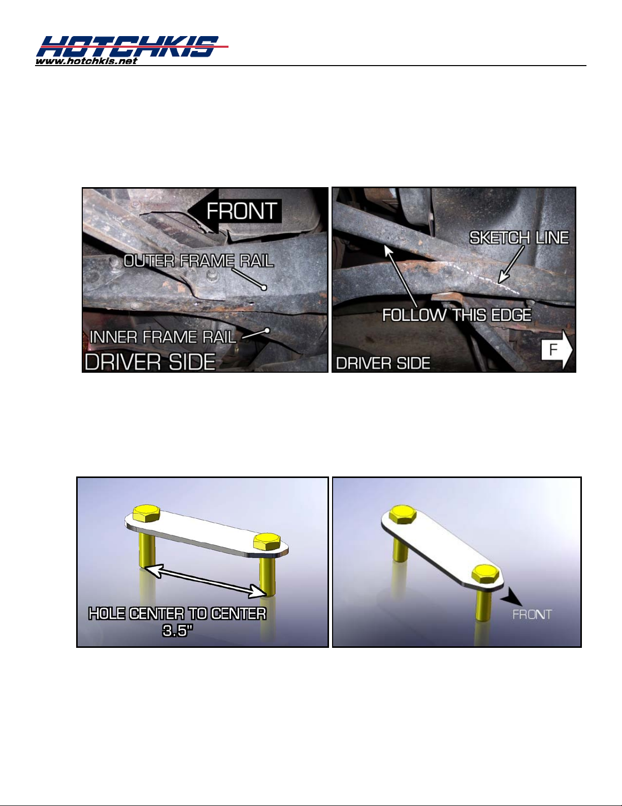
Drill Holes for the Bushing Brackets
When looking at the front section of the chassis frame, there are 2 frame rails on each side
that extend to the front bumper. The outer frame rail is the main support for the front
bumper. The bushing brackets will be installed on the main outer frame rail, just behind
where the 2 frame rails meet. This will require you to drill 2 holes per side. Use a silver
marker to sketch out a line, depicting where the inner frame rail joins the outer rail.
Your Hotchkis kit includes bushing bracket reinforcement plates, which will be installed on the
inside of the frame rail. When measuring out where to drill the holes, your main goal is to
position the holes as far forward without contacting the inner frame rails. See picture for
more details. Make sure the 2 holes are parallel with the length of the car. Drill the holes
using a 7/16” drill bit. Remember to always wear safety glasses when drilling.
Page 3

Page 4
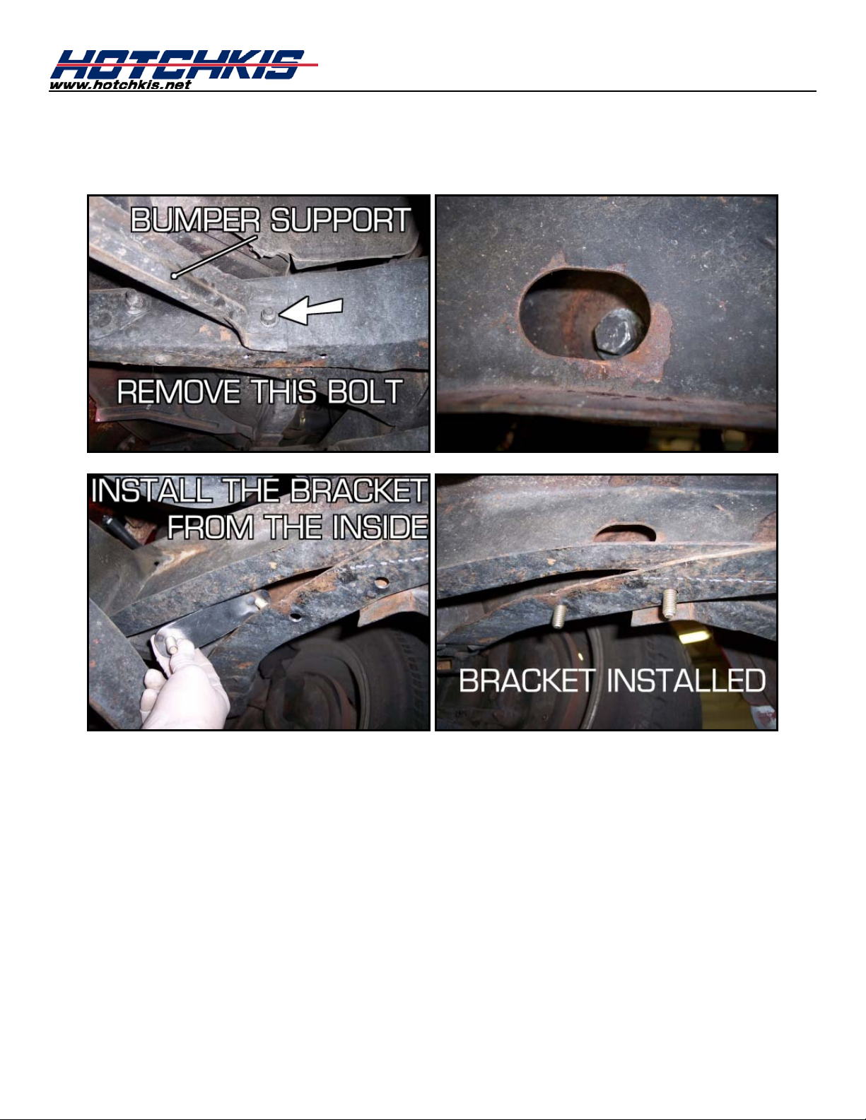
Once the holes are drilled out, undo the nut & bolt that holds the bumper support to the frame
rail. This will give you enough clearance to install the reinforcement plate inside the frame
rail. Install both reinforcement pl ates and re-install the bumper support nut & bolt.
Page 5
3F
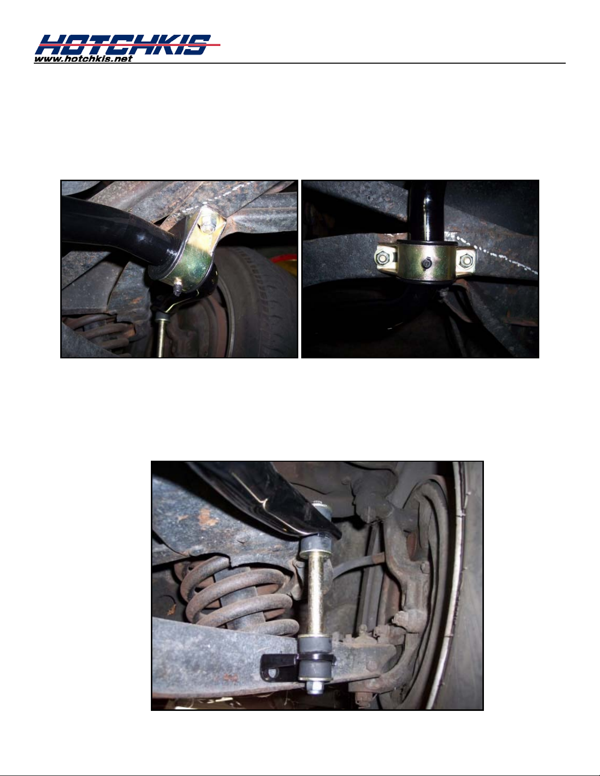
Install the Bushing Brackets
With the holes drilled out and reinforcement plates in position, yo u are now r eady to install the
bushing brackets. Apply the supplied silicon grease on the inside of each bushing. Install the
bushings onto the sway bar. Place the bushing bracket onto the bushing. Hold the bar up to
the chassis and slide the reinforcement plate studs into the bushing bracket holes. Install the
supplied nuts to the studs. You may full y tighten these nuts.
4F
Drill Holes for the End Link Brackets
Install the end links as shown in the picture. Position the sway bar so that the end link
bracket is located on th e lower control arm properly. Important note: Mak e sure the sway
bar is centered with the car. A good way to measure this is to look at the gap between the
sway bar ends and the frame on each side.
Page 6

Mark the hole centers on the lower control arm with a marker. Once the holes are marked,
you can disassemble the end links from the bar.
Drill the holes using a 3/8” drill bit. Remember to always wear safety glasses when drilling.
Install the end link bracket onto the lower control arm with the supplied bolts.
Page 7

Reassemble the end links. Tighten the end links until you start to see the bushings begin to
bulge.
5F
Make sure to double-check all fasteners. You are now finished with the front sway bar
Double-Check for Tightness
installation.
6F
Sway Bar Stiffness
This bar has a stiffness rate of approx. 800 lbs/in.
Page 8

Installation of Hotchkis Rear Sway Bar
1R
2R
Raising Car
Raise rear of the vehicle by using a 4 post lift or drive-on ramps. Securely block the front
wheels of the vehicle. Do not remove the rear wheels during installation for safety. It is
imperative that the vehicle is at ride height for this installation.
Install U-Bolts (kit#T1722) on Rear Axle
Take the washers and nuts off of the U-bolts and slide them on top of the axle tubes on each
side. They should be centered and approx. 27” apart from each other. If you have any brake
lines in the way, you must relocate them. This could be as easy as unclipping them and
bending them away from the axle tubes. Apply the supplied anti-seize to the threads of the Ubolts.
Page 9

3R
Next, we are going to put all of the components on the sway bar before we install it on the
Prepare the Rear Sway Bar
car. Grease the inside surface of the bushings with the supplied silicon lube. Install them on
the sway bar along with the bushing brackets.
You will also need to grease the outside surface of the dogbone end link bushings. Install the
end link onto the sway bar ends as shown in the picture. Use the hole closest to the end for
installation purposes. Next, install the frame bracket onto the other end of the end link. The
bolts do not need to be fully tight a t t hi s time, but they should be snug.
Page 10

End Link Hardware Order:
½” Bolt - Lg.Washer - Dog Bone End Link - Sway bar - Sm.Washer -Nut
4R
Now we are going to bring the assemble sway bar to the rear axle. Also grab the axle
Mount the Sway Bar onto the Rear Axle
brackets at the same time. These will have to go on between the axle and the bushing
bracket. See picture for more details. When tightening the u-bolt nuts, make sure the u-bolt
is pointing straight down. I.e. The u-bolt should not be at an angle with the ground.
Page 11

5R
Drill Holes for the Frame Brackets
You’re going to be drilling 2 holes for the frame brackets on each side. But first we need to
know where to drill the holes. Rotate the sway bar up to it’s normal position. Make sure the
sway bar is centered with the car. Next, position the end link so that it is slightly tilting
towards the back of the car. The reason for tilting it back is so you can use either sway bar
hole and the end link can stay fairly vertical in both positions. Make sure the frame bracket
has it’s flat side facing the frame. Mark the hole centers with a silver pen. Push the end links
out of the way and drill out the 2 holes with a 7/16” bit. Remember to always wear safety
glasses when drilling.
Page 12

6R
Carefully insert the shorty U-bolt into one of your frame bracket holes you just drilled. Rotate
Install Shorty U-Bolts (kit #1718) onto Frame
the U-bolt down so that it pokes out throu gh the s econ d hole. It might be a good idea to spin
on a nut temporarily on one end when doing this.
Page 13

7R
Now that you have the shorty U-bolts are in place you can bolt up the frame bracket to the
Bolt the Frame Brackets to the Fra me
frame. To make things easier, unbolt the frame bracket from the end link before you fasten
the bracket to the frame. This will allow you to get to nuts easier.
Page 14

8R
Double Check Hardw a re
Make sure all hardware is fully tightened before driving the vehicle. You are done with the
installation. The vehicle does not r eq ui r e an alignment after this installatio n.
9R
Stiffness Adjustment
Your Hotchkis rear bar has 2 adjustment holes, which allows you to change the sway bar
stiffness harder or softer. The hole closets to the sway bar end is the softer setting, while the
hole furthest from the end is the stiffest. The stiffness values are as follows:
Soft Setting: 310 lbs/in added
Stiff Setting: 385 lbs/in ad ded
Page 15

Hotchkis Performance LLC
Return Policy & Limited Warra nty
Effective December 1, 2010 all Hotchkis products must be registered to qualify for warranty at
www.hotchkis.net or via t he mail-in warranty card, included with the product, within 30 days of the
original purchase date.
IMPORTANT: This warranty supersedes all other warranties included with this product.
Return Policy
We want you to be completely satisfied with your Hotchkis Performance product. For products, presenting signs of
shipping damage please contact the freight carrier immediately. All our products are guaranteed to be free from
manufacturer’s def ec ts . If your or der arr ives wit h a manufacture def ec t, pl ease contact our Cust omer Service Department
at (562) 907-7757. You will be ass igned a R eturned Goods Authorizat ion Num ber (RGA). The pack age you return m ust
show the RGA on the out side of the package, include the original invoic e and be shipped prepaid to our facility. The
product has to be unused and in its original packaging materials. Exchanges or refunds made after 30 days will be
subject to a 20% restocking charge. If you purchased your Hotchkis Performance product from an authorized
dealer, you are still covered by this return policy. All returns however, should be made to your dealer, not to
Hotchkis Performance directly.
Limited Warranty
Hotchkis Performance offers a Limited Warranty against defects in materials and workmanship for the term of 36 months
(3 years) from the date of purchase of this product. This Warranty only applies to the original retail purchaser who retains
ownership of the vehicle on which the product was originally installed. If the product is determined to be defective,
Hotchkis Performance will repair, replace or refund the purchase price of the defective product at Hotchkis Performance's
sole discretion, which shall fully satisfy and discharge any and all warranty claims. Any repaired or replaced product will
be returned to the sender excluding the cost of freight.
www.hotchkis.net or via the mail-in warranty card, included with the product, within 30 days of the original
purchase date.
Products must be registered to qualify for warranty at
Exclusions from Warranty
Items offered but not manuf actured by Hotchkis Performanc e are warranted according to the manufac turer's terms and
are not covered by this limited warranty. Hotchkis Performance shall not be responsible for any labor, removal,
installation, re-installation or maintenance costs. This warranty does not cover the cosmetic finish or plating of any
product or any normal wea r and tear to any product inc luding, but not limited to b ushings, bracket s, end-links, hardware,
steering components, shocks or springs. In addition, this warranty does not apply to any products that have been:
Improperly installed or installed by someone other than a qualified, licensed aut o mechanic experienced in the
installation and removal of suspension products;
Improperly serviced, misused, or modified, altered or subjected to abuse, negligence, accident or collision; Installed in any vehicle that has been modified; Installed on any vehicle that has carried loads in excess of automobile manufacturer suggested weight limits; or Installed on any vehicle that has been subject to abnormal or excessive use, including rallying, racing, or racing-type
activities or off-road use.
Limitation of Warranty
This limited warranty is the entire and only warranty for the products and may not be modified or supplem ented by any
other person or company in any form . Any description of the produc ts, by anyone, is for the sole purpos e of identifying
them and is not part of the basis of the barga in, and d oes not constitute a war ranty that th e products wil l conform to that
description. The statem ents of any salesperso n do not constitute part of this limited warranty and cannot be relied upon
as a warranty.
THERE ARE NO WARRANTIES, EXPRESSED OR IMPLIED, INCLUDING ANY IMPLIED WARRANTIES OF
MERCHANTABILITY OR FITNESS FOR A PARTICULAR PURPOSE, WHICH EXTEND BEYOND THE
DESCRIPTION ON THE FACE HEREOF. ANY IMPLIED WARRANTIES ARE DISCLAIMED TO THE
FULLEST EXTENT PERMITTED BY LAW. THIS WARRANTY DOES NOT COVER CONSEQUENTIAL
DAMAGES, LOSS OF TIME OR REVENUES, INCONVENIENCE, LOSS OF USE OF THE VEHICLE,
 Loading...